EP0793208B1 - Sicherheitsvorrichtung für eine Walzen-Knetmaschine - Google Patents
Sicherheitsvorrichtung für eine Walzen-Knetmaschine Download PDFInfo
- Publication number
- EP0793208B1 EP0793208B1 EP97103141A EP97103141A EP0793208B1 EP 0793208 B1 EP0793208 B1 EP 0793208B1 EP 97103141 A EP97103141 A EP 97103141A EP 97103141 A EP97103141 A EP 97103141A EP 0793208 B1 EP0793208 B1 EP 0793208B1
- Authority
- EP
- European Patent Office
- Prior art keywords
- light
- rolls
- kneading machine
- reflection member
- worker
- Prior art date
- Legal status (The legal status is an assumption and is not a legal conclusion. Google has not performed a legal analysis and makes no representation as to the accuracy of the status listed.)
- Expired - Lifetime
Links
- 238000004898 kneading Methods 0.000 title claims description 121
- 238000012360 testing method Methods 0.000 claims description 66
- 238000001514 detection method Methods 0.000 claims description 56
- 239000000463 material Substances 0.000 claims description 52
- 210000000707 wrist Anatomy 0.000 claims description 37
- 230000010287 polarization Effects 0.000 claims description 26
- 230000002093 peripheral effect Effects 0.000 claims description 10
- 230000008859 change Effects 0.000 claims description 6
- 230000001678 irradiating effect Effects 0.000 claims description 2
- 231100001261 hazardous Toxicity 0.000 description 15
- 238000005192 partition Methods 0.000 description 14
- 238000010586 diagram Methods 0.000 description 12
- 230000000052 comparative effect Effects 0.000 description 8
- 238000010438 heat treatment Methods 0.000 description 5
- 238000000034 method Methods 0.000 description 5
- 230000003287 optical effect Effects 0.000 description 5
- 230000004044 response Effects 0.000 description 5
- 210000004247 hand Anatomy 0.000 description 4
- 238000001228 spectrum Methods 0.000 description 4
- 230000005856 abnormality Effects 0.000 description 3
- 230000005540 biological transmission Effects 0.000 description 3
- 230000002159 abnormal effect Effects 0.000 description 2
- 239000003990 capacitor Substances 0.000 description 2
- 239000004020 conductor Substances 0.000 description 2
- 230000012447 hatching Effects 0.000 description 2
- NJPPVKZQTLUDBO-UHFFFAOYSA-N novaluron Chemical compound C1=C(Cl)C(OC(F)(F)C(OC(F)(F)F)F)=CC=C1NC(=O)NC(=O)C1=C(F)C=CC=C1F NJPPVKZQTLUDBO-UHFFFAOYSA-N 0.000 description 2
- 230000005855 radiation Effects 0.000 description 2
- 238000007493 shaping process Methods 0.000 description 2
- 235000016936 Dendrocalamus strictus Nutrition 0.000 description 1
- 206010016275 Fear Diseases 0.000 description 1
- 229910000831 Steel Inorganic materials 0.000 description 1
- 239000003795 chemical substances by application Substances 0.000 description 1
- 230000005684 electric field Effects 0.000 description 1
- 238000005286 illumination Methods 0.000 description 1
- 230000002401 inhibitory effect Effects 0.000 description 1
- 238000007689 inspection Methods 0.000 description 1
- 230000004048 modification Effects 0.000 description 1
- 238000012986 modification Methods 0.000 description 1
- 230000008569 process Effects 0.000 description 1
- 239000002994 raw material Substances 0.000 description 1
- 239000012779 reinforcing material Substances 0.000 description 1
- 239000010959 steel Substances 0.000 description 1
Images


Classifications
-
- F—MECHANICAL ENGINEERING; LIGHTING; HEATING; WEAPONS; BLASTING
- F16—ENGINEERING ELEMENTS AND UNITS; GENERAL MEASURES FOR PRODUCING AND MAINTAINING EFFECTIVE FUNCTIONING OF MACHINES OR INSTALLATIONS; THERMAL INSULATION IN GENERAL
- F16P—SAFETY DEVICES IN GENERAL; SAFETY DEVICES FOR PRESSES
- F16P3/00—Safety devices acting in conjunction with the control or operation of a machine; Control arrangements requiring the simultaneous use of two or more parts of the body
- F16P3/12—Safety devices acting in conjunction with the control or operation of a machine; Control arrangements requiring the simultaneous use of two or more parts of the body with means, e.g. feelers, which in case of the presence of a body part of a person in or near the danger zone influence the control or operation of the machine
- F16P3/14—Safety devices acting in conjunction with the control or operation of a machine; Control arrangements requiring the simultaneous use of two or more parts of the body with means, e.g. feelers, which in case of the presence of a body part of a person in or near the danger zone influence the control or operation of the machine the means being photocells or other devices sensitive without mechanical contact
- F16P3/148—Safety devices acting in conjunction with the control or operation of a machine; Control arrangements requiring the simultaneous use of two or more parts of the body with means, e.g. feelers, which in case of the presence of a body part of a person in or near the danger zone influence the control or operation of the machine the means being photocells or other devices sensitive without mechanical contact using capacitive technology
-
- F—MECHANICAL ENGINEERING; LIGHTING; HEATING; WEAPONS; BLASTING
- F16—ENGINEERING ELEMENTS AND UNITS; GENERAL MEASURES FOR PRODUCING AND MAINTAINING EFFECTIVE FUNCTIONING OF MACHINES OR INSTALLATIONS; THERMAL INSULATION IN GENERAL
- F16P—SAFETY DEVICES IN GENERAL; SAFETY DEVICES FOR PRESSES
- F16P3/00—Safety devices acting in conjunction with the control or operation of a machine; Control arrangements requiring the simultaneous use of two or more parts of the body
- F16P3/12—Safety devices acting in conjunction with the control or operation of a machine; Control arrangements requiring the simultaneous use of two or more parts of the body with means, e.g. feelers, which in case of the presence of a body part of a person in or near the danger zone influence the control or operation of the machine
- F16P3/14—Safety devices acting in conjunction with the control or operation of a machine; Control arrangements requiring the simultaneous use of two or more parts of the body with means, e.g. feelers, which in case of the presence of a body part of a person in or near the danger zone influence the control or operation of the machine the means being photocells or other devices sensitive without mechanical contact
- F16P3/144—Safety devices acting in conjunction with the control or operation of a machine; Control arrangements requiring the simultaneous use of two or more parts of the body with means, e.g. feelers, which in case of the presence of a body part of a person in or near the danger zone influence the control or operation of the machine the means being photocells or other devices sensitive without mechanical contact using light grids
-
- F—MECHANICAL ENGINEERING; LIGHTING; HEATING; WEAPONS; BLASTING
- F16—ENGINEERING ELEMENTS AND UNITS; GENERAL MEASURES FOR PRODUCING AND MAINTAINING EFFECTIVE FUNCTIONING OF MACHINES OR INSTALLATIONS; THERMAL INSULATION IN GENERAL
- F16P—SAFETY DEVICES IN GENERAL; SAFETY DEVICES FOR PRESSES
- F16P3/00—Safety devices acting in conjunction with the control or operation of a machine; Control arrangements requiring the simultaneous use of two or more parts of the body
- F16P3/12—Safety devices acting in conjunction with the control or operation of a machine; Control arrangements requiring the simultaneous use of two or more parts of the body with means, e.g. feelers, which in case of the presence of a body part of a person in or near the danger zone influence the control or operation of the machine
- F16P3/14—Safety devices acting in conjunction with the control or operation of a machine; Control arrangements requiring the simultaneous use of two or more parts of the body with means, e.g. feelers, which in case of the presence of a body part of a person in or near the danger zone influence the control or operation of the machine the means being photocells or other devices sensitive without mechanical contact
- F16P3/147—Safety devices acting in conjunction with the control or operation of a machine; Control arrangements requiring the simultaneous use of two or more parts of the body with means, e.g. feelers, which in case of the presence of a body part of a person in or near the danger zone influence the control or operation of the machine the means being photocells or other devices sensitive without mechanical contact using electro-magnetic technology, e.g. tags or radar
Definitions
- the detection reflection member attached to the hand of the worker receives light from the light projector and reflects only light of the specific property
- the photoelectric sensors receive the light
- the emergency stopping means stops the operation of the kneading machine.
- the invention provides a safety device for a kneading machine having configuration 6 ⁇ in which the light projector of configuration 3 ⁇ or 4 ⁇ or the light projector and the test light projector of configuration 5 ⁇ emit only substantially linearly polarized light, the detection reflection member and the test reflection member of configuration 8 ⁇ or the detection reflection member of configuration 4 ⁇ or 5 ⁇ reflects incident light with changing polarization direction of the light, and the photoelectric sensors of configuration 3 ⁇ or 4 ⁇ or the photoelectric sensors and the test photoelectric sensor of configuration 8 ⁇ receive only substantially linearly polarized light having a polarization direction obtained in the case where light from the light projector or the test light projector is reflected by the detection reflection member or the test reflection member.
- the safety device can detect a hand of the worker or the like which enters the hazardous region in the vicinity of the gap between the rolls with surely distinguishing it from the rubber material or the roll.
- an electrostatic capacitance sensor 1 is used as the sensor.
- a rod-like bar electrode 2 is attached to the electrostatic capacitance sensor 1.
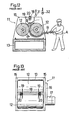
- the bar electrode 2 elongates so that its longitudinal direction coincides with the axial direction of the rolls 12 of the kneading machine 11, and is located at a position which is above the rolls 12 and below the partition moving bar 18 shown in Fig. 12.
- the bar electrode 2 is bent into an adequate shape so as not to obstruct the work of kneading the rubber material B, thereby ensuring the main space above the gap between the rolls 12.
- the electrostatic capacitance detected by the electrostatic capacitance sesnor 11 has a substantially constant value.
- the sensor detects the synthesized capacitance of the series circuit of the electrostatic capacitance of the portion where air exists and that of the portion where the rubber material B exists. Therefore, the detected electrostatic capacitance is increased in accordance with the quantity and the shape of the rubber material B.
- the safety device may be configured so that, during a period when, for example, a switch positioned at the base of the kneading machine 11 is operated, the driving unit 11a is inhibited from stopping the operation even when the control signal instructing the operation to be stopped is sent from the judging circuit 3.
- the worker A is requested to press the switch with a foot only when the partition plates 19 are to be adjusted, thereby preventing the machine from being unnecessarily stopped.
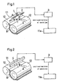
- Figs. 4 to 6 show a first embodiment of the invention.
- Fig. 4 is a block diagram of the safety device for a kneading machine
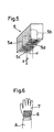
- Fig. 5 is a perspective view partially in section illustrating the structure of a photoelectric sensor
- Fig. 6 is a plan view showing a reflection member sewn on a glove.
- the members having the same functions as those of the prior art example shown in Figs. 12 and 13 and the first embodiment shown in Fig. 1 are designated by the same reference numerals and their description is omitted.
- a polarizing plate 5c which allows only light linearly polarized in the X-direction to pass therethrough is disposed in front of each light projector 5a
- a polarizing plate 5d which allows only light linearly polarized in the Y-direction perpendicular to the X-direction to pass therethrough is disposed in front of each photoelectric sensor 5b.
- a detection reflection member 6 is sewn on the portion corresponding to the back of a hand as shown in Fig. 6.
- a number of minute concave reflecting faces are arranged on the surface and a quarter wave length plate is disposed on the reflecting faces. Reflecting faces return incident light to the incident direction at a high efficiency when the faces have a shape of an inverted circular cone of an apex angle of 90°. Even when reflecting faces have a curved concave shape, the reflecting faces surely return part of incident light to the incident direction.
- the reflecting faces may be configured by minute convexes or a flat face for scattering reflected light, in place of the minute concaves.
- the quarter wave length plate may be replaced with an optical device of another kind, as far as it has the same function. Alternatively, an optical device having both the functions of the reflecting faces and the quarter wave length plate may be used.
- the value of the quantity of light received by the photoelectric sensors 5b housed in the case 5 is supplied at any time to the judging circuit 3 which in turn judges whether the supplied value of the received light quantity exceeds a predetermined value or not.
- the judging circuit 3 sends a control signal in accordance with a result of the judgment to the driving unit 11a of the kneading machine 11. Specifically, when it is judged that the received light quantity light exceeds the predetermined value, a control signal instructing the operation of the kneading machine 11 to be stopped is sent to the driving unit 11a. When the received light quantity does not exceed the predetermined value, a control signal instructing the operation to be continued is sent.
- the driving unit 11a when the driving unit 11a receives the contorol signal instructing the continuation of the operation, the operation of the kneading machine 11 is continued as it is.
- the driving unit 11a receives the contorol signal instructing the stop of the operation, the rotation of the rolls 12 is immediately stopped and the operation of the kneading machine 11 is stopped.
- the judging circuit 3 sends a control signal instructing the operation of the kneading machine 11 to be stopped, to the driving unit 11a.
- the driving unit 11a immediately stops the rotation of the rolls 12. Therefore, the operation of the kneading machine 11 can be surely stopped before the hand of the worker A is caught in the rotation of the rolls 12, thereby preventing an accident from occurring.
- the photoelectric sensors 5b may be configured by light receiving devices for receiving only light of a color such as yellow or green which is little included in the wavelength components of light reflected from the rolls 12 or the rubber material B, and the detection reflection member 6 may be formed by a reflection tape or the like which reflects only light of the same color such as yellow or green or the glove 7 itself may be configured as the reflection member 6 and have a color such as yellow or green. Also in this case, light reflected from the rolls 12 or the rubber material B can be distinguished from that from the detection reflection member 6.
- the photoelectric sensors 5b may be sensitive only to light of a specific wavelength range, or a filter which allows only light of a specific wavelength range to pass therethrough may be disposed in front of usual light receiving devices.
- the judging circuit 3 sends a control signal instructing the operation to be stopped, on the basis of the physical quantity detected by the electrostatic capacitance sensor 1, the heat ray sensor 4, or the photoelectric sensors 5b.
- a sensor may be used in combination with another sensor which is disposed at another position, and the judging circuit 3 may send a control signal instructing the operation to be stopped, only when the detection results of the sensors satisfy predetermined conditions.
- the photoelectric sensors 5b when the photoelectric sensors 5b receive light of a specific polarization direction or a specific color, the photoelectric sensors 5b causes the safety device to operate. Even when a situation occurs in which the photoelectric sensors 5b cannot receive light because of a fault, therefore, it is impossible to distinguish this situation from the normal situation in which the photoelectric sensors do not receive light. In other words, in a safety device of a type in which abnormality is detected on the basis of reception of light in the photoelectric sensors 5b, the device cannot be configured so as to have a fail-safe structure in which, when a fault causes a photoelectric sensor which currently receives light to conduct the output in the same manner as the case where the sensor does not receive light, or when a fault occurs, the device operates in a safer manner.
- second and third embodiments can solve this problem as described below.
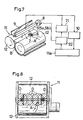
- Figs. 7 and 8 show the second embodiment of the invention.
- Fig. 7 is a block diagram of a safety device for a kneading machine
- Fig. 8 is a plan view of the kneading machine showing the directional pattern of photoelectric sensors.
- photoelectric sensors are used for detecting the entry of a hand of the worker into the hazardous region on the basis of polarization of light.
- the polarizing plate 5c which allows only light linearly polarized in the X-direction to pass therethrough is disposed in front of each light projector 5a
- the polarizing plate 5d which allows only light linearly polarized in the Y-direction perpendicular to the X-direction to pass therethrough is disposed in front of each photoelectric sensor 5b.
- the polarizing plates 5c and 5d may be configured by polarizers of another kind, as far as the polarizers function in the same manner.
- the case 5 which houses the light projectors 5a and the photoelectric sensors 5b are attached to a rotary solenoid 8 so that the case can be rotated by 90° about the rotation shaft which is parallel to the rolls 12.
- a test reflection member 9 which has a long plate-like shape and elongates substantially along the case 5 is disposed on the side to which the case 5 can be oriented by rotation.
- the side which opposes the case is formed as a mirror reflecting face and a quarter wave length plate is disposed in front of the reflecting face.
- the safety device of the embodiment is configured so that the worker A conducts the work while wearing the gloves 7 in each of which the detection reflection member 6 is sewn on the portion corresponding to the back of a hand as shown in Fig. 6.
- signals of the received light quantity output from the photoelectric sensors 5b are supplied at any time to an emergency stopping circuit 10.
- the emergency stopping circuit 10 supplies the operation stop signal to the driving unit 11a of the kneading machine 11.
- the driving unit 11a receives the operation stop signal from the emergency stopping circuit 10
- the rotation of the rolls 12 is immediately stopped and the operation of the kneading machine 11 is stopped.
- the signals of the received light quantity output from the photoelectric sensors 5b are supplied at any time also to a test circuit 21.
- the driving unit 11a supplies a roll stop signal to a light receive object switching circuit 22.
- the light receive object switching circuit 22 drives the rotary solenoid 8 so as to rotate the case 5 housing the light projectors 5a and the photoelectric sensors 5b by 90°, and supplies an operation enable signal to the test circuit 21, only during a period when the light receive object switching circuit receives the roll stop signal.
- the test circuit 21 checks the received light quantity supplied from the photoelectric sensors 5b to judge whether the quantity exceeds a predetermined value or not, only during a period when the circuit receives the operation enable signal. If the received light quantity from even one of the photoelectric sensors 5b fails to exceed the predetermined value, the test circuit sends out a warning.
- the warning may be realized by any means as far as the worker A, etc. can know a fault of the photoelectric sensors 5b. Usually, the warning is realized by means of lighting of a lamp or a sound of a buzzer. Alternatively, lamps which normally emit green light may be allocated to the photoelectric sensors 5b, and, when the test circuit 21 detects a fault, the lamp corresponding to the faulty photoelectric sensor 5b may be switched so as to emit red light.
- the test circuit 21 supplies an operation stop signal which is not shown to the driving unit 11a at the same time with the issuance of the warning, thereby inhibiting the rotation of the rolls 12 even when the worker A instructs the machine to operate.
- the emergency stopping circuit 10 sends a control signal instructing the operation to be stopped, to the driving unit 11a.
- the driving unit 11a immediately stops the rotation of the rolls 12. Therefore, the operation of the kneading machine 11 can be surely stopped before the hand of the worker A is caught in the rotation of the rolls 12, thereby preventing an accident from occurring.
- the rotation of the rolls 12 is stopped. Even when a hand of the worker A enters the hazardous region in the vicinity of the gap between the rolls 12 during this period, there arises no particular hazardous situation.
- the light receive object switching circuit 22 drives the rotary solenoid 8 so as to rotate the case 5 housing the light projectors 5a and the photoelectric sensors 5b by 90°, and the test circuit 21 starts the check of the received light quantity signals supplied from the photoelectric sensors 5b to judge whether the quantities exceed the predetermined value or not.
- the test circuit 21 detects that the quantity of light received by the photoelectric sensor 5b exceeds the predetermined value. In the case where even one of the photoelectric sensors 5b is faulty or a detection circuit for one of the photoelectric sensors 5b is abnormal, the test circuit 21 detects that the quantity of light received by the photoelectric sensor 5b fails to exceed the predetermined value, and sends out a warning.
- the worker A can know a fault of the photoelectric sensors 5b or the like from this warning and hence there arises no danger that the worker A starts the work without knowing the faulty state of the safety device and an accident is caused.
- the photoelectric sensors 5b are checked before the start of the work or when the worker A stops the operation. It is not necessary to conduct the check in all periods when the rotation of the rolls 12 is stopped. The check may be conducted only before the start of the work.
- the case 5 is rotated by the rotary solenoid 8.
- the case may be rotated by another driving device or manually rotated.
- the light projectors 5a and the photoelectric sensors 5b are oriented toward the test reflection member 9 by rotating the case 5.
- the optical paths of the light projectors 5a and the photoelectric sensors 5b may be guided to the test reflection member 9 by using mirrors and the like, or the test reflection member 9 itself may be moved so as to be positioned between the light projector 5a and the photoelectric sensors 5b, and the rolls 12.
- plural pairs of the light projector 5a and the photoelectric sensor 5b are disposed.
- one or more light projectors 5a may be disposed independently from the photoelectric sensors 5b.
- Figs. 9 and 10 show a third embodiment of the invention.
- Fig. 9 is a block diagram of a safety device for a kneading machine
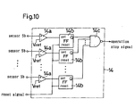
- Fig. 10 is a block diagram showing the configuration of an operation start restricting circuit.
- the members having the same functions as those of the fourth embodiment shown in Figs. 7 and 8 are designated by the same reference numerals and their description is omitted.
- the safety device for a kneading machine of the embodiment is configured in a substantially same manner as the second embodiment.
- the test reflection member 9 and the rotary solenoid 8 which are used in the second embodiment are not disposed, and the light receive object switching circuit 22 is not used. Therefore, the case 5 is not rotated, and the light projectors 5a and the photoelectric sensors 5b are always oriented to the hazardous region in the vicinity of the gap between the rolls 12.
- an operation start restricting circuit 14 which supplies the operation stop signal the driving unit 11a is disposed.
- the operation start restricting circuit 14 receives signals indicative of the received light quantity and output from the photoelectric sensors 5b. In the initial state after the power of the machine is turned on, the circuit always supplies the operation stop signal to the driving unit 11a. After the received light quantities of all the photoelectric sensors 5b once exceed a predetermined value, the circuit ceases the supply of the operation stop signal to the driving unit 11a.
- Fig. 10 shows an example of the configuration of the operation start restricting circuit 14 which operates as described above.
- the signals of the received light quantity from the photoelectric sensors 5b are supplied to set terminals of RS flip-flop circuits 14b through comparators 14a, respectively.
- the comparators 14a are binarizing circuits for outputting a signal which has H level when the voltage of the signal indicative of the received light quantity of the corresponding the photoelectric sensor 5b exceeds a predetermined reference voltage Vref.
- a reset signal which has H level only one time after the power of the machine is turned on is supplied to the reset terminals of the RS flip-flop circuits 14b.
- the outputs Q of the RS flip-flop circuits 14b are supplied to a NAND circuit 14c.
- a lamp may be provided for each of the RS flip-flop circuits 14b. When the corresponding flip-flop circuit 14b is reset, the lamp may be controlled so as to emit red light, and, when the circuit is set, switched so as to emit green light.
- the operation start restricting circuit 14 immediately after the power of the kneading machine 11 is turned on, the operation start restricting circuit 14 continues to supply the operation stop signal to the driving unit 11a. Even when the worker A instructs the machine to operate, therefore, the operation cannot be started.
- the worker A conducts a checking work in which a hand bearing the glove 7 is held below the case 5 housing the light projectors 5a and the photoelectric sensors 5b and then moved along the case 5, the photoelectric sensors 5b sequentially receive light linearly polarized in the Y-direction and emitted from the detection reflection member 6.
- the operation start restricting circuit 14 ceases the output of the operation stop signal.
- the operation of the kneading machine 11 can be started in response to the operation instructions given by the worker A.
- the operation start restricting circuit 14 is provided with the lamps, immediately after the power of the kneading machine 11 is turned on, all the lamps emit red light, and, when the worker A holds a hand below the photoelectric sensors 5b, the lamps corresponding to the photoelectric sensors 5b are sequentially switched to emit green light. When all the lamps emit green light, the worker can know that the operation is enabled.
- the checking work by the worker A is executed in, for example, start-up inspection to be conducted every morning.
- the received light quantity fails to exceed the predetermined value even when the worker A holds a hand below the photoelectric sensor 5b, and the operation start restricting circuit 14 continues to output the operation stop signal.
- the operation start restricting circuit 14 is provided with the. lamps, only the lamp corresponding to the faulty photoelectric sensor 5b remains to emit red light. Consequently, there arises no danger that the worker A starts the work without knowing the faulty state of the safety device and an accident is caused.
- the photoelectric sensors 5b are checked by using the detection reflection member 6 of the glove 7 which is actually attached to a hand of the worker A.
- the photoelectric sensors 5b are checked only before the kneading work is started.
- the checking work may be conducted at any time during a period when the rotation of the rolls 12 is stopped.
- light reflected from the rolls 12 or the rubber material B is distinguished from that from the reflection member 6 attached to a hand of the worker A, on the basis of polarization of light.
- the photoelectric sensors 5b may be configured by light receiving devices for receiving only light of a color such as yellow or green which is little included in the wavelength components of light reflected from the rolls 12 or the rubber material B.
- test reflection member 9 and the detection reflection member 6 used in the second embodiment, and the detection reflection member 6 used in the third embodiment may be formed by a reflection tape or the like which reflects only light of the same color such as yellow or green.
- Light receiving devices which are sensitive only to light of a specific wavelength range may be used as the photoelectric sensors 5b, or a filter which allows only light of a specific wavelength range to pass therethrough may be disposed in front of usual light receiving devices.
- the reflection member 6 is sewn on the glove 7.
- the glove 7 itself may be formed by the reflection member 6, the reflection member 6 may be formed into a wrist band-like shape so as to be directly attached to a wrist, or the reflection member 6 may be attached to a hand, a finger, a wrist, or the front portion of an arm of the worker A by an arbitrary method.
- the detection reflection member 6 is formed on the whole of the outer peripheral face of a wrist band and then attached to a wrist of the worker A. Even in the case only a part of the whole periphery of the detection reflection member 6 becomes dirty and cannot reflect light, when the worker A holds a hand with orienting the face of the detection reflection member 6 which is not dirty toward the photoelectric sensors 5b, the operation start restricting circuit 14 ceases the output of the operation stop signal, thereby producing a danger that the operation of the kneading machine 11 can be started.
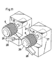
- the safety device may be provided with a checking device which checks dirtiness or the like of the detection reflection member 6 disposed on a wrist band 25.
- the checking device comprises a pair of cylindrical supporting members 26.
- the wrist bans 25 are fitted onto the outer peripheries of the supporting members, respectively.
- the supporting members 26 are rotated by small motors 27.
- Test photoelectric detectors 28 are disposed below the supporting members 26, respectively.
- Each of the test photoelectric detectors consists of a set of the light projector 5a, the polarizing plate 5c, the photoelectric sensor 5b, and the polarizing plate 5d which are the same as those described above.
- Each test photoelectric detector 28 is configured so that the test light projector in the detector irradiates the detection reflection member 6 attached to the supporting member 26 on the opposite side, with light linearly polarized in the X-direction, and the test photoelectric sensor in the test photoelectric detector 28 receives only light linearly polarized in the Y-direction from a partial region of the detection reflection member 6.
- a control circuit which is not shown allows the small motors 27 to make one or more turns at a timing such as that when the power of the kneading machine 11 is turned on.
- the control circuit controls the operation start restricting circuit 14 so as not to cease the output of the operation stop signal.
- the worker A is requested to previously attach a pair of wrist bands 25 to the supporting members 26, so that the detection reflection members 6 of the wrist bands 25 can be checked at the same time when the power is turned on.
- the detection reflection members 6 of the wrist bands 25 can be checked at the same time when the power is turned on.
- a period when the received light quantity of the test photoelectric sensor in the corresponding test photoelectric detector 28 does not exceed the predetermined value is produced, and the operation start restricting circuit 14 is thereafter controlled so as not to cease the output of the operation stop signal. Therefore, it is possible to prevent a danger that the worker A uses a dirty detection reflection member 6 and the safety device does not operate, from occurring.
- the worker A detaches the wrist bands 25 from the supporting members 26 and wears the bands on the writs. Thereafter, the worker A holds either of the wrist bands, so that the output of the operation stop signal from the operation start restricting circuit 14 is ceased, with the result that the operation of the kneading machine 11 can be started.
- the safety device for a kneading machine of the invention a danger such as that a hand of the worker is caught in the rotation of rolls is previously detected and the operation of the kneading machine is stopped. Therefore, the invention can provide a working environment in which a serious accident is prevented from occurring and high safety is attained. Particularly, abnormality such as a fault of a photoelectric sensor can be detected automatically or in response to an operation of the worker before the start of the work or each time when the rotation of the rolls is stopped. Therefore, it is possible to prevent a situation that the worker starts the work without knowing a fault or a dirty state of the detection reflection member and an accident is caused, from arising.
Landscapes
- Engineering & Computer Science (AREA)
- General Engineering & Computer Science (AREA)
- Mechanical Engineering (AREA)
- Radar, Positioning & Navigation (AREA)
- Remote Sensing (AREA)
- Processing And Handling Of Plastics And Other Materials For Molding In General (AREA)
- Mixers With Rotating Receptacles And Mixers With Vibration Mechanisms (AREA)
Claims (6)
- Sicherheitseinrichtung für eine Knetmaschine (11), in der zwei seitlich nebeneinanderliegende Walzen (12) so angeordnet sind, dass die peripheren Seitenflächen der Walzen (12) dicht aneinander liegen und so gedreht werden, dass die Bewegungen von beiden der sich gegenüberliegenden peripheren Seitenflächen der Walzen (12) nach unten gerichtet sind, wodurch ein Gummimaterial geknetet wird, wobei
ein Sensor (5b) zum Detektieren einer physikalischen Menge, die durch Eintritt einer Hand einer Arbeitsperson in einem Bereich in der Nähe einer Lücke zwischen den Walzen (12) verändert wird, angeordnet ist, und die Einrichtung weiter umfasst:dadurch gekennzeichnet, dass der Sensor (5b) ein photoelektrischer Sensor vom Reflexionstyp zum Bestrahlen des Bereichs in der Nähe der Lücke zwischen den beiden Walzen (12) mit im wesentlichen nur linear polarisiertem Licht und zum Empfangen von im wesentlichen nur linear polarisiertem Licht aus diesem Bereich ist, wobei das im wesentlichen linear polarisierte Licht sich in der Polarisationsrichtung von dem Bestrahlungslicht unterscheidet, undBeurteilungsmittel (3) zum Beurteilen, ob eine Änderung der durch den Sensor (5b) detektierten physikalischen Menge einen vorbestimmten Bereich überschreitet oder nicht; undBetriebsanhaltemittel (11a) zum Anhalten des Betriebs der Knetmaschine, wenn die Beurteilungsmittel feststellen, dass die Änderung den vorbestimmten Bereich überschreitet,
wobei die Einrichtung weiter ein Reflexionselement (6) umfasst, das an einer Hand (7) oder dergleichen einer Arbeitsperson der Knetmaschine (11) zu befestigen ist und das einfallendes Licht reflektiert, wobei die Polarisationsrichtung des Lichts verändert wird. - Sicherheitseinrichtung für eine Knetmaschine (11) nach Anspruch 1, bei der der Sensor ein photoelektrischer Sensor (5b) zum Empfangen von Licht aus nur einem spezifischen Wellenlängenbereich und aus dem Bereich in der Nähe der Lücke zwischen den Walzen (12) ist, und wobei die Einrichtung weiter ein Reflexionselement (6) umfasst, das an einer Hand (7) oder dergleichen einer Arbeitsperson der Knetmaschine (11) zu befestigen ist und das nur Licht aus dem spezifischen Wellenlängenbereich reflektiert.
- Sicherheitseinrichtung für eine Knetmaschine (11) nach einem der vorherigen Ansprüche, weiter umfassend:einen Lichtprojektor (5a), der wenigstens einen Bereich in der Nähe der Lücke zwischen den beiden Walzen (12) bestrahlt;Notanhaltemittel (10) zum Anhalten des Betriebs der Knetmaschine (11), wenn wenigstens einer der photoelektrischen Sensoren Licht mit der spezifischen Eigenschaft und einer Menge empfängt, die nicht kleiner als eine vorbestimmte Menge ist;ein Testreflexionselement (9), das außerhalb der Nähe der Lücke zwischen den beiden Walzen angeordnet ist, welches Licht vom Lichtprojektor empfängt und nur Licht mit der spezifischen Eigenschaft reflektiert;eine Lichtempfangsobjektumschalteinrichtung (22), die in einer geeigneten Periode während eines Intervalls, in dem die Drehung der Walzen (12) angehalten wird, das Lichtempfangsobjekt von jedem der photoelektrischen Sensoren (5b) auf das Testreflexionselement (9) umschaltet; undTestmittel (21) zum Testen eines Lichtempfangszustands von jedem der photoelektrischen Sensoren (5b), in der Periode, in der die Lichtempfangsobjektumschalteinrichtung (22) das Lichtempfangsobjekt von jedem der photoelektrischen Sensoren (5b) auf das Testreflexionselement (9) umschaltet, und zum Aussenden einer Warnung, wenn ein photoelektrischer Sensor (5b) gefunden wird, der kein Licht mit der spezifischen Eigenschaft und mit einer Menge empfängt, die nicht kleiner als die vorbestimmte Menge ist.
- Sicherheitseinrichtung für eine Knetmaschine (11) nach einem der vorherigen Ansprüche, weiter umfassend:einen Lichtprojektor (5a), der wenigstens einen Bereich in der Nähe der Lücke zwischen den beiden Walzen (12) bestrahlt;Notanhaltemittel (10) zum Anhalten des Betriebs der Knetmaschine (11), wenn wenigstens einer der photoelektrischen Sensoren (5b) Licht mit der spezifischen Eigenschaft und einer Menge empfängt, die nicht kleiner als eine vorbestimmte Menge ist;Betriebsstartbeschränkungsmittel (14) zum Einstellen eines Zustands, in dem der Betrieb der Knetmaschine (11) nicht gestartet wird, in einer geeigneten Periode während eines Intervalls, in dem die Drehung der Walzen (12) angehalten ist, und zum Beibehalten der Beschränkung des Starts des Betriebs, bis alle photoelektrischen Sensoren (5b) wenigstens einmal Licht mit der spezifischen Eigenschaft und einer Menge empfangen, die nicht kleiner als eine vorbestimmte Menge ist.
- Sicherheitseinrichtung für eine Knetmaschine (11) nach Anspruch 4, bei der das Detektionsreflexionselement (6) auf einer gesamten äußeren peripheren Fläche eines Armbandes (25) angeordnet ist, das an einer Arbeitsperson der Knetmaschine (11) angebracht ist, Licht vom Lichtprojektor (5a) empfängt und nur Licht mit der spezifischen Eigenschaft reflektiert, und wobei die Einrichtung weiter umfasst:ein Armbanddrehstützelement (26), auf dem das Armband angebracht ist, auf welchem das Detektionsreflexionselement (6) angeordnet ist, und das das Armband (25) dreht;einen Testlichtprojektor (5a), der einen Teilbereich des Detektionsreflexionselements (6) des am Armbanddrehstützelement (26) angebrachten Armbandes (25) mit Licht bestrahlt,ein photoelektrischen Testsensor (5b), der nur Licht mit einer spezifischen Eigenschaft aus dem Bereich des Detektionsreflexionselements (6) empfängt, das durch den Testlichtprojektor beleuchtet wird; undzweite Betriebsstartbeschränkungsmittel zum Einstellen eines Zustands, in dem der Betrieb der Knetmaschine (11) nicht gestartet wird, in einer geeigneten Periode während eines Intervalls, in dem die Drehung der Walzen angehalten ist, zum Bewirken der Drehung des Armbanddrehstützelements (26), so dass es wenigstens eine Drehung ausführt; und zum Beibehalten der Beschränkung des Starts des Betriebs ohne Rücksicht auf den Zustand der Betriebsstartbeschränkungsmittel, solange nicht der photoelektrische Testsensor (5b) während der gesamten Periode, in der sich das Armbanddrehstützelement (26) dreht, fortlaufend Licht mit der spezifischen Eigenschaft und einer Menge empfängt, die nicht kleiner als eine vorbestimmte Menge ist.
- Sicherheitseinrichtung für eine Knetmaschine (11) nach einem der Ansprüche 3 bis 5, dadurch gekennzeichnet, dass der Lichtprojektor von Anspruch 3 oder 7 oder der Lichtprojektor und der Testlichtprojektor von Anspruch 5 im wesentlichen nur linear polarisiertes Licht emittieren,
dass das Detektionsreflexionselement (6) und das Testreflexionselement (9) von Anspruch 3 oder das Detektionsreflexionselement (6) von Anspruch 4 oder 5 das einfallende Licht reflektieren, wobei die Polarisationsrichtung des Lichts verändert wird, und
die photoelektrischen Sensoren (5b) von Anspruch 3 oder 4 oder die photoelektrischen Sensoren (5b) und der photoelektrische Testsensor (5b) von Anspruch 5 im wesentlichen nur linear polarisiertes Licht empfangen, das eine Polarisationsrichtung aufweist, die man erhält, wenn Licht vom Lichtprojektor (5a) oder vom Testlichtprojektor (5a) durch das Detektionsreflexionselement (6) oder das Testreflexionselement (6) reflektiert wird.
Applications Claiming Priority (6)
| Application Number | Priority Date | Filing Date | Title |
|---|---|---|---|
| JP71259/96 | 1996-03-01 | ||
| JP7125996 | 1996-03-01 | ||
| JP7125996 | 1996-03-01 | ||
| JP207936/96 | 1996-07-17 | ||
| JP20793696 | 1996-07-17 | ||
| JP20793696 | 1996-07-17 |
Publications (3)
| Publication Number | Publication Date |
|---|---|
| EP0793208A2 EP0793208A2 (de) | 1997-09-03 |
| EP0793208A3 EP0793208A3 (de) | 1998-06-17 |
| EP0793208B1 true EP0793208B1 (de) | 2003-10-22 |
Family
ID=26412383
Family Applications (1)
| Application Number | Title | Priority Date | Filing Date |
|---|---|---|---|
| EP97103141A Expired - Lifetime EP0793208B1 (de) | 1996-03-01 | 1997-02-26 | Sicherheitsvorrichtung für eine Walzen-Knetmaschine |
Country Status (3)
| Country | Link |
|---|---|
| US (1) | US5921367A (de) |
| EP (1) | EP0793208B1 (de) |
| DE (1) | DE69725637T2 (de) |
Cited By (1)
| Publication number | Priority date | Publication date | Assignee | Title |
|---|---|---|---|---|
| CN109385707A (zh) * | 2018-10-10 | 2019-02-26 | 安庆市睿霞机械有限公司 | 一种尼龙长丝线生产设备用防夹设备 |
Families Citing this family (87)
| Publication number | Priority date | Publication date | Assignee | Title |
|---|---|---|---|---|
| NL1007733C2 (nl) * | 1997-12-08 | 1999-06-09 | Geesink Bv | Afvalinzamelvoertuig voorzien van beveiligingsmiddelen. |
| JP3339821B2 (ja) * | 1998-06-29 | 2002-10-28 | 新キャタピラー三菱株式会社 | 作業機械のロック方法およびそのロック装置 |
| JP3972064B2 (ja) * | 1999-04-02 | 2007-09-05 | 独立行政法人労働安全衛生総合研究所 | センサ装置及び安全装置 |
| US8065943B2 (en) | 2000-09-18 | 2011-11-29 | Sd3, Llc | Translation stop for use in power equipment |
| US6945149B2 (en) | 2001-07-25 | 2005-09-20 | Sd3, Llc | Actuators for use in fast-acting safety systems |
| US7290472B2 (en) | 2002-01-14 | 2007-11-06 | Sd3, Llc | Miter saw with improved safety system |
| US7308843B2 (en) | 2000-08-14 | 2007-12-18 | Sd3, Llc | Spring-biased brake mechanism for power equipment |
| US8061245B2 (en) | 2000-09-29 | 2011-11-22 | Sd3, Llc | Safety methods for use in power equipment |
| US6994004B2 (en) | 2000-09-29 | 2006-02-07 | Sd3, Llc | Table saw with improved safety system |
| US7024975B2 (en) | 2000-08-14 | 2006-04-11 | Sd3, Llc | Brake mechanism for power equipment |
| US9724840B2 (en) | 1999-10-01 | 2017-08-08 | Sd3, Llc | Safety systems for power equipment |
| US7171879B2 (en) | 2001-07-02 | 2007-02-06 | Sd3, Llc | Discrete proximity detection system |
| US7353737B2 (en) | 2001-08-13 | 2008-04-08 | Sd3, Llc | Miter saw with improved safety system |
| US7712403B2 (en) | 2001-07-03 | 2010-05-11 | Sd3, Llc | Actuators for use in fast-acting safety systems |
| US7137326B2 (en) | 2000-08-14 | 2006-11-21 | Sd3, Llc | Translation stop for use in power equipment |
| US7377199B2 (en) * | 2000-09-29 | 2008-05-27 | Sd3, Llc | Contact detection system for power equipment |
| US8459157B2 (en) | 2003-12-31 | 2013-06-11 | Sd3, Llc | Brake cartridges and mounting systems for brake cartridges |
| US6880440B2 (en) | 2000-09-29 | 2005-04-19 | Sd3, Llc | Miter saw with improved safety system |
| US7055417B1 (en) | 1999-10-01 | 2006-06-06 | Sd3, Llc | Safety system for power equipment |
| US7350444B2 (en) | 2000-08-14 | 2008-04-01 | Sd3, Llc | Table saw with improved safety system |
| US6920814B2 (en) | 2000-08-14 | 2005-07-26 | Sd3, Llc | Cutting tool safety system |
| US7610836B2 (en) | 2000-08-14 | 2009-11-03 | Sd3, Llc | Replaceable brake mechanism for power equipment |
| US7827890B2 (en) | 2004-01-29 | 2010-11-09 | Sd3, Llc | Table saws with safety systems and systems to mount and index attachments |
| US20020017179A1 (en) * | 2000-08-14 | 2002-02-14 | Gass Stephen F. | Miter saw with improved safety system |
| US20030037651A1 (en) | 2001-08-13 | 2003-02-27 | Gass Stephen F. | Safety systems for power equipment |
| US7077039B2 (en) | 2001-11-13 | 2006-07-18 | Sd3, Llc | Detection system for power equipment |
| US7472634B2 (en) | 2003-08-20 | 2009-01-06 | Sd3, Llc | Woodworking machines with overmolded arbors |
| US7197969B2 (en) | 2001-09-24 | 2007-04-03 | Sd3, Llc | Logic control with test mode for fast-acting safety system |
| US7225712B2 (en) | 2000-08-14 | 2007-06-05 | Sd3, Llc | Motion detecting system for use in a safety system for power equipment |
| US7600455B2 (en) | 2000-08-14 | 2009-10-13 | Sd3, Llc | Logic control for fast-acting safety system |
| US7836804B2 (en) | 2003-08-20 | 2010-11-23 | Sd3, Llc | Woodworking machines with overmolded arbors |
| US20050041359A1 (en) | 2003-08-20 | 2005-02-24 | Gass Stephen F. | Motion detecting system for use in a safety system for power equipment |
| US7210383B2 (en) | 2000-08-14 | 2007-05-01 | Sd3, Llc | Detection system for power equipment |
| US20030056853A1 (en) | 2001-09-21 | 2003-03-27 | Gass Stephen F. | Router with improved safety system |
| US6957601B2 (en) * | 2000-08-14 | 2005-10-25 | Sd3, Llc | Translation stop for use in power equipment |
| AU2011236043C1 (en) * | 1999-10-01 | 2015-08-06 | Sawstop Holding Llc | Safety systems for power equipment |
| US9927796B2 (en) | 2001-05-17 | 2018-03-27 | Sawstop Holding Llc | Band saw with improved safety system |
| US6857345B2 (en) | 2000-08-14 | 2005-02-22 | Sd3, Llc | Brake positioning system |
| EP1234285B1 (de) * | 1999-10-01 | 2016-06-15 | Sd3, Llc | Tischsäge mit Schutzsystem |
| US7640835B2 (en) * | 2000-08-14 | 2010-01-05 | Sd3, Llc | Apparatus and method for detecting dangerous conditions in power equipment |
| US7231856B2 (en) * | 2001-06-13 | 2007-06-19 | Sd3, Llc | Apparatus and method for detecting dangerous conditions in power equipment |
| US7000514B2 (en) | 2001-07-27 | 2006-02-21 | Sd3, Llc | Safety systems for band saws |
| US7707920B2 (en) | 2003-12-31 | 2010-05-04 | Sd3, Llc | Table saws with safety systems |
| US7536238B2 (en) | 2003-12-31 | 2009-05-19 | Sd3, Llc | Detection systems for power equipment |
| US7481140B2 (en) | 2005-04-15 | 2009-01-27 | Sd3, Llc | Detection systems for power equipment |
| US7100483B2 (en) | 2000-08-14 | 2006-09-05 | Sd3, Llc | Firing subsystem for use in a fast-acting safety system |
| US6877410B2 (en) | 2000-09-29 | 2005-04-12 | Sd3, Llc | Miter saw with improved safety system |
| US7284467B2 (en) | 2000-08-14 | 2007-10-23 | Sd3, Llc | Apparatus and method for detecting dangerous conditions in power equipment |
| US6945148B2 (en) | 2000-09-29 | 2005-09-20 | Sd3, Llc | Miter saw with improved safety system |
| US7350445B2 (en) | 2003-08-20 | 2008-04-01 | Sd3, Llc | Brake cartridge for power equipment |
| US6543842B2 (en) * | 2000-02-03 | 2003-04-08 | Lifetime Products, Inc. | Interference fit support bracket for a portable folding chair |
| FI109227B (fi) * | 2000-03-15 | 2002-06-14 | Goeran Sundholm | Palo-ovi ja palonsuojausjärjestelmä |
| US6389860B1 (en) | 2000-08-11 | 2002-05-21 | Lion Machinery, Inc. | Control system for a press brake |
| US6813983B2 (en) | 2000-09-29 | 2004-11-09 | Sd3, Llc | Power saw with improved safety system |
| US6826988B2 (en) * | 2000-09-29 | 2004-12-07 | Sd3, Llc | Miter saw with improved safety system |
| KR20040008869A (ko) * | 2002-07-19 | 2004-01-31 | 삼성전자주식회사 | 제빵기 및 그 제어방법 |
| KR100465992B1 (ko) * | 2002-07-19 | 2005-01-13 | 삼성전자주식회사 | 제빵기 및 그 제어방법 |
| KR100465799B1 (ko) * | 2002-07-19 | 2005-01-13 | 삼성전자주식회사 | 제빵기 및 그 제어방법 |
| KR100465800B1 (ko) * | 2002-07-19 | 2005-01-13 | 삼성전자주식회사 | 제빵기 및 그 제어방법 |
| KR100465991B1 (ko) * | 2002-07-19 | 2005-01-13 | 삼성전자주식회사 | 제빵기 및 그 제어방법 |
| WO2005068896A1 (en) | 2004-01-12 | 2005-07-28 | Michael Alexander Trzecieski | Operator safety device for a machine having sharp implements |
| US7347851B1 (en) | 2004-03-09 | 2008-03-25 | Leo B Kriksunov | Needleless hypodermic jet injector apparatus and method |
| US20060197020A1 (en) * | 2005-01-12 | 2006-09-07 | Trzecieski Michael A | Operator safety device for a machine having sharp implements |
| US7525222B2 (en) | 2005-12-05 | 2009-04-28 | Federal - Mogul World Wide, Inc. | Sensor assembly and sensing system for sensing human tissue in a protected area of a machine |
| US8101917B2 (en) | 2006-06-26 | 2012-01-24 | Qualex Manufacturing Llc | Method and apparatus for detecting unsafe conditions |
| US7439512B2 (en) * | 2006-06-26 | 2008-10-21 | Qualex Manufacturing Llc | Method and apparatus for detecting unsafe conditions |
| CN2915259Y (zh) | 2006-07-14 | 2007-06-27 | 上海震旦办公设备有限公司 | 碎纸机触碰安全装置 |
| US8008812B2 (en) | 2006-07-14 | 2011-08-30 | Aurora Office Equipment Co., Ltd. | Paper shredder control system responsive to touch-sensitive element |
| CN201239643Y (zh) | 2008-08-06 | 2009-05-20 | 上海震旦办公设备有限公司 | 不择纸的全自动碎纸机 |
| CN201244502Y (zh) | 2008-08-19 | 2009-05-27 | 上海震旦办公设备有限公司 | 自动碎纸机可剃钉结构 |
| US8314393B2 (en) | 2008-12-23 | 2012-11-20 | Qualex Manufacturing, Lc | Method and apparatus for detecting unsafe conditions |
| DE102009014574B4 (de) * | 2009-03-24 | 2018-02-22 | Leuze Electronic Gmbh & Co. Kg | Sicherheitssystem |
| CN101543800A (zh) | 2009-05-07 | 2009-09-30 | 上海震旦办公设备有限公司 | 碎纸机防卡纸保护装置 |
| US20110025454A1 (en) * | 2009-07-30 | 2011-02-03 | Itzhak Pomerantz | Emergency machine stopping method and system |
| US8723468B2 (en) | 2011-04-28 | 2014-05-13 | Aurora Office Equipment Co., Ltd. | Cooled motor |
| US8708260B2 (en) | 2011-08-08 | 2014-04-29 | Aurora Office Equipment Co., Ltd. | Depowered standby paper shredder and method |
| CN103104797A (zh) * | 2012-12-11 | 2013-05-15 | 吴江兰瑞特纺织品有限公司 | 一种纺织机械防夹装置 |
| CN105179917B (zh) * | 2015-09-11 | 2018-05-11 | 湖州乐而达纺织有限公司 | 一种纺织机用防夹装置 |
| WO2017180155A1 (en) | 2016-04-15 | 2017-10-19 | Marquette University | Smart trigger system |
| US11187378B2 (en) | 2018-08-29 | 2021-11-30 | Laguna Tools, Inc. | Power tool safety system |
| DE102018125736B4 (de) | 2018-10-17 | 2021-02-18 | Sick Ag | Verfahren zum Schutz von Menschen in einer Umgebung einer beweglichen Maschine |
| DE102019103523A1 (de) * | 2019-02-12 | 2020-08-13 | Q-tec Prüfgeräte GmbH | Sicherungsvorrichtung für eine Maschine und Betriebsverfahren |
| DE102019109121B4 (de) * | 2019-04-08 | 2023-07-06 | Fritsch Bakery Technologies GmbH & Co. KG | Vorrichtung zur Formung eines Teigbands |
| EP4054342A4 (de) * | 2019-11-06 | 2023-12-20 | Kando Innovation Limited | Produktivitätssteigernde vorrichtung für strombetriebene häutungsausrüstung |
| EP3943799B1 (de) * | 2020-07-24 | 2023-07-26 | Olszewski Tymoteusz Bitland | Verfahren und system zur sicherung von elektrischen vorrichtungen |
| DE202021100643U1 (de) | 2021-02-09 | 2022-05-10 | Sick Ag | Spektral sensitive optoelektronische Vorrichtung zur Überwachung eines Überwachungsbereichs |
| EP4040197B1 (de) | 2021-02-09 | 2024-11-06 | Sick Ag | Spektral sensitive optoelektronische vorrichtung und verfahren zur überwachung eines überwachungsbereichs |
Family Cites Families (14)
| Publication number | Priority date | Publication date | Assignee | Title |
|---|---|---|---|---|
| US2913581A (en) * | 1953-09-25 | 1959-11-17 | Bernard R Katshen | Method and apparatus for controlling production machines |
| US2963627A (en) * | 1957-12-03 | 1960-12-06 | American Brake Shoe Co | Electronic guard |
| US3109094A (en) * | 1960-07-29 | 1963-10-29 | Neil A Marshall | Safety device for industrial machines comprising fluorescence detection apparatus |
| US3840224A (en) * | 1973-04-11 | 1974-10-08 | Addressograph Multigraph | Sheet feeding apparatus for copying machines |
| US3953770A (en) * | 1974-07-11 | 1976-04-27 | Jinnosuke Hayashi | Safety equipment for machinery used in processing plates, etc. |
| US4070940A (en) * | 1977-02-01 | 1978-01-31 | Caterpillar Tractor Co. | Machine tool with protective light curtain and work stock holding mechanism |
| US4357820A (en) * | 1980-01-21 | 1982-11-09 | Bangor Punta Corporation | Safety control system for metal forming machine |
| US4532501A (en) * | 1982-02-02 | 1985-07-30 | E. I. Du Pont De Nemours And Company | Capacitively coupled machine tool safety system |
| JPS5912742A (ja) * | 1982-07-15 | 1984-01-23 | Matsushita Electric Works Ltd | 作業機械の危険防止方法 |
| DK215385D0 (da) * | 1985-05-15 | 1985-05-15 | Northern Food Line Machines K | Sikkerhedssystem til anvendelse i forbindelse med arbejdsmaskiner |
| US4775913A (en) * | 1987-09-02 | 1988-10-04 | Ekblad Carl A | Safety shutoff device for a stove |
| DE3937684A1 (de) * | 1989-11-13 | 1991-05-16 | Klaus Guenemann | Vorrichtung zum sichern des walzenspaltes |
| ATA261389A (de) * | 1989-11-15 | 1991-05-15 | Setec Messgeraete Gmbh | Einklemmschutz |
| DE4235161A1 (de) * | 1991-11-25 | 1993-05-27 | Intecma Konstruktions Und Hand | Vorrichtung zum sichern eines begrenzten arbeitsbereich |
-
1997
- 1997-02-25 US US08/805,731 patent/US5921367A/en not_active Expired - Lifetime
- 1997-02-26 DE DE69725637T patent/DE69725637T2/de not_active Expired - Lifetime
- 1997-02-26 EP EP97103141A patent/EP0793208B1/de not_active Expired - Lifetime
Cited By (1)
| Publication number | Priority date | Publication date | Assignee | Title |
|---|---|---|---|---|
| CN109385707A (zh) * | 2018-10-10 | 2019-02-26 | 安庆市睿霞机械有限公司 | 一种尼龙长丝线生产设备用防夹设备 |
Also Published As
| Publication number | Publication date |
|---|---|
| EP0793208A2 (de) | 1997-09-03 |
| US5921367A (en) | 1999-07-13 |
| DE69725637D1 (de) | 2003-11-27 |
| DE69725637T2 (de) | 2004-05-13 |
| EP0793208A3 (de) | 1998-06-17 |
Similar Documents
| Publication | Publication Date | Title |
|---|---|---|
| US5921367A (en) | Safety device for a kneading machine using rolls | |
| EP0605496B1 (de) | Vorrichtung und Verfahren zur Funktionssicherstellung insbesondere einer Lichtschranke | |
| US4876445A (en) | Intrusion detection device with extended field of view | |
| US6018164A (en) | Transparency sensors | |
| CA2499396A1 (en) | An infrared measuring apparatus and method for on-line application in manufacturing processes | |
| CN208399891U (zh) | 一种安全控制系统及一种光刻机曝光系统 | |
| US6202488B1 (en) | Vehicle rollover sensor | |
| CA1059598A (en) | Radiation detection apparatus | |
| JP3155486B2 (ja) | ロ−ル混練装置の安全装置 | |
| GB2166831A (en) | Infra-red guard | |
| KR20050004094A (ko) | 광원 장치와 그것에 사용하는 광량 모니터 | |
| KR20010024545A (ko) | 랩 검출 장치 | |
| JPH02287278A (ja) | 検出装置 | |
| EP1055113B1 (de) | Verfahren zur wasserdetektion an einer oberfläche | |
| KR101405169B1 (ko) | 엘리베이터 카 상부용 자동 안전 시스템 | |
| JPH0627716B2 (ja) | 不織布の欠陥検出装置 | |
| KR100255173B1 (ko) | 스케닝 레이져 레이더 | |
| KR100950963B1 (ko) | 강판 에지부 핀홀 검출 장치 | |
| AU7035498A (en) | Device for optically detecting sheet material | |
| JP2002303420A (ja) | 火炎検出装置の制御方法 | |
| JP2612750B2 (ja) | 光電式煙感知器用発光式感度試験器 | |
| GB2334097A (en) | System to detect the presence of water on a surface | |
| KR100216140B1 (ko) | 회전롤상의 사감김부를 인식하기 위한 방법 및 장치 | |
| JPS5813435Y2 (ja) | トウカコウシキケムリカンチキ | |
| JPH02277090A (ja) | 電子写真式印刷装置の定着器 |
Legal Events
| Date | Code | Title | Description |
|---|---|---|---|
| PUAI | Public reference made under article 153(3) epc to a published international application that has entered the european phase |
Free format text: ORIGINAL CODE: 0009012 |
|
| AK | Designated contracting states |
Kind code of ref document: A2 Designated state(s): DE FR GB |
|
| PUAL | Search report despatched |
Free format text: ORIGINAL CODE: 0009013 |
|
| AK | Designated contracting states |
Kind code of ref document: A3 Designated state(s): DE FR GB |
|
| 17P | Request for examination filed |
Effective date: 19980728 |
|
| 17Q | First examination report despatched |
Effective date: 20000811 |
|
| GRAH | Despatch of communication of intention to grant a patent |
Free format text: ORIGINAL CODE: EPIDOS IGRA |
|
| GRAS | Grant fee paid |
Free format text: ORIGINAL CODE: EPIDOSNIGR3 |
|
| GRAA | (expected) grant |
Free format text: ORIGINAL CODE: 0009210 |
|
| AK | Designated contracting states |
Kind code of ref document: B1 Designated state(s): DE FR GB |
|
| REG | Reference to a national code |
Ref country code: GB Ref legal event code: FG4D |
|
| REF | Corresponds to: |
Ref document number: 69725637 Country of ref document: DE Date of ref document: 20031127 Kind code of ref document: P |
|
| ET | Fr: translation filed | ||
| PLBE | No opposition filed within time limit |
Free format text: ORIGINAL CODE: 0009261 |
|
| STAA | Information on the status of an ep patent application or granted ep patent |
Free format text: STATUS: NO OPPOSITION FILED WITHIN TIME LIMIT |
|
| 26N | No opposition filed |
Effective date: 20040723 |
|
| REG | Reference to a national code |
Ref country code: FR Ref legal event code: PLFP Year of fee payment: 20 |
|
| PGFP | Annual fee paid to national office [announced via postgrant information from national office to epo] |
Ref country code: DE Payment date: 20160223 Year of fee payment: 20 |
|
| PGFP | Annual fee paid to national office [announced via postgrant information from national office to epo] |
Ref country code: FR Payment date: 20160108 Year of fee payment: 20 Ref country code: GB Payment date: 20160224 Year of fee payment: 20 |
|
| REG | Reference to a national code |
Ref country code: DE Ref legal event code: R071 Ref document number: 69725637 Country of ref document: DE |
|
| REG | Reference to a national code |
Ref country code: GB Ref legal event code: PE20 Expiry date: 20170225 |
|
| PG25 | Lapsed in a contracting state [announced via postgrant information from national office to epo] |
Ref country code: GB Free format text: LAPSE BECAUSE OF EXPIRATION OF PROTECTION Effective date: 20170225 |