EP0792249B1 - End of life mechanism for water treatment cartridge - Google Patents
End of life mechanism for water treatment cartridge Download PDFInfo
- Publication number
- EP0792249B1 EP0792249B1 EP95942847A EP95942847A EP0792249B1 EP 0792249 B1 EP0792249 B1 EP 0792249B1 EP 95942847 A EP95942847 A EP 95942847A EP 95942847 A EP95942847 A EP 95942847A EP 0792249 B1 EP0792249 B1 EP 0792249B1
- Authority
- EP
- European Patent Office
- Prior art keywords
- housing
- float
- water
- chamber
- cartridge
- Prior art date
- Legal status (The legal status is an assumption and is not a legal conclusion. Google has not performed a legal analysis and makes no representation as to the accuracy of the status listed.)
- Expired - Lifetime
Links
- XLYOFNOQVPJJNP-UHFFFAOYSA-N water Substances O XLYOFNOQVPJJNP-UHFFFAOYSA-N 0.000 title claims abstract description 83
- 230000007246 mechanism Effects 0.000 title claims description 20
- 239000012530 fluid Substances 0.000 claims description 8
- 230000005484 gravity Effects 0.000 claims description 7
- 230000000007 visual effect Effects 0.000 claims description 5
- 230000000630 rising effect Effects 0.000 claims 3
- 230000000712 assembly Effects 0.000 claims 1
- 238000000429 assembly Methods 0.000 claims 1
- 239000007788 liquid Substances 0.000 abstract description 4
- 238000001914 filtration Methods 0.000 description 8
- 239000000463 material Substances 0.000 description 7
- 239000000126 substance Substances 0.000 description 7
- 238000013459 approach Methods 0.000 description 6
- 238000000034 method Methods 0.000 description 6
- 210000000078 claw Anatomy 0.000 description 5
- 239000004033 plastic Substances 0.000 description 4
- 229920003023 plastic Polymers 0.000 description 4
- 238000011045 prefiltration Methods 0.000 description 4
- 230000003716 rejuvenation Effects 0.000 description 4
- 235000011389 fruit/vegetable juice Nutrition 0.000 description 3
- 230000002093 peripheral effect Effects 0.000 description 3
- 239000011347 resin Substances 0.000 description 3
- 229920005989 resin Polymers 0.000 description 3
- OKTJSMMVPCPJKN-UHFFFAOYSA-N Carbon Chemical compound [C] OKTJSMMVPCPJKN-UHFFFAOYSA-N 0.000 description 2
- 241001122767 Theaceae Species 0.000 description 2
- 239000004676 acrylonitrile butadiene styrene Substances 0.000 description 2
- 238000004026 adhesive bonding Methods 0.000 description 2
- 239000006260 foam Substances 0.000 description 2
- 239000008213 purified water Substances 0.000 description 2
- 238000003466 welding Methods 0.000 description 2
- 238000009825 accumulation Methods 0.000 description 1
- XECAHXYUAAWDEL-UHFFFAOYSA-N acrylonitrile butadiene styrene Chemical compound C=CC=C.C=CC#N.C=CC1=CC=CC=C1 XECAHXYUAAWDEL-UHFFFAOYSA-N 0.000 description 1
- 229920000122 acrylonitrile butadiene styrene Polymers 0.000 description 1
- 239000000853 adhesive Substances 0.000 description 1
- 230000001070 adhesive effect Effects 0.000 description 1
- 239000003610 charcoal Substances 0.000 description 1
- 239000013626 chemical specie Substances 0.000 description 1
- 238000004891 communication Methods 0.000 description 1
- 239000000356 contaminant Substances 0.000 description 1
- 230000007423 decrease Effects 0.000 description 1
- 230000003247 decreasing effect Effects 0.000 description 1
- 238000006073 displacement reaction Methods 0.000 description 1
- -1 i.e. Substances 0.000 description 1
- 238000001746 injection moulding Methods 0.000 description 1
- 238000005342 ion exchange Methods 0.000 description 1
- 239000012500 ion exchange media Substances 0.000 description 1
- 239000012263 liquid product Substances 0.000 description 1
- 230000002906 microbiologic effect Effects 0.000 description 1
- 239000000047 product Substances 0.000 description 1
- 239000013049 sediment Substances 0.000 description 1
- 238000001179 sorption measurement Methods 0.000 description 1
- 125000006850 spacer group Chemical group 0.000 description 1
- 238000011144 upstream manufacturing Methods 0.000 description 1
- 238000004804 winding Methods 0.000 description 1
Images


Classifications
-
- G—PHYSICS
- G04—HOROLOGY
- G04F—TIME-INTERVAL MEASURING
- G04F1/00—Apparatus which can be set and started to measure-off predetermined or adjustably-fixed time intervals without driving mechanisms, e.g. egg timers
- G04F1/04—Apparatus which can be set and started to measure-off predetermined or adjustably-fixed time intervals without driving mechanisms, e.g. egg timers by movement or acceleration due to gravity
- G04F1/06—Apparatus which can be set and started to measure-off predetermined or adjustably-fixed time intervals without driving mechanisms, e.g. egg timers by movement or acceleration due to gravity by flowing-away of a prefixed quantity of fine-granular or liquid materials, e.g. sand-glass, water-clock
-
- C—CHEMISTRY; METALLURGY
- C02—TREATMENT OF WATER, WASTE WATER, SEWAGE, OR SLUDGE
- C02F—TREATMENT OF WATER, WASTE WATER, SEWAGE, OR SLUDGE
- C02F1/00—Treatment of water, waste water, or sewage
- C02F1/001—Processes for the treatment of water whereby the filtration technique is of importance
- C02F1/003—Processes for the treatment of water whereby the filtration technique is of importance using household-type filters for producing potable water, e.g. pitchers, bottles, faucet mounted devices
-
- C—CHEMISTRY; METALLURGY
- C02—TREATMENT OF WATER, WASTE WATER, SEWAGE, OR SLUDGE
- C02F—TREATMENT OF WATER, WASTE WATER, SEWAGE, OR SLUDGE
- C02F2209/00—Controlling or monitoring parameters in water treatment
- C02F2209/44—Time
- C02F2209/445—Filter life
-
- C—CHEMISTRY; METALLURGY
- C02—TREATMENT OF WATER, WASTE WATER, SEWAGE, OR SLUDGE
- C02F—TREATMENT OF WATER, WASTE WATER, SEWAGE, OR SLUDGE
- C02F2307/00—Location of water treatment or water treatment device
- C02F2307/04—Location of water treatment or water treatment device as part of a pitcher or jug
Definitions
- the invention relates to water treatment cartridges, and in particular to a mechanism for indicating the end of the effective life of the water treatment cartridge.
- Typical water treatment devices use mechanical filtration or chemical removal media.
- Mechanical filters treat water by preventing passage of particulates such as sediments, turbidity, and if fine enough, colloidal matter. As a mechanical filter approaches the end of its useful life, reduced or stopped flow due to particulate accumulation provides a ready indication that element replacement is necessary.
- Chemical removal media e.g. charcoal-based media and ion exchange media
- processes such as adsorption and ion exchange for removing undesirable chemical species.
- the problem with chemical removal media is that the removal of undesirable chemicals eventually decreases and stops as the effective life of the chemical removal media ends, and the cartridge does not provide any indication to the user that the chemical removal media therein is no longer effective.
- a more accurate means of indicating end of life of conventional treatment units is through devices which use a process known as "flow totalization.” These devices totalize the liquid volume which has passed through the media. Flow totalization-based devices have become recognized as the most accurate means for end of life indication. For example, NSF International, the certifying agency in the United States for water treatment devices, requires for certification of rated volume use of twice the filter media capacity when an end of life indication means is not used, and only 20% additional capacity when an indicator is employed.
- flow totalization addresses the end of life problem, there are drawbacks.
- One drawback is that flow totalization devices are expensive and complex, as they must be designed to exacting specifications.
- An additional drawback with mechanical flow totalization devices is that the automatic indicator mechanisms, are generally too bulky to be included in a compact device. Moreover, they are not practical for a batch device which operates at low flow rates and low pressures.
- the consumer batch filtration field includes devices such as carafe units, for example, U.S. Patent No. 4,895,648 (Hansch), and a Mr. Coffee®, Model No. WF 1.
- the Hansch ('648) patent discloses a device including an annular surface of a disk with markings indicative of the months of a calendar year and an adjustable pointer. After the filter is installed in this device, the pointer is set to the month that the device was installed.
- a drawback to this device is that its life expectancy is based on an estimate, and it does not actually determine when the effective life of the cartridge is over. Furthermore, even if the pointer was set on the appropriate month during which the filter cartridge is to be replaced, the manufacturer presumes a set number of uses per time period for the purpose of calculating useful life. As a result, varied usage is not accounted for.
- the Mr. Coffee® carafe includes a mechanical ratchet mechanism connected to an indicator dial and the water outlet of the carafe. Upon use, the user manually actuates the ratchet mechanism once for each pitcher of treated water desired. As a result, the estimated lifetime of the filtration media is more accurately tied to the volume of the water actually treated.
- a window connected to a stiff spring is slid open, which simultaneously increments the ratchet mechanism and shuts the exit port.
- the ratchet mechanism is connected to the visual indicator dial. After filling the carafe, the window is shut, which opens the exit port.
- a key is used to reset the rachet/spring mechanism.
- This device exhibits drawbacks in that its use is inconvenient as the window must be actuated in each direction when a carafe of purified water is desired. Additionally, the key is crucial to proper operation, and if lost, the device is rendered useless. Moreover, this device is bulky and requires a large number of intricate and expensive components.
- US-Patent 4,998,228 discloses a water filtration system and a filter and timer therefor.
- the system includes a primary container defining a holding chamber and a secondary chamber defining a filtring chamber at least partially within the holding chamber, but spaced above the bottom wall of the holding chamber.
- the timer is connected to the filter and includes a tube with an indicator movable longitudinally therein through a non-gaseous fluid having a specific gravity different then that of the indicator.
- US-Patent 5,190,643 dicloses a lid assembly for a portable water treatment device of the type including a vessel with an opened upper end and a replaceable filter cartridge adapted to be contained therein.
- a lid assembly is adapted to be attached to the opened upper end of the vessel above the replaceable filter cartridge and operable to monitor the number of times the water treatment device is used.
- a gate member is reciprocally movable between a position closing the aperture in the housing and a position opening the aperture in the housing. In the opened position, water to be treated may be poured into the filter cartridge through the aperture.
- Indicator means are provided and are movable incrementally in response to movement of the gate member. The indicator means move one increment during a cycle movement of the gate member from the closed position to the open position and back to the closed position.
- the present invention overcomes the drawbacks of the prior art by providing an apparatus for a water treatment cartridge with an inexpensive automatic indicating means, which can be used in a system for producing batches of liquid product, i.e. carafe water purifiers, juice makers, coffee makers, iced tea makers, etc.
- This apparatus includes a mechanism which provides a visual indication, as well as, in one embodiment, a restriction on water flow, when end of life is reached.
- the present invention is directed to apparatus including a water treatment unit, a housing which in combination with the water treatment unit forms a chamber, and an end of life indicator for the water treatment unit.
- the housing has an opening for receiving water into the chamber.
- the chamber is in fluid communication with the water treatment unit.
- the end of life indicator is mounted in the chamber and includes a member and means for advancing the member towards an end point each time the chamber has a cycle of filling and emptying of water.
- the apparatus of the present invention is particularly useful in a device having a container with first and second reservoirs separated by a wall.
- the apparatus for treating water and indicating end of life is mounted in the container and held relative to the wall between the first and second reservoirs. In that way, water flows from the first reservoir through the apparatus for treating and indicating to the second reservoir from which the water can be accessed for subsequent usage.
- the device as indicated is particularly useful in systems which make further use of the water, such as juice makers, coffee makers or iced tea makers.
- the present invention is particularly advantageous because it is automatic, mechanically simple and reliable.
- the end of life indicator functions at the instance of a buoyancy or displacement force, weight, and a surface tension force, along with proper attention to center of gravity and center of buoyancy so that as water fills and empties from the chamber indicated forces cause appropriate torque to rotate a float member.
- Water treatment units can be subjected to a maximum number of such filling and emptying cycles before it becomes appropriate to replace or rejuvenate the unit.
- the float member provides its end of life indication while at the same time substantially closing the opening for water into the chamber which leads to the water treatment unit.
- the apparatus thus advantageously not only provides visual indication through the opening of end of life, but also substantially prevents water from flowing through, practically assuring the replacement or the rejuvenating of the water treatment unit.
- the present apparatus is not only inexpensive due to its simplicity, but it need not be replaced when the water treatment unit is replaced or rejuvenated, it merely needs to be reset.
- the apparatus and device of the present invention solves the problems of the prior art in a clever and satisfyingly simple fashion.
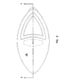
- FIGs. 1 and 2 show apparatus 20 of the present invention with a device known as a gravity-feed, water filtration carafe 22.
- Apparatus 20 is preferably removably mounted in a container 21 having a wall 23 as a floor of an upper reservoir 24 in a detent 25, preferably adapted to the shape of apparatus 20.
- Apparatus 20 includes a peripheral rim 26, cooperatingly shaped in accordance with the shape of detent 25.
- Water is poured into upper reservoir 24 by removing the lid 28 of carafe 22.
- Water passes through apparatus 20 and activates a float 30, which is rotationally mounted on a threaded rod 32, such that the float 30 rotates and moves toward an inverted terminal position (shown in phantom).
- the float 30, as rotated and shown in phantom is indicative of the end of life for apparatus 20. After passing float 30, the water is treated, prior to entering the lower reservoir 34.
- a housing 40 is attached to a conventional water treatment unit or cartridge 42, preferably forming an integral item.
- Cartridge 42 includes a holder 43 which preferably holds liquid treatment resin such as activated carbon, but may be designed to hold alternatively mechanical filters or other water purifying mechanisms.
- Cartridge 42 can be disposable or refillable or the like, such types of cartridges being commercially available.
- Housing 40 includes an opening 46 and an air hole 48 along its top 49. Opening 46 and air hole 48 allow water to enter a chamber 50 formed by the top interior of housing 40 and the top of cartridge 42.
- Housing top 49 includes two inclined sections 52, 53, both inclined toward opening 46.
- Air hole 48 is in inclined section 53.
- Inclined section 52 is preferably at or below the level of the wall 23, functioning as the floor of upper reservoir 24 (FIG. 1) of carafe 22 (FIG. 1). In that way, the maximum amount of water poured into upper reservoir 24 (FIG. 1) can enter housing 40 through opening 46.
- Inclined sections 52, 53 are preferably inclined at approximately 5 degrees, so that the air hole 48 is above the level of wall 23 (FIG. 1) of the upper reservoir 24 (FIG. 1). As chamber 50 empties of water, air escapes from hole 48 to relieve the pressure in chamber 50 which then allows float 30 to function properly.
- Float 30 is a member which is rotationally mounted on a threaded rod 32. Threaded rod 32 terminates in an end member 58 mounted to a sidewall 60 of housing 40. End member 58 is essentially a bracket for holding rod 32 with respect to housing 40. Once float 30 has traveled a distance D on the threaded rod 32, it comes to rest in an inverted terminal position against a ledge 62. Ledge 62 protrudes from end member 58. Float 30 in this inverted terminal position (FIG. 3, shown in phantom in FIG. 4), rests against ledge 62, such that its indicator (bottom) surface 63 can be viewed through opening 46.
- Indicator surface 63 is preferably red or other color which provides a sharp contrast to the color of the housing top 49. Accordingly, when float 30 has reached the inverted terminal position, the user is alerted that the cartridge is spent, or nearly spent, and should be attended to, by refilling, replacing, or otherwise revitalizing the cartridge, depending on the type of cartridge employed. If float 30 has not reached this inverted terminal position, the viewer will see the threaded rod 32 or a portion of float 30 in an upright (also known as the standard or starting) position on the threaded rod 32.
- Float 30 when float 30 has reached this inverted terminal position, the distance between the top 49 of the housing 40 and the indicator surface 63 is very small. Float 30 in that position, thus also acts as a flow restrictor for water flow into chamber 50 thereby impeding subsequent flow of water through the cartridge 42, such that product, i.e., purified water, coffee, juice, etc., would be produced at an exceedingly slow rate, indicating to the user that the cartridge 42 is spent and should be attended to.
- Air hole 48 is of a small enough diameter, such that the surface tension of the water across it prevents fluid entry.
- Housing 40 includes a tab 64 which the user holds when removing apparatus 20 from carafe 22 or separating housing 40 and cartridge 42, if housing 40 is designed to be separable from cartridge 42. If housing 40 is separable from cartridge 42, float 30 can be reset by either winding it backwards along threaded rod 32 or by sliding float 30 along the threaded rod 32, away from end member 58. If float 30 and rod 32 are made with sufficient clearance between the major diameter of the threaded rod 32 and the minor diameter of the threaded portion 76 of the float 30 (FIG. 7), float 30 can be slid with respect to rod 32 even though both are threaded.
- Threaded rod 32 is pitched in proportion to the lifetime of cartridge 42. For example, if cartridge 42 functions for a predetermined number of cycles (uses), the length and pitch of threaded rod 32 is such that float 30 (which makes one revolution per cycle) will reach ledge 62 and rest in the inverted position when the last cycle (effective use) of the cartridge 42 has been completed.
- Cartridge 42 includes a holder 43 with an inclined grate 66 at its upper end engaged with shoulders 67 cut into inner wall 68. Inclined grate 66, when combined with housing 40 serves as the bottom of chamber 50. Although an inclined grate 66 is preferred, various angles of inclination for grate 66 as well as a flat grate are also permitted.
- the lower end of cartridge 42 is also formed as a grate 69. Both grates 66, 69 include openings sized to retain the resin or other water purifying material cartridge 42, so it can not leave and enter the water.
- One or both of upper and lower grates 66, 69 may be removable from holder 43, in order that cartridge 42 be refilled or rejuvenated. Alternately, upper and lower gates 66, 69 may be permanently attached to holder 43, by adhesive bonding, sonic welding or the like, such that the cartridge is disposable.
- Cartridge 42 is preferably made of plastic, although other suitable materials are also permissible.
- Housing 40 is preferably made of plastic and can be attached in a permanent or removable manner to cartridge 42. If a permanent attachment is desired, housing 40 is glued, sonic welded, bonded or the like to cartridge 42, such that an integral unit, like that shown, is formed. If a removable attachment is desired, housing 30 can be placed onto cartridge 42 by mechanical fasteners such as clips, snaps, latches, friction fits or the like.
- housing 40 can be remote from cartridge 42, provided chamber 50 (formed by the interior of the housing) can fill completely with liquid in order that float 30 functions properly.
- Cartridge 42 could be either upstream or downstream of housing 40, depending on the particular apparatus.
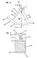
- FIGS. 6 and 7 show a detailed view of float 30.
- Float 30 includes a body 72, formed of a ring member 74.
- Ring member 74 includes a center point C and has a threaded portion 76 along its inner surface 77, to engage threaded rod 32 (FIGs. 1 and 3-5).
- Arms 78, 79 extend from ring member 74 and terminate in a cross-member 82 having an indicator surface 63.
- Cross-member 82 and indicator surface 63 extend from an elbow 84 to beyond arm 78 via a finger 86.
- Indicator surface 63 is at a constant radius from the center point C.
- Arms 78, 79 and finger 86 are bounded by a common wall 87. This wall 87 is flat and is oriented such that it faces sidewall 60 of housing 40, but will not accidentally rest on ledge 62 until float 30 has made the maximum number of rotations, traveling the maximum distance D (illustrated in FIG. 4).
- Arms 78, 79 are of different thicknesses, and a portion of cross-member 82 leading to finger 86 is of a different thickness than the remainder of the cross-member 82. These characteristics are related to the buoyancy and weight of the float 30, which is discussed below.
- a central panel 88 fits within the inside of body 72, bordered by arms 78, 79 and cross member 82. This central panel 88 is additionally secured within the inside of body 72 by a spacer 90 protruding from arm 79.
- Body 72 is made of a material such as Acrylonitrile Butadiene Styrene (ABS) or the like. It is preferably an integral piece made by techniques such as injection molding or the like.
- central panel 88 is an integral piece of closed cell foam or other equivalent material attached to body 72 by adhesive or other equivalent fastening techniques. It is preferred that the material of body 72 have a density near that of the water and the central panel 88 have a small density such that it may provide the buoyant force required, in order that float 30 functions properly.
- ABS for body 72 has a density of approximately 1.05 gm/cm 3 while density of the closed cell foam for the central panel 88 has a density of approximately 0.01 gm/cm 3 .
- apparatus 20 operates as water flows into housing 40 and specifically chamber 50 during each treatment cycle (use). Initially, chamber 50 containing float 30 is empty, and float 30 is in an upright (starting) position on threaded rod 32.
- Float 30 is designed such that it becomes buoyant as chamber 50 fills with water, preferably completely. Filling occurs since the openings in grates 66, 68, as well as the water purifying media slow the water flow rate by virtue of frictional impediment or pressure drop. That is, on pouring water into upper reservoir 24 (FIG. 1), sufficient water remains in upper reservoir 24 (FIG. 1) to as to immerse chamber 50 until the water can flow through to housing 40 and cartridge 42. Once buoyant, and then on emptying of the water from chamber 50, float 30 rotates one turn.
- the center of gravity of float 30 is on a vertical line passing through the axis of rod 32.
- a center of buoyancy of float 30 develops, whose location depends on the particular geometry of water displaced by float 30. It is important, however, that the center of buoyancy be spaced to the side of the vertical on which the center of gravity lies which allows the buoyant force to create a torque for advancing float 30 along rod 32 in the desired direction. The torque due to the buoyant force dominates and moves the float until an equilibrium is established between the gravitational and buoyant forces when fully submersed.
- a cycle comprises sufficient filling of chamber 50 and then emptying of it so as to cause float 30 to rotate as indicated.
- float 30 When float 30 has rotated through the maximum number of cycles corresponding to the life time of cartridge 42, float 30 impacts ledge 62 at a point when float 30 is in the inverted position so as to provide an appropriate visual indication through opening 46 and also to substantially close opening 46.
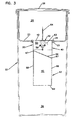
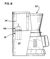
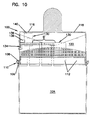
- FIGs. 8-10 show second apparatus 100 of the present invention for use with a coffee maker 22' or alternately, the carafe 22 described in FIGs. 1-3 and 5 above.
- Apparatus 100 is the same as apparatus 20 described in FIGs. 1-7 above except as indicated below.
- Apparatus 100 includes a housing 102 which is preferably rounded, and housing 102 extends substantially into upper reservoir 24' of coffee maker 22'. Housing 102 attaches to cartridge 104, similar to that described in FIGs. 1, 3 and 4 above, along a protruding rim 106, extending around its upper periphery. This protruding rim 106 is received by a peripheral claw 108 that extends around the lower periphery of housing 102. This peripheral claw 108 frictionally engages protruding rim 106, forming a rim/claw assembly 110.
- Cartridge 104 is received in a pocket 25', preferably configured to the shape of cartridge 104.
- the pocket 25' forms a wall between the upper reservoir 24' and the lower reservoir 34', where the water is heated prior to being made into coffee.
- the rim/claw assembly 110 is then received in detent 25 in floor 23 of upper reservoir 24 of carafe 22, to properly retain apparatus 100 in carafe 22.
- Housing 102 preferably includes slitted openings 112 at the sides, as well an opening 116 and an air hole 118 at the top. Openings 112, 116 and hole 118 allow water to enter (and leave) a chamber 120 formed by the interior of housing 102 and cartridge 104. Slitted openings 112 are necessary since chamber 120 and housing 102 extend upwardly into reservoir 24'. Openings 112 allow complete drainage of reservoir 24'.
- Float 130 is rotationally mounted on threaded rod 132 within chamber 120. Threaded rod 132 terminates in end member 134, mounted as a bracket to a sidewall 136 of housing 102. Opening 116 provides a view into chamber 120 for observing the position of float 130. Housing 102 includes a tab 137 which the user holds when removing apparatus 100 from coffee maker 22' or separating housing 102 and cartridge 104 (if housing 102 is designed to be removable from cartridge).
- float 130 Once float 130 has traveled a distance D' on threaded rod 132, it comes to rest against a ledge 138, which protrudes from end member 134. Float 130 in this inverted terminal position (FIG. 9, shown in phantom in FIG. 10), rests against ledge 138, such that its indicator (or bottom) surface 140 can be viewed through opening 116.
- This indicator surface 140 is preferably red or other color which provides a sharp contrast to the color of the top of the housing 102. Accordingly, the user is now alerted that the cartridge is spent, or nearly spent, and should be attended to, by refilling, replacing, or otherwise revitalizing it, depending on the type of cartridge employed.
- Float 130 and threaded rod 132 are identical in all aspects to float 30 and threaded rod 32 detailed in FIGs. 1-7 above. Accordingly, float 130 and threaded rod 132 are configured in accordance with the respective float 30 and threaded rod 32 described in FIGs. 1-7 above, in order to operate identically to that of the first apparatus 20 described above.
- Housing 102 is preferably made of plastic and can be attached in a removable or permanent manner to cartridge 104. If a removable attachment is desired, like the friction fit detailed above, claw 108 or other equivalent structure of housing 102 can be placed onto protruding rim 106, or other equivalent structure of cartridge 104 by mechanical fasteners such as clips, snaps, latches, or the like. If a permanent attachment is desired, housing 102 is glued, sonic welded, bonded or the like to cartridge 104.
- the cartridge 104 includes a holder 143 with an inclined grate 146 at its upper end, which when combined with housing 102 serves as the bottom of chamber 120. Although an inclined grate 146 is preferred, various angles of inclination for grate 146 as well as a flat grate are also permitted.
- the lower end of cartridge 104 is also formed as a grate 148. Both grates 146, 148 include openings sized to retain resin or other water purifying material in cartridge 104, so it can not leave and enter the water. One or both of upper and lower grates 146, 148 may be removable from holder 143 in order that cartridge 104 be refilled or rejuvenated.
- upper and lower grates 146, 148 may be permanently attached to holder 143, by adhesive bonding, sonic welding or the like, such that cartridge 104 is disposable.
- Cartridge 104 is preferably made of plastic, although other suitable materials are also permissible.
Landscapes
- Physics & Mathematics (AREA)
- General Physics & Mathematics (AREA)
- Life Sciences & Earth Sciences (AREA)
- Hydrology & Water Resources (AREA)
- Engineering & Computer Science (AREA)
- Environmental & Geological Engineering (AREA)
- Water Supply & Treatment (AREA)
- Chemical & Material Sciences (AREA)
- Organic Chemistry (AREA)
- Water Treatment By Sorption (AREA)
- Treatment Of Water By Ion Exchange (AREA)
Applications Claiming Priority (3)
| Application Number | Priority Date | Filing Date | Title |
|---|---|---|---|
| US08/341,420 US5536394A (en) | 1994-11-17 | 1994-11-17 | End of life mechanism for water treatment cartridge |
| US341420 | 1994-11-17 | ||
| PCT/US1995/014519 WO1996015994A1 (en) | 1994-11-17 | 1995-11-13 | End of life mechanism for water treatment cartridge |
Publications (2)
| Publication Number | Publication Date |
|---|---|
| EP0792249A1 EP0792249A1 (en) | 1997-09-03 |
| EP0792249B1 true EP0792249B1 (en) | 1999-08-04 |
Family
ID=23337490
Family Applications (1)
| Application Number | Title | Priority Date | Filing Date |
|---|---|---|---|
| EP95942847A Expired - Lifetime EP0792249B1 (en) | 1994-11-17 | 1995-11-13 | End of life mechanism for water treatment cartridge |
Country Status (15)
| Country | Link |
|---|---|
| US (2) | US5536394A (enExample) |
| EP (1) | EP0792249B1 (enExample) |
| JP (1) | JP3877331B2 (enExample) |
| KR (1) | KR100375414B1 (enExample) |
| CN (1) | CN1087274C (enExample) |
| AU (1) | AU4406196A (enExample) |
| BR (1) | BR9509697A (enExample) |
| CA (1) | CA2203439C (enExample) |
| DE (1) | DE69511282T2 (enExample) |
| IL (1) | IL115974A (enExample) |
| RU (1) | RU2145252C1 (enExample) |
| TR (1) | TR199501454A2 (enExample) |
| TW (1) | TW301613B (enExample) |
| WO (1) | WO1996015994A1 (enExample) |
| ZA (1) | ZA959742B (enExample) |
Families Citing this family (88)
| Publication number | Priority date | Publication date | Assignee | Title |
|---|---|---|---|---|
| PL180198B1 (pl) * | 1994-10-28 | 2000-12-29 | Laica Srl | Naczynie do filtrowania cieczy, zwlaszcza wody pitnej PL |
| US5536394A (en) * | 1994-11-17 | 1996-07-16 | Recovery Engineering, Inc. | End of life mechanism for water treatment cartridge |
| JPH09120238A (ja) * | 1995-10-25 | 1997-05-06 | Canon Inc | 出力装置 |
| USD385945S (en) | 1996-01-29 | 1997-11-04 | Braun Aktiengesellschaft | Water filter |
| USD386041S (en) * | 1996-04-30 | 1997-11-11 | Recovery Engineering, Inc. | Water purification pitcher |
| US5882507A (en) | 1996-04-30 | 1999-03-16 | Recovery Engineering, Inc. | Water filter cartridge end-of-life mechanism |
| US6290848B1 (en) | 1997-04-16 | 2001-09-18 | Pur Water Purification Products, Inc. | Filter cartridge for gravity-fed water treatment devices |
| USD399141S (en) | 1997-05-06 | 1998-10-06 | The Clorox Company | End-of-life indicator for a water treatment device |
| US5873995A (en) * | 1997-05-06 | 1999-02-23 | The Clorox Company | End-of-life indicator for water treatment device |
| US6149801A (en) | 1997-08-08 | 2000-11-21 | Water Pik, Inc,. | Water treatment device with volumetric monitoring features |
| US5935426A (en) | 1997-08-08 | 1999-08-10 | Teledyne Industries, Inc., A California Corporation | Water treatment device with volumetric and time monitoring features |
| RU2125974C1 (ru) * | 1997-08-21 | 1999-02-10 | Закрытое акционерное общество "АКВАФОР" | Способ фильтрационной очистки жидкости и фильтр для очистки жидкости |
| US6387260B1 (en) | 1997-08-21 | 2002-05-14 | Electrophor, Inc. | Filtration device for liquid purification |
| USD406003S (en) * | 1997-11-10 | 1999-02-23 | Recovery Engineering, Inc. | Water purification pitcher |
| ITPD980030A1 (it) | 1998-02-16 | 1999-08-16 | Laica Srl | Dispositivo di intercettazione del flusso di un fluido attraverso un passaggio, preferibilmente in un sistema di filtraggio per acqua po |
| USD406536S (en) * | 1998-02-23 | 1999-03-09 | The Clorox Company | End-of-life indicator for a water treatment device |
| US6042725A (en) * | 1998-04-20 | 2000-03-28 | Matscorp Ltd. | Water filter cartridge |
| US6033557A (en) * | 1998-06-02 | 2000-03-07 | Gebhard; Albert W. | Filter use limitation device for liquid containers |
| US6066252A (en) * | 1998-09-01 | 2000-05-23 | Reeves; Gary R. | Alarm mechanism for chlorinator in aerobic waste treatment system |
| US6287456B1 (en) | 1998-10-30 | 2001-09-11 | Kimberly-Clark Worldwide, Inc. | Filtration system with filtrate volume indicator |
| US6274041B1 (en) | 1998-12-18 | 2001-08-14 | Kimberly-Clark Worldwide, Inc. | Integrated filter combining physical adsorption and electrokinetic adsorption |
| US6537614B1 (en) | 1998-12-18 | 2003-03-25 | Kimberly-Clark Worldwide, Inc. | Cationically charged coating on hydrophobic polymer fibers with poly (vinyl alcohol) assist |
| USD439790S1 (en) | 1999-04-16 | 2001-04-03 | Matscorp Ltd. | Water pitcher |
| CZ20014131A3 (cs) * | 1999-05-20 | 2002-08-14 | The Procter & Gamble Company | Způsob odstraňování nejdrobnějąích patogenů z kapaliny |
| USD450531S1 (en) | 1999-06-29 | 2001-11-20 | Kimberly-Clark Worldwide, Inc. | Carafe for filtered water |
| USD444987S1 (en) | 1999-06-29 | 2001-07-17 | Kimberly-Clark Worldwide, Inc. | Filtered water carafe |
| AU6115000A (en) | 1999-07-21 | 2001-02-13 | Procter & Gamble Company, The | Microorganism filter and method for removing microorganism from water |
| DE19953376C1 (de) * | 1999-11-06 | 2001-07-05 | Braun Gmbh | Erfassungsvorrichtung |
| USD444662S1 (en) | 1999-11-09 | 2001-07-10 | Kimberly-Clark Worldwide, Inc. | Filtered water pitcher |
| US6645388B2 (en) | 1999-12-22 | 2003-11-11 | Kimberly-Clark Corporation | Leukocyte depletion filter media, filter produced therefrom, method of making same and method of using same |
| US6942674B2 (en) * | 2000-01-05 | 2005-09-13 | Integrated Vascular Systems, Inc. | Apparatus and methods for delivering a closure device |
| RU2189271C2 (ru) * | 2000-01-21 | 2002-09-20 | Общество с ограниченной ответственностью "Аквафор" | Механизм индикации конца срока службы модуля фильтра |
| FR2806897B1 (fr) * | 2000-03-29 | 2003-05-30 | Moulinex Sa | Appareil electromenager comportant une cartouche amovible de traitement d'eau |
| USD440110S1 (en) | 2000-03-29 | 2001-04-10 | Recovery Engineering, Inc. | Water purification pitcher |
| RU2181615C1 (ru) * | 2001-04-17 | 2002-04-27 | Общество с ограниченной ответственностью "Аквафор" | Устройство определения ресурса работы модуля фильтра |
| RU2184598C1 (ru) * | 2001-05-03 | 2002-07-10 | Общество с ограниченной ответственностью "Аквафор" | Способ определения ресурса работы фильтрующего устройства |
| US20030034283A1 (en) * | 2001-08-17 | 2003-02-20 | Tsataros Eddie J. | Fluid treatment device and counter mechanism |
| US20030217967A1 (en) * | 2001-08-23 | 2003-11-27 | The Procter & Gamble Company | Processes for manufacturing water filter materials and water filters |
| US20050279696A1 (en) * | 2001-08-23 | 2005-12-22 | Bahm Jeannine R | Water filter materials and water filters containing a mixture of microporous and mesoporous carbon particles |
| US7614508B2 (en) * | 2001-08-23 | 2009-11-10 | Pur Water Purification Products Inc. | Water filter materials, water filters and kits containing silver coated particles and processes for using the same |
| KR100777951B1 (ko) * | 2001-08-23 | 2007-11-28 | 더 프록터 앤드 갬블 캄파니 | 정수 필터 재료, 대응하는 정수 필터 및 그의 사용 방법 |
| US7615152B2 (en) | 2001-08-23 | 2009-11-10 | Pur Water Purification Products, Inc. | Water filter device |
| US7614507B2 (en) * | 2001-08-23 | 2009-11-10 | Pur Water Purification Products Inc. | Water filter materials, water filters and kits containing particles coated with cationic polymer and processes for using the same |
| US7258781B2 (en) * | 2002-09-09 | 2007-08-21 | Clarity Filters Llc | Single-use long-life faucet-mounted water filtration devices |
| US7252757B2 (en) * | 2002-09-09 | 2007-08-07 | Clarity Filters Llc | Faucet-mounted water filtration device including gate position sensor |
| USD498512S1 (en) | 2003-07-03 | 2004-11-16 | Clear Flow Corporation | Water filter |
| USD533622S1 (en) | 2003-10-01 | 2006-12-12 | Water Pik, Inc. | End-of-faucet filter |
| US7326334B2 (en) | 2003-10-01 | 2008-02-05 | Instapure Brands, Inc. | End-of-faucet filter |
| US7438799B2 (en) * | 2003-12-03 | 2008-10-21 | Headwaters R & D, Inc. | Portable, refillable water dispenser serving batches of water purified of organic and inorganic pollutants |
| US7713482B2 (en) | 2003-12-18 | 2010-05-11 | The Clorox Company | Control scheme for enhanced filtered water systems |
| US7378015B2 (en) * | 2003-12-18 | 2008-05-27 | The Clorox Company | Filtered water enhancements |
| ITPD20040095A1 (it) * | 2004-04-08 | 2004-07-08 | Laica Srl | Caraffa filtrante a cartuccia sostituibile |
| US7107838B2 (en) * | 2004-04-19 | 2006-09-19 | Fook Tin Technologies Ltd. | Apparatus and methods for monitoring water consumption and filter usage |
| US7487677B2 (en) * | 2004-04-19 | 2009-02-10 | Fook Tin Technologies Ltd. | Apparatus and methods for monitoring water consumption and filter usage |
| US7316323B2 (en) * | 2004-05-06 | 2008-01-08 | The Procter & Gamble Company | Filters having improved permeability and virus removal capabilities |
| US20050258082A1 (en) * | 2004-05-24 | 2005-11-24 | Lund Mark T | Additive dispensing system and water filtration system |
| US8556127B2 (en) * | 2004-05-24 | 2013-10-15 | Pur Water Purification Products, Inc. | Additive dispensing system for a refrigerator |
| US7670479B2 (en) | 2004-05-24 | 2010-03-02 | PUR Water Purification, Inc. | Fluid container having an additive dispensing system |
| US8893927B2 (en) * | 2004-05-24 | 2014-11-25 | Pur Water Purification Products, Inc. | Cartridge for an additive dispensing system |
| GB0427825D0 (en) * | 2004-12-17 | 2005-01-19 | Strix Ltd | Water treatment vessels and cartridges therefor |
| US20060175317A1 (en) * | 2005-02-09 | 2006-08-10 | Senno Technology Inc. | Lifespan monitoring apparatus and method for a filter of an unboiled water pitcher |
| WO2006107890A1 (en) * | 2005-04-01 | 2006-10-12 | Applica Consumer Products, Inc. | Water filtration system with improved performance |
| US7537695B2 (en) * | 2005-10-07 | 2009-05-26 | Pur Water Purification Products, Inc. | Water filter incorporating activated carbon particles with surface-grown carbon nanofilaments |
| USD541372S1 (en) | 2005-11-01 | 2007-04-24 | Clarity Filters Llc | Water filter |
| US7297283B2 (en) * | 2005-12-09 | 2007-11-20 | Yakima Filters, Inc. | Container having fluid purification system |
| US8790512B2 (en) * | 2006-10-08 | 2014-07-29 | Strauss Water Ltd. | Fluid filter monitoring device |
| US7767087B2 (en) * | 2007-01-05 | 2010-08-03 | Wilson Kelce S | Floating filter holder |
| USD583612S1 (en) | 2007-05-21 | 2008-12-30 | Applica Consumer Products, Inc. | Water filtration pitcher |
| US8043502B2 (en) | 2007-08-29 | 2011-10-25 | Uv Corporation | Water pitcher filter |
| US20090057241A1 (en) * | 2007-08-29 | 2009-03-05 | Phillip Nauta | Filter assembly |
| MD3805C2 (ro) * | 2007-12-26 | 2009-08-31 | ШКИЛЁВ Думитру Владимир | Filtru pentru purificarea apei |
| US8940163B2 (en) * | 2008-07-21 | 2015-01-27 | 3M Innovative Properties Company | Apparatus for dispersing additive into a fluid stream |
| US8336292B2 (en) | 2008-11-12 | 2012-12-25 | Caterpillar Inc. | Exhaust component having permanently associated life indicator |
| US8128820B2 (en) * | 2009-02-25 | 2012-03-06 | Mr. Chiaphua Industries Limited | UV liquid storage and dispensing device |
| SG10201403779RA (en) | 2009-09-09 | 2014-10-30 | Strauss Water Ltd | Liquid filter device |
| US20130193060A1 (en) * | 2010-08-12 | 2013-08-01 | Mitsubishi Rayon Cleansui Company, Limited | Water purification cartridge |
| USD676766S1 (en) | 2011-05-10 | 2013-02-26 | Brita Lp | Filter indicator |
| US8961781B2 (en) | 2011-09-29 | 2015-02-24 | Brita Lp | Filter status techniques adapted for use with a container based filtration device |
| EP2791061B1 (en) | 2011-12-16 | 2022-06-15 | Helen of Troy Limited | Gravity filter |
| US10669163B2 (en) | 2012-10-24 | 2020-06-02 | Paragon Water Systems | Universal filter cartridge |
| RU2527854C2 (ru) * | 2012-11-30 | 2014-09-10 | Государственное бюджетное образовательное учреждение высшего прфессионального образования "Кировская государственная медицинская академия" Министерства здравоохранения Российской Федерации (ГБОУ ВПО Кировская ГМА Минздрава России) | Способ в.г. вохмянина определения окончания срока годности картриджей автономных устройств для обработки подаваемой самотеком воды (варианты). |
| US9937446B1 (en) * | 2013-08-06 | 2018-04-10 | Brita Lp | Mechanisms and systems for directing water flow in a fluid container |
| WO2015042844A1 (zh) * | 2013-09-26 | 2015-04-02 | 深圳市兴日生实业有限公司 | 有滤芯堵塞警示的水过滤器和警示方法 |
| BR112016029257A2 (pt) | 2014-06-20 | 2017-08-22 | Unilever Nv | dispositivo de medição para um conjunto de autodesligamento |
| EP3274066B1 (en) | 2015-03-23 | 2020-04-22 | Strauss Water Ltd | Water filter and assembly thereof |
| DE102018103385B4 (de) * | 2018-02-15 | 2019-12-05 | Bwt Ag | Deckel mit einer Wechselanzeige |
| US11872506B2 (en) * | 2018-07-07 | 2024-01-16 | Paragon Water Systems, Inc. | Water filter cartridge having an air vent |
| USD964795S1 (en) | 2020-09-28 | 2022-09-27 | Brita Lp | Water pitcher |
Family Cites Families (25)
| Publication number | Priority date | Publication date | Assignee | Title |
|---|---|---|---|---|
| US815102A (en) * | 1905-02-23 | 1906-03-13 | James Edward Lea | Liquid-plow measurer and recorder. |
| US871253A (en) * | 1906-02-20 | 1907-11-19 | Charles W Bauman | Measuring-faucet. |
| US2605931A (en) * | 1949-03-17 | 1952-08-05 | Eustace S Scannell | Beverage control system and dispensing means |
| US2669707A (en) * | 1950-04-29 | 1954-02-16 | Bowser Inc | Filter signal |
| US3687289A (en) * | 1970-09-04 | 1972-08-29 | Ecodyne Corp | Water softener system |
| DE3413948A1 (de) * | 1984-04-13 | 1985-10-24 | Heinz 6204 Taunusstein Hankammer | Vorrichtung zum wasserreinigung |
| US4698164A (en) * | 1985-07-29 | 1987-10-06 | Kinetico, Inc. | Filter apparatus |
| US4650571A (en) * | 1985-11-29 | 1987-03-17 | H. R. Black Company | Automatic indexer for industrial filters |
| DE3810441C2 (de) * | 1988-03-26 | 1994-09-08 | Brita Wasserfilter | Wasserreinigungsvorrichtung mit einem Einlauftrichter |
| DE8805718U1 (de) * | 1988-04-30 | 1988-07-21 | Brita Wasser-Filter-Systeme Gmbh, 6204 Taunusstein | Siebdeckel für einen Reinigungseinsatz in einer Wasseraufbereitungsvorrichtung mit einem Hohlrohr |
| US5089144B1 (en) * | 1989-12-08 | 1996-11-12 | Nartron Corp | Filter condition indicator having moveable sensor and aggregate flow counter |
| US4998228A (en) * | 1990-02-09 | 1991-03-05 | Douglas R. Eger | Drinking water filter |
| US4986901A (en) * | 1990-02-12 | 1991-01-22 | Innova Pure Water Inc. | Bottled water cap with indicator and adaptor |
| JPH0655307B2 (ja) * | 1990-03-30 | 1994-07-27 | 松下電器産業株式会社 | 濾過器 |
| US5065901A (en) * | 1990-04-09 | 1991-11-19 | Brane Earl P | Apparatus for monitoring a flow of fluid through a filter medium |
| US5139666A (en) * | 1991-01-04 | 1992-08-18 | Domotechnica Canada, Inc. | Bottle and filter |
| US5057821A (en) * | 1991-02-19 | 1991-10-15 | Card Gary C | Filter sentry apparatus |
| US5128034A (en) * | 1991-03-21 | 1992-07-07 | Amway Corporation | Pressure vessel for housing a water filter |
| US5190643A (en) * | 1992-01-10 | 1993-03-02 | Mr. Coffee, Inc. | Water treatment device having means to count times used and limit useage |
| US5236578A (en) * | 1992-07-07 | 1993-08-17 | American Home Water Products Corporation | Filter life indicator for water purification system using magnetically actuated switch |
| US5328597A (en) * | 1992-07-27 | 1994-07-12 | The Clorox Corporation | Electronic monitoring unit for monitoring number of uses of cartridge |
| CA2098127C (en) * | 1993-06-10 | 1997-03-18 | Brian Feeney | Air inlet valve for water cooler |
| US5525214A (en) * | 1994-03-08 | 1996-06-11 | Recovery Engineering, Inc. | Filter cartridge for water treatment device |
| US5527451A (en) * | 1994-03-08 | 1996-06-18 | Recovery Engineering, Inc. | Water treatment device with volume totalization valve |
| US5536394A (en) * | 1994-11-17 | 1996-07-16 | Recovery Engineering, Inc. | End of life mechanism for water treatment cartridge |
-
1994
- 1994-11-17 US US08/341,420 patent/US5536394A/en not_active Expired - Lifetime
-
1995
- 1995-11-13 DE DE69511282T patent/DE69511282T2/de not_active Expired - Lifetime
- 1995-11-13 WO PCT/US1995/014519 patent/WO1996015994A1/en not_active Ceased
- 1995-11-13 KR KR1019970703320A patent/KR100375414B1/ko not_active Expired - Fee Related
- 1995-11-13 BR BR9509697A patent/BR9509697A/pt not_active IP Right Cessation
- 1995-11-13 CN CN95196257A patent/CN1087274C/zh not_active Expired - Fee Related
- 1995-11-13 EP EP95942847A patent/EP0792249B1/en not_active Expired - Lifetime
- 1995-11-13 RU RU97110105A patent/RU2145252C1/ru not_active IP Right Cessation
- 1995-11-13 JP JP51692396A patent/JP3877331B2/ja not_active Expired - Fee Related
- 1995-11-13 AU AU44061/96A patent/AU4406196A/en not_active Abandoned
- 1995-11-13 CA CA002203439A patent/CA2203439C/en not_active Expired - Fee Related
- 1995-11-14 IL IL11597495A patent/IL115974A/xx active IP Right Grant
- 1995-11-15 TW TW084112076A patent/TW301613B/zh active
- 1995-11-16 ZA ZA959742A patent/ZA959742B/xx unknown
- 1995-11-17 TR TR95/01454A patent/TR199501454A2/xx unknown
-
1996
- 1996-04-25 US US08/637,853 patent/US5785844A/en not_active Expired - Lifetime
Also Published As
| Publication number | Publication date |
|---|---|
| RU2145252C1 (ru) | 2000-02-10 |
| JPH10509378A (ja) | 1998-09-14 |
| CN1087274C (zh) | 2002-07-10 |
| US5785844A (en) | 1998-07-28 |
| CA2203439C (en) | 2008-02-26 |
| EP0792249A1 (en) | 1997-09-03 |
| ZA959742B (en) | 1997-05-16 |
| AU4406196A (en) | 1996-06-17 |
| CN1163601A (zh) | 1997-10-29 |
| JP3877331B2 (ja) | 2007-02-07 |
| IL115974A (en) | 1999-08-17 |
| US5536394A (en) | 1996-07-16 |
| DE69511282T2 (de) | 2000-04-13 |
| TR199501454A2 (tr) | 1996-06-21 |
| KR100375414B1 (ko) | 2003-05-16 |
| DE69511282D1 (de) | 1999-09-09 |
| WO1996015994A1 (en) | 1996-05-30 |
| CA2203439A1 (en) | 1996-05-30 |
| IL115974A0 (en) | 1996-01-31 |
| BR9509697A (pt) | 1997-09-30 |
| TW301613B (enExample) | 1997-04-01 |
Similar Documents
| Publication | Publication Date | Title |
|---|---|---|
| EP0792249B1 (en) | End of life mechanism for water treatment cartridge | |
| US9028690B2 (en) | Water treatment cartridge | |
| US4681677A (en) | Water processor having automatic shutoff and bypass means | |
| JP3677043B2 (ja) | 水処理装置 | |
| CA2288981C (en) | End-of-life indicator for water treatment device | |
| US5622618A (en) | Apparatus for monitoring cumulative flow of fluid through a filter medium | |
| US8480882B2 (en) | Water filter pitcher meter | |
| JP2000508972A (ja) | フィルカウントカートリッジを備えた水処理装置 | |
| UA68359C2 (en) | Apparatus and method for purifying water | |
| AU2007321500A1 (en) | Jug for filtering liquids | |
| WO2015192968A1 (en) | A metering device for an auto-shut off assembly | |
| JP2008542005A (ja) | 水および液体一般を濾過するための濾過装置 | |
| JP3371335B2 (ja) | 蛇口直結型浄水器 | |
| RU2335325C1 (ru) | Устройство для очистки воды | |
| RU2189271C2 (ru) | Механизм индикации конца срока службы модуля фильтра | |
| JP2007326028A (ja) | 浄水器 | |
| UA97472C2 (uk) | Фільтрувальний картридж для джбанів | |
| CA1184852A (en) | Water processor having fail-safe elements | |
| JPH0679265A (ja) | 浄水器 | |
| RU2173571C1 (ru) | Механизм индикации срока службы модуля устройства для очистки жидкости (варианты) и способ его использования | |
| WO2014192011A2 (en) | An auto shut off device for a water filter | |
| WO2018104036A1 (en) | A metering apparatus for an auto-shut off assembly | |
| HK1018769B (en) | Water treatment device with fill-counting cartridge | |
| HK1134416B (en) | Jug for filtering liquids | |
| MXPA99010258A (en) | End-of-life indicator for water treatment device |
Legal Events
| Date | Code | Title | Description |
|---|---|---|---|
| PUAI | Public reference made under article 153(3) epc to a published international application that has entered the european phase |
Free format text: ORIGINAL CODE: 0009012 |
|
| 17P | Request for examination filed |
Effective date: 19970502 |
|
| AK | Designated contracting states |
Kind code of ref document: A1 Designated state(s): DE FR GB |
|
| 17Q | First examination report despatched |
Effective date: 19971217 |
|
| GRAG | Despatch of communication of intention to grant |
Free format text: ORIGINAL CODE: EPIDOS AGRA |
|
| GRAG | Despatch of communication of intention to grant |
Free format text: ORIGINAL CODE: EPIDOS AGRA |
|
| GRAH | Despatch of communication of intention to grant a patent |
Free format text: ORIGINAL CODE: EPIDOS IGRA |
|
| GRAH | Despatch of communication of intention to grant a patent |
Free format text: ORIGINAL CODE: EPIDOS IGRA |
|
| GRAA | (expected) grant |
Free format text: ORIGINAL CODE: 0009210 |
|
| AK | Designated contracting states |
Kind code of ref document: B1 Designated state(s): DE FR GB |
|
| REF | Corresponds to: |
Ref document number: 69511282 Country of ref document: DE Date of ref document: 19990909 |
|
| ET | Fr: translation filed | ||
| PLBE | No opposition filed within time limit |
Free format text: ORIGINAL CODE: 0009261 |
|
| STAA | Information on the status of an ep patent application or granted ep patent |
Free format text: STATUS: NO OPPOSITION FILED WITHIN TIME LIMIT |
|
| 26N | No opposition filed | ||
| REG | Reference to a national code |
Ref country code: GB Ref legal event code: 732E |
|
| REG | Reference to a national code |
Ref country code: FR Ref legal event code: TP |
|
| REG | Reference to a national code |
Ref country code: GB Ref legal event code: IF02 |
|
| PGFP | Annual fee paid to national office [announced via postgrant information from national office to epo] |
Ref country code: DE Payment date: 20091130 Year of fee payment: 15 |
|
| PGFP | Annual fee paid to national office [announced via postgrant information from national office to epo] |
Ref country code: GB Payment date: 20091007 Year of fee payment: 15 Ref country code: FR Payment date: 20091120 Year of fee payment: 15 |
|
| GBPC | Gb: european patent ceased through non-payment of renewal fee |
Effective date: 20101113 |
|
| REG | Reference to a national code |
Ref country code: FR Ref legal event code: ST Effective date: 20110801 |
|
| REG | Reference to a national code |
Ref country code: DE Ref legal event code: R119 Ref document number: 69511282 Country of ref document: DE Effective date: 20110601 Ref country code: DE Ref legal event code: R119 Ref document number: 69511282 Country of ref document: DE Effective date: 20110531 |
|
| PG25 | Lapsed in a contracting state [announced via postgrant information from national office to epo] |
Ref country code: DE Free format text: LAPSE BECAUSE OF NON-PAYMENT OF DUE FEES Effective date: 20110531 |
|
| PG25 | Lapsed in a contracting state [announced via postgrant information from national office to epo] |
Ref country code: FR Free format text: LAPSE BECAUSE OF NON-PAYMENT OF DUE FEES Effective date: 20101130 |
|
| PG25 | Lapsed in a contracting state [announced via postgrant information from national office to epo] |
Ref country code: GB Free format text: LAPSE BECAUSE OF NON-PAYMENT OF DUE FEES Effective date: 20101113 |