EP0791982B1 - Verbinder mit doppelter Kontakthalterung - Google Patents
Verbinder mit doppelter Kontakthalterung Download PDFInfo
- Publication number
- EP0791982B1 EP0791982B1 EP97102918A EP97102918A EP0791982B1 EP 0791982 B1 EP0791982 B1 EP 0791982B1 EP 97102918 A EP97102918 A EP 97102918A EP 97102918 A EP97102918 A EP 97102918A EP 0791982 B1 EP0791982 B1 EP 0791982B1
- Authority
- EP
- European Patent Office
- Prior art keywords
- terminal
- retaining
- connector housing
- receiving chamber
- female
- Prior art date
- Legal status (The legal status is an assumption and is not a legal conclusion. Google has not performed a legal analysis and makes no representation as to the accuracy of the status listed.)
- Expired - Lifetime
Links
- 230000000717 retained effect Effects 0.000 title description 13
- 238000003780 insertion Methods 0.000 claims description 27
- 230000037431 insertion Effects 0.000 claims description 27
- 230000005489 elastic deformation Effects 0.000 claims description 8
- 238000012856 packing Methods 0.000 description 5
- 238000010276 construction Methods 0.000 description 4
- 229920003002 synthetic resin Polymers 0.000 description 4
- 239000000057 synthetic resin Substances 0.000 description 4
- 230000013011 mating Effects 0.000 description 2
- 238000000465 moulding Methods 0.000 description 1
- XLYOFNOQVPJJNP-UHFFFAOYSA-N water Substances O XLYOFNOQVPJJNP-UHFFFAOYSA-N 0.000 description 1
Images


Classifications
-
- H—ELECTRICITY
- H01—ELECTRIC ELEMENTS
- H01R—ELECTRICALLY-CONDUCTIVE CONNECTIONS; STRUCTURAL ASSOCIATIONS OF A PLURALITY OF MUTUALLY-INSULATED ELECTRICAL CONNECTING ELEMENTS; COUPLING DEVICES; CURRENT COLLECTORS
- H01R13/00—Details of coupling devices of the kinds covered by groups H01R12/70 or H01R24/00 - H01R33/00
- H01R13/40—Securing contact members in or to a base or case; Insulating of contact members
- H01R13/42—Securing in a demountable manner
- H01R13/436—Securing a plurality of contact members by one locking piece or operation
- H01R13/4364—Insertion of locking piece from the front
-
- H—ELECTRICITY
- H01—ELECTRIC ELEMENTS
- H01R—ELECTRICALLY-CONDUCTIVE CONNECTIONS; STRUCTURAL ASSOCIATIONS OF A PLURALITY OF MUTUALLY-INSULATED ELECTRICAL CONNECTING ELEMENTS; COUPLING DEVICES; CURRENT COLLECTORS
- H01R13/00—Details of coupling devices of the kinds covered by groups H01R12/70 or H01R24/00 - H01R33/00
- H01R13/46—Bases; Cases
- H01R13/52—Dustproof, splashproof, drip-proof, waterproof, or flameproof cases
- H01R13/5219—Sealing means between coupling parts, e.g. interfacial seal
- H01R13/5221—Sealing means between coupling parts, e.g. interfacial seal having cable sealing means
-
- H—ELECTRICITY
- H01—ELECTRIC ELEMENTS
- H01R—ELECTRICALLY-CONDUCTIVE CONNECTIONS; STRUCTURAL ASSOCIATIONS OF A PLURALITY OF MUTUALLY-INSULATED ELECTRICAL CONNECTING ELEMENTS; COUPLING DEVICES; CURRENT COLLECTORS
- H01R13/00—Details of coupling devices of the kinds covered by groups H01R12/70 or H01R24/00 - H01R33/00
- H01R13/62—Means for facilitating engagement or disengagement of coupling parts or for holding them in engagement
- H01R13/627—Snap or like fastening
- H01R13/6271—Latching means integral with the housing
- H01R13/6272—Latching means integral with the housing comprising a single latching arm
Definitions
- This invention relates to a double retaining connector in which each terminal is retained in a double manner by a retaining lance, provided within a connector housing, and a retaining arm of a front holder.
- FIG. 14 to 16 One conventional double retaining connector is shown in Figs. 14 to 16.
- the illustrated housing is a female one 102 of a pair of connector housings, and each female terminal 105, received in an associated terminal receiving chambers 102c in this female connector housing, is retained in a double manner by a retaining lance 102a, provided at an upper portion of the terminal receiving chamber 102c, and a front holder 103 attached to the female connector housing from the front side of the terminal receiving chambers 102.
- the plurality of terminal receiving chambers 102c are provided in two (upper and lower) rows in the female connector housing 102 made of a synthetic resin, and the retaining lance 102c is provided at an upper portion of each terminal receiving chamber 102c, and extends left (in the drawings) generally horizontally.
- the female terminal 105 inserted and guided into the terminal receiving chamber 102c from the right side (Fig.
- the front holder 103 like the female connector housing 102, is molded of a synthetic resin, and as shown in Figs. 14 and 15, the front holder 103 is attached to the female connector housing 102 from the front side of the terminal receiving chambers 102c of the female connector housing 102.
- a provisionally-retaining projection 103g formed on an upper retaining arm 103f, first slides past an upper retaining projection 102d of the female connector housing 102, and the front holder 103 is provisionally retained on the female connector housing 102.
- a distal end portion of the retaining arm 103a of the front holder 103 contacts an upper surface 102a 3 of the retaining lance 102a, thereby preventing the retaining lance 102a from upward movement, and therefore the female terminal 105 is retained in a double manner relative to the female connector housing 102.
- Fig. 15 shows a condition in which the female terminals 105 are retained in a double manner relative to the female connector housing 102.
- Right, left and lower slanting surfaces 102f are formed on a front end surface 102e of the lower terminal receiving chamber 102c of the female connector housing 102, and also a slanting surface 103b is formed on a front end surface 103h of the retaining arm 103a of the front holder 103, and these slanting surfaces 102f and 103b cooperate with one another to form a tapered guide portion 107 for an insertion port 106 through which a male terminal 104 is engaged with the female terminal 105.
- a front end portion 104a of the male terminal 104 is first guided into the insertion port 106 by the tapered guide portion 107, and is further moved into the terminal receiving chamber 102c in a direction of arrow D, and is engaged with the front end portion of the female terminal.
- the front end metallic portion 104a moves into the terminal receiving chamber 102c without being guided by the slanting surface 103b, and the distal end 104b of the front end portion 104a impinges on an upper portion of the front end surface of the front end portion (terminal portion) 105a of the female terminal 105, so that the male terminal 104 can not move further, and therefore the male terminal 104 can not be engaged with the female terminal 105.
- EP-A-374 492 according to the pre-characterising part of claim 1 discloses an electrical connector with a double terminal retaining mechanism.
- the connector comprises a connector housing having a terminal receiving chamber formed within said housing.
- a female terminal is inserted into the terminal receiving chamber.
- a retaining lance extends from an inner surface of the terminal receiving chamber which retains said female terminal by elastic deformation.
- a locking plate is attached to said connector housing from the same side as a male terminal is inserted into the female terminal.
- the front holder is fixed to the connector housing thereby preventing deformation of the terminal retaining lance and thus retaining the female terminal in a double manner.
- a retaining arm with a latching pawl is formed integrally with the locking plate which retains the locking plate on the connector by elastic deformation. Tapered guide portions formed as slanting surfaces are formed on said connector housing for guiding the male mating terminal.
- the present invention has been made in view of the problems of the above conventional double retaining connector, and an object of the invention is to provide a double retaining connector in which a male terminal can be smoothly inserted into a terminal receiving chamber by a tapered guide portion.
- Another object of the invention is to provide a double retaining connector in which a male terminal can be smoothly inserted into a terminal receiving chamber even when the male terminal to be inserted into an insertion portion abuts against any one of sides of a rectangular, tapered guide portion.
- a double retaining connector comprising a connector housing; a terminal receiving chamber formed within the connector housing, a female terminal being inserted into the terminal receiving chamber through one insertion portion thereof while a male terminal is inserted into the terminal receiving chamber through the other insertion portion thereof, and is engaged with the female terminal; a retaining lance which extends from an inner surface of the terminal receiving chamber, and retains the female terminal, received in the terminal receiving chamber, by elastic deformation; a front holder which is attached to the connector housing from that side of the terminal receiving chamber, through which the male terminal is inserted into the chamber, and is fixed to the connector housing, thereby preventing deformation of the retaining lance so as to retain the female terminal relative to the connector housing in a double manner; a retaining arm which is formed integrally with the front holder, and retains the front holder on the connector housing by elastic deformation; and a tapered guide portion for guiding the male terminal into the terminal receiving chamber, the tapered guide portion being formed by a
- the insertion portion of the terminal receiving chamber through which the male terminal is inserted into the terminal receiving chamber, has an opening of a generally rectangular cross-section, and the tapered guide portion is formed around the insertion portion in a generally rectangular shape, and at least part of sides of the tapered guide portion is formed by the slanting surface on the connector housing.
- the retaining arm which retains the front holder on the connector housing by elastic deformation, is deformable in the direction perpendicular to the direction of deformation of the retaining lance which retains the female terminal, received in the terminal receiving chamber, by elastic deformation. Therefore, the ratio of the slanting surface on the front holder to the tapered guide portion can be kept to a minimum.
- At least part of the sides of the rectangular, tapered guide portion is formed by the slanting surface on the connector housing. Therefore, even when the male terminal to be inserted into the insertion portion abuts against any of the sides of the rectangular, tapered guide portion, the male terminal abuts against the slanting surface on the connector housing which surface is not elastically deformable.
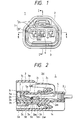
- Figs. 1 to 3 show one preferred embodiment of the double retaining connector of the invention.
- the double retaining connector 1 of the present invention like the above conventional double retaining connector 101, comprises a female connector housing 2 and a front holder 3, and further comprises a packing 14 forming a seal between the female connector housing 2 and the front holder 3.
- each female terminal 5 is retained in a double manner relative to the female connector housing 2 by a retaining lance 2a, provided in a terminal receiving chamber 2c of the female connector housing 2, and the front holder 3 attached to the female connector housing 2 from the rear side of the terminal receiving chambers 2c.
- Figs. 6 to 9 show the female connector housing 2.
- the female connector housing 2 is made of a synthetic resin, and has the plurality of terminal receiving chambers 2c provided within a tubular hood portion 2b for receiving the female terminals 5, respectively.
- Each terminal receiving chamber 2c has an insertion port 2j for the insertion of the female terminal 5 therethrough, and an insertion port 2k through which a male terminal 4 is inserted to be engaged with the female terminal 5.
- the retaining lance 2a extends left (in the drawings) generally horizontally from a lower surface of each terminal receiving chamber 2c, and a retaining end 2a 2 for engagement with a terminal metallic portion 5a of the female terminal 5 is formed on an upper end surface 2a 1 of the retaining lance 2a.
- a slanting surface 2h for guiding the insertion of the male terminal 4 into the terminal receiving chamber 2c is formed around the male terminal insertion port 2k of each terminal receiving chamber 2c. Because of the necessity of molding the retaining lance 2a, this slanting surface 2h can not be formed continuously over the entire periphery of the insertion port 2k, and cooperates with a slanting surface 3f (described later), formed on the front holder 3, to form a tapered guide portion 7 (Fig. 1).
- a provisionally-retaining projection 2e for engagement with a provisionally-retaining projection 3c on the front holder 3 is formed on a side wall.
- part of the side wall of the intermediate terminal receiving chamber 2c is notched to form an engagement portion 2f which is adapted to be engaged with a completely-retaining projection 3i (described later) of the front holder 3 to thereby fix the front holder 3 relative to the female connector housing 2.
- An elastic retaining arm 2d is formed on the female connector housing 2, and the female connector housing 2 is retained relative to a mating male connector housing (not shown) by this elastic retaining arm 2d.
- a packing insertion hole 2m for the insertion of the packing 14 therethrough is formed through a vertical wall 2n.
- the front holder 3 like the female connector housing 2, is molded of a synthetic resin, and an internal space of a frame 3j is partitioned by side walls 3k into spaces 3g which communicate respectively with the terminal receiving chambers 2c of the female connector housing 2 when the front holder 3 is attached to the female connector housing 2.
- a completely-retaining arm 3a formed integrally with a bottom portion 3m at a front end portion thereof, is in the form of a vertically-extending flat plate, and the completely-retaining projection 3i for engagement with the engagement portion 2f of the female connector housing 2 is formed on an upper edge of the completely-retaining arm 3a.
- a projection 3h is formed at a free end of the completely-retaining arm 3a, and the completely-retaining arm 3a is elastically deformed left (that is, in a direction of arrow B in Fig. 13) by this projection 3h.
- the slanting surface 3f is formed at the free end of the completely-retaining arm 3a, and cooperates with the slanting surface 2h of the female connector housing 2 to form the tapered guide portion 7.
- a provisionally-retaining arm 3b extends above the bottom plate 3m, and the provisionally-retaining projection 3c is formed on the provisionally-retaining arm 3b.
- This provisionally-retaining projection 3c performs its function when the front holder 3 is provisionally retained on the female connector housing 2.
- An end portion 3e is formed on a lower extension portion 3d of the completely-retaining arm 3a, and functions to cause the female terminal 5 to be retained relative to the female connector housing 2 in a double manner when the front holder 3 is completely retained on the female connector housing 2.
- the packing 14 is first attached to the female connector housing 2 through the packing insertion hole 2m, and then forms a seal between the female connector housing 2 and the front holder 3 to prevent water or the like from intruding from the exterior into the terminal receiving chambers 2c when the front holder 3 is attached to the female connector housing 2.
- the female terminal 5 is inserted into the terminal receiving chamber 2c of the female connector housing 2, and is fixed therein. More specifically, the female terminal 5, inserted through the female terminal insertion port 2j, moves in the terminal receiving chamber 2c, with a lower surface 5b of the terminal metallic portion 5a held in sliding contact with the upper end surface 2a 1 of the retaining lance 2a, and finally when an engagement end 5b 1 of a retaining hole in the lower surface 5b of the terminal metallic portion 5a passes past the retaining end 2a 2 of the retaining arm 2a, the retaining lance 2a in elastically restored to its initial position, thereby effecting a first-stage retaining of the female terminal 5 by the retaining lance 2a.
- the front holder 3 is attached to the female connector housing 2 from the front side of the terminal receiving chambers 2c of the female connector housing 2. More specifically, when the front holder 3 is inserted into the front end portion of the female connector housing 2, with its insertion-side end 3e first introduced into the female connector housing 2, the provisionally-retaining projection 3c, formed on the provisionally-retaining arm 3b, first slides past the provisionally-retaining projection 2e on the female connector housing 2, so that the front holder 3 is provisionally retained on the female connector housing 2.
- Fig. 4 shows the condition in which the female terminal 5 is retained relative to the female connector housing 2 in a double manner, and in this condition, the male terminal 4, received in the male connector housing (not shown) passes through an insertion port 6, formed in the front holder 3, and is brought into engagement with the female terminal 5. At this time, a front metallic end portion 4a of the male terminal 4 is guided into the insertion port 6 by the tapered guide portion 7 (Fig. 1), and is further inserted into the terminal receiving chamber 2c to be engaged with the front metallic end portion of the female terminal 5.
- the retaining arm 103a can be moved upward (that is, in the direction of arrow E) as shown in Fig. 16, and as a result, the front metallic end portion 104a moves into the terminal receiving chamber 102c without being guided by the tapered guide portion 103b, and the distal end 104b of the front end portion 104a impinges on the upper portion of the front end surface of the front end portion (terminal portion) 105a of the female terminal 105, so that the male terminal 104 can not move further, and therefore the male terminal 104 can not be engaged with the female terminal 105.
- the completely-retaining arm 3a is movable left (Fig. 5), that is, in the direction of arrow F, and therefore when the distal end 4b of the front metallic end portion 4a of the male terminal 4 abuts against the slanting surface 3f formed on the completely-retaining arm 3a, this slanting surface 3f is moved left, and therefore the front end portion 4a moves toward the insertion port 6 without being guided by the slanting surface 3f.
- the immovable slanting surface 2h on the housing is present in the vicinity of the slanting surface 3f on the front holder, the front metallic end portion 4a of the male terminal 4 is guided by this slanting surface 2h on the housing, so that the male terminal 4 can be engaged with the female terminal 5 without impingement of the distal end 4b of the front metallic end portion 4a upon the side wall of the female terminal 5 at the front end thereof.
- the ratio of the slanting surface on the front holder to the tapered guide portion for guiding the male terminal into the terminal receiving chamber can be kept to a minimum, and therefore the male terminal can be smoothly inserted into the terminal receiving chamber by the tapered guide portion.
- the male terminal to be inserted into the insertion portion abuts against any of the sides of the rectangular, tapered guide portion, the male terminal abuts against the slanting surface on the connector housing which surface is not elastically deformable, and therefore the male terminal can be smoothly inserted into the terminal receiving chamber by the tapered guide portion.
Landscapes
- Connector Housings Or Holding Contact Members (AREA)
- Details Of Connecting Devices For Male And Female Coupling (AREA)
Claims (2)
- Doppelrückhalte-Steckverbinder, umfassend:ein Steckverbindergehäuse (2);eine Anschlussklemme-Aufnahmekammer (2c), die innerhalb des Steckverbindergehäuses (2) ausgebildet ist, wobei eine Buchsenanschlussklemme (5) in die Anschlussklemme-Aufnahmekammer (2c) durch einen Einsteckbereich (2j) desselben einsteckt ist, während eine Steckeranschlussklemme (4) in die Anschlussklemme-Aufnahmekammer (2c) durch den anderen Einsteckbereich (2k) derselben eingesteckt ist und mit der Buchsenanschlussklemme (5) in Eingriff befindlich ist;eine Rückhaltelanze (2a), die sich von einer inneren Fläche der Anschlussklemme-Aufnahmekammer (2c) erstreckt und die Buchsenanschlussklemme (5), die in der Anschlussklemme-Aufnahmekammer (2c) aufgenommen wird, durch elastische Verformung zurückhält;eine Fronthalterung (3), welche an dem Steckverbindergehäuse (2) von einer Seite der Anschlussklemme-Aufnahmekammer (2c) her angebracht ist, durch welchen die Steckeranschlussklemme (4) in Kammer (2c) eingesteckt ist, und ist mit dem Steckverbindergehäuse (2) befestigt, wodurch eine Verformung der Rückhaltelanze (2a) verhindert wird, um die Buchsenanschlussklemme (5) relativ zu dem Steckverbindergehäuse (2) in einer zweifachen Weise zurückzuhalten;einen Rückhaltearm (3a), welcher einstückig mit der Fronthalterung (3) ausgebildet ist, und der die Fronthalterung (3) auf dem Steckverbindergehäuse (2) durch elastische Verformung zurückhält; undeinen sich verjüngenden Führungsbereich (7) zum Führen der Steckeranschlussklemme (4) in die Anschlussklemme (Aufnahmekammer) (2c) hinein, wobei der sich verjüngende Führungsbereich (7) als eine Schrägfläche (2h) ausgebildet ist, die auf dem Steckverbindergehäuse (2) ausgebildet ist, dadurch gekennzeichnet, dassder sich verjüngende Führungsbereich als eine weitere Schrägfläche (3f) ausgebildet ist, die im Einklang mit dem Rückhaltearm (3a) der Fronthalterung (3) bewegbar ist; undder Rückhaltearm (3a) in einer Richtung senkrecht zu einer Richtung der Verformung der Rückhaltelanze (2a) verformbar ist.
- Doppelrückhalte-Steckverhinder nach Anspruch 1, wobei der Einsteckbereich (2k) der Anschlussklemme-Aufnahmekammer (2c), durch welchen die Steckeranschlussklemme (4) in die Anschlussklemme-Aufnahmekammer (2c) einsteckbar ist, eine Öffnung mit einem im allgemeinen rechteckigen Querschnitt hat, und wobei der sich verjüngende Führungsbereich (7) um den Einsteckbereich (2c) herum in einer im allgemeinen rechteckigen Form ausgebildet ist, und wobei zumindest ein Teil der Seiten des sich verjüngenden Führungsbereiches (7) als Schrägfläche auf dem Steckverbindergehäuse (2) ausgebildet ist.
Applications Claiming Priority (3)
| Application Number | Priority Date | Filing Date | Title |
|---|---|---|---|
| JP36388/96 | 1996-02-23 | ||
| JP3638896 | 1996-02-23 | ||
| JP03638896A JP3244254B2 (ja) | 1996-02-23 | 1996-02-23 | 二重係止コネクタ |
Publications (3)
| Publication Number | Publication Date |
|---|---|
| EP0791982A2 EP0791982A2 (de) | 1997-08-27 |
| EP0791982A3 EP0791982A3 (de) | 1998-05-20 |
| EP0791982B1 true EP0791982B1 (de) | 2000-12-13 |
Family
ID=12468477
Family Applications (1)
| Application Number | Title | Priority Date | Filing Date |
|---|---|---|---|
| EP97102918A Expired - Lifetime EP0791982B1 (de) | 1996-02-23 | 1997-02-21 | Verbinder mit doppelter Kontakthalterung |
Country Status (5)
| Country | Link |
|---|---|
| US (1) | US6186813B1 (de) |
| EP (1) | EP0791982B1 (de) |
| JP (1) | JP3244254B2 (de) |
| DE (1) | DE69703667T2 (de) |
| ES (1) | ES2153998T3 (de) |
Families Citing this family (7)
| Publication number | Priority date | Publication date | Assignee | Title |
|---|---|---|---|---|
| DE10227334B4 (de) * | 2001-06-22 | 2009-02-12 | Sumitomo Wiring Systems, Ltd., Yokkaichi | Verbinder |
| JP3783854B2 (ja) * | 2002-02-19 | 2006-06-07 | 住友電装株式会社 | コネクタ |
| US6599150B1 (en) * | 2002-03-22 | 2003-07-29 | Tyco Electronics Corporation | Electrical connector assembly |
| EP2826101B8 (de) * | 2012-03-16 | 2019-01-16 | Aptiv Technologies Limited | Elektrischer steckverbinder |
| US11309650B2 (en) * | 2017-08-01 | 2022-04-19 | Aptiv Technologies Limited | Sealed connector assembly |
| EP3496210B1 (de) * | 2017-12-07 | 2023-03-01 | Aptiv Technologies Limited | Elektrischer steckverbinder |
| JP2020149764A (ja) * | 2019-03-11 | 2020-09-17 | 住友電装株式会社 | コネクタ |
Family Cites Families (11)
| Publication number | Priority date | Publication date | Assignee | Title |
|---|---|---|---|---|
| KR970000553B1 (ko) * | 1987-02-03 | 1997-01-13 | 후르가와 덴끼 고오교오 가부시기가이샤 | 다수의 단자를 갖춘 전기 컨넥터 장치 |
| JPH0528689Y2 (de) * | 1988-08-26 | 1993-07-23 | ||
| JPH02165580A (ja) * | 1988-12-19 | 1990-06-26 | Yazaki Corp | 電気コネクタ |
| JP3108132B2 (ja) * | 1991-06-28 | 2000-11-13 | タイコエレクトロニクスアンプ株式会社 | 防水型コネクタ |
| JP2901111B2 (ja) * | 1992-06-22 | 1999-06-07 | 矢崎総業株式会社 | 防水コネクタ |
| JP2596169Y2 (ja) * | 1992-06-22 | 1999-06-07 | 矢崎総業株式会社 | 防水コネクタ |
| JP2904380B2 (ja) * | 1992-09-09 | 1999-06-14 | 矢崎総業株式会社 | コネクタ |
| US5328382A (en) * | 1993-04-13 | 1994-07-12 | Molex Incorporated | Electrical connector with external seal and internal terminal retaining means |
| US5362261A (en) * | 1993-06-30 | 1994-11-08 | The Whitaker Corporation | Hybrid connector |
| JPH08222312A (ja) * | 1995-02-17 | 1996-08-30 | Sumitomo Wiring Syst Ltd | コネクタ |
| JP2910609B2 (ja) * | 1995-02-24 | 1999-06-23 | 住友電装株式会社 | コネクタハウジングのロック機構 |
-
1996
- 1996-02-23 JP JP03638896A patent/JP3244254B2/ja not_active Expired - Fee Related
-
1997
- 1997-02-21 ES ES97102918T patent/ES2153998T3/es not_active Expired - Lifetime
- 1997-02-21 DE DE69703667T patent/DE69703667T2/de not_active Expired - Lifetime
- 1997-02-21 EP EP97102918A patent/EP0791982B1/de not_active Expired - Lifetime
- 1997-02-24 US US08/805,051 patent/US6186813B1/en not_active Expired - Lifetime
Also Published As
| Publication number | Publication date |
|---|---|
| DE69703667T2 (de) | 2001-04-12 |
| ES2153998T3 (es) | 2001-03-16 |
| EP0791982A3 (de) | 1998-05-20 |
| EP0791982A2 (de) | 1997-08-27 |
| DE69703667D1 (de) | 2001-01-18 |
| JPH09232023A (ja) | 1997-09-05 |
| JP3244254B2 (ja) | 2002-01-07 |
| US6186813B1 (en) | 2001-02-13 |
Similar Documents
| Publication | Publication Date | Title |
|---|---|---|
| US5769650A (en) | Connector and cover therefor | |
| US5458511A (en) | Connector with double-lock construction | |
| US4959023A (en) | Electrical connector | |
| US5066252A (en) | Retainer for metal terminal of electric connector | |
| US5618207A (en) | Retaining method and double-retaining connector therefor | |
| US7988502B2 (en) | Connector | |
| EP0696084B1 (de) | Verbinder mit Verriegelungsvorrichtung | |
| US6159047A (en) | Electrical connector | |
| EP0644619A2 (de) | Verfahren und Vorrichtung zum doppeltem Sichern eines Anschlusses in einem Verbinder | |
| US5397249A (en) | Connector with terminal retainer | |
| JP3000869B2 (ja) | コネクタ | |
| US5769664A (en) | Mechanism for detecting half-insertion of a terminal for a connector | |
| US6109965A (en) | Connector provided with a retainer | |
| EP0791982B1 (de) | Verbinder mit doppelter Kontakthalterung | |
| US6641437B2 (en) | Connector | |
| JP2002203630A (ja) | コネクタ | |
| US7402069B2 (en) | Connector | |
| US5755587A (en) | Connector with engagement confirming mechanism | |
| JP2001110500A (ja) | コネクタ | |
| EP0902504B1 (de) | Verbinder mit Verriegelungsglied | |
| US7172468B2 (en) | Divided connector and method of assembling it | |
| EP1172895B1 (de) | Verbinder | |
| US6645015B2 (en) | Connector with housing and retainer mounted to front of housing | |
| US7753613B2 (en) | Connector | |
| US6976875B2 (en) | Divided connector and method of disengaging an auxiliary connector housing therefrom |
Legal Events
| Date | Code | Title | Description |
|---|---|---|---|
| PUAI | Public reference made under article 153(3) epc to a published international application that has entered the european phase |
Free format text: ORIGINAL CODE: 0009012 |
|
| 17P | Request for examination filed |
Effective date: 19970221 |
|
| AK | Designated contracting states |
Kind code of ref document: A2 Designated state(s): BE DE ES FR GB IT SE |
|
| PUAL | Search report despatched |
Free format text: ORIGINAL CODE: 0009013 |
|
| AK | Designated contracting states |
Kind code of ref document: A3 Designated state(s): BE DE ES FR GB IT SE |
|
| 17Q | First examination report despatched |
Effective date: 19980827 |
|
| GRAG | Despatch of communication of intention to grant |
Free format text: ORIGINAL CODE: EPIDOS AGRA |
|
| 17Q | First examination report despatched |
Effective date: 19980827 |
|
| GRAG | Despatch of communication of intention to grant |
Free format text: ORIGINAL CODE: EPIDOS AGRA |
|
| GRAH | Despatch of communication of intention to grant a patent |
Free format text: ORIGINAL CODE: EPIDOS IGRA |
|
| GRAH | Despatch of communication of intention to grant a patent |
Free format text: ORIGINAL CODE: EPIDOS IGRA |
|
| GRAA | (expected) grant |
Free format text: ORIGINAL CODE: 0009210 |
|
| AK | Designated contracting states |
Kind code of ref document: B1 Designated state(s): BE DE ES FR GB IT SE |
|
| REF | Corresponds to: |
Ref document number: 69703667 Country of ref document: DE Date of ref document: 20010118 |
|
| ITF | It: translation for a ep patent filed | ||
| ET | Fr: translation filed | ||
| REG | Reference to a national code |
Ref country code: ES Ref legal event code: FG2A Ref document number: 2153998 Country of ref document: ES Kind code of ref document: T3 |
|
| PLBE | No opposition filed within time limit |
Free format text: ORIGINAL CODE: 0009261 |
|
| STAA | Information on the status of an ep patent application or granted ep patent |
Free format text: STATUS: NO OPPOSITION FILED WITHIN TIME LIMIT |
|
| 26N | No opposition filed | ||
| REG | Reference to a national code |
Ref country code: GB Ref legal event code: IF02 |
|
| REG | Reference to a national code |
Ref country code: FR Ref legal event code: PLFP Year of fee payment: 20 |
|
| PGFP | Annual fee paid to national office [announced via postgrant information from national office to epo] |
Ref country code: IT Payment date: 20160222 Year of fee payment: 20 Ref country code: DE Payment date: 20160216 Year of fee payment: 20 Ref country code: ES Payment date: 20160113 Year of fee payment: 20 |
|
| PGFP | Annual fee paid to national office [announced via postgrant information from national office to epo] |
Ref country code: FR Payment date: 20160108 Year of fee payment: 20 Ref country code: BE Payment date: 20151223 Year of fee payment: 20 Ref country code: GB Payment date: 20160217 Year of fee payment: 20 Ref country code: SE Payment date: 20160211 Year of fee payment: 20 |
|
| REG | Reference to a national code |
Ref country code: DE Ref legal event code: R071 Ref document number: 69703667 Country of ref document: DE |
|
| REG | Reference to a national code |
Ref country code: GB Ref legal event code: PE20 Expiry date: 20170220 |
|
| REG | Reference to a national code |
Ref country code: SE Ref legal event code: EUG |
|
| PG25 | Lapsed in a contracting state [announced via postgrant information from national office to epo] |
Ref country code: GB Free format text: LAPSE BECAUSE OF EXPIRATION OF PROTECTION Effective date: 20170220 |
|
| REG | Reference to a national code |
Ref country code: ES Ref legal event code: FD2A Effective date: 20180508 |
|
| PG25 | Lapsed in a contracting state [announced via postgrant information from national office to epo] |
Ref country code: ES Free format text: LAPSE BECAUSE OF EXPIRATION OF PROTECTION Effective date: 20170222 |