EP0791737B1 - Vorrichtung zur steuerung der drehzahl eines motors einer hydraulischen baumaschine - Google Patents
Vorrichtung zur steuerung der drehzahl eines motors einer hydraulischen baumaschine Download PDFInfo
- Publication number
- EP0791737B1 EP0791737B1 EP96930401A EP96930401A EP0791737B1 EP 0791737 B1 EP0791737 B1 EP 0791737B1 EP 96930401 A EP96930401 A EP 96930401A EP 96930401 A EP96930401 A EP 96930401A EP 0791737 B1 EP0791737 B1 EP 0791737B1
- Authority
- EP
- European Patent Office
- Prior art keywords
- rotational speed
- engine
- shifted
- speed
- controlling
- Prior art date
- Legal status (The legal status is an assumption and is not a legal conclusion. Google has not performed a legal analysis and makes no representation as to the accuracy of the status listed.)
- Expired - Lifetime
Links
- 230000007935 neutral effect Effects 0.000 claims abstract description 94
- 239000000446 fuel Substances 0.000 claims description 8
- 238000005259 measurement Methods 0.000 claims description 5
- 238000000034 method Methods 0.000 description 25
- 238000010586 diagram Methods 0.000 description 5
- 238000010276 construction Methods 0.000 description 4
- 230000003247 decreasing effect Effects 0.000 description 4
- 239000000725 suspension Substances 0.000 description 4
- 238000006073 displacement reaction Methods 0.000 description 1
Images


Classifications
-
- F—MECHANICAL ENGINEERING; LIGHTING; HEATING; WEAPONS; BLASTING
- F04—POSITIVE - DISPLACEMENT MACHINES FOR LIQUIDS; PUMPS FOR LIQUIDS OR ELASTIC FLUIDS
- F04B—POSITIVE-DISPLACEMENT MACHINES FOR LIQUIDS; PUMPS
- F04B49/00—Control, e.g. of pump delivery, or pump pressure of, or safety measures for, machines, pumps, or pumping installations, not otherwise provided for, or of interest apart from, groups F04B1/00 - F04B47/00
- F04B49/06—Control using electricity
- F04B49/065—Control using electricity and making use of computers
-
- E—FIXED CONSTRUCTIONS
- E02—HYDRAULIC ENGINEERING; FOUNDATIONS; SOIL SHIFTING
- E02F—DREDGING; SOIL-SHIFTING
- E02F9/00—Component parts of dredgers or soil-shifting machines, not restricted to one of the kinds covered by groups E02F3/00 - E02F7/00
- E02F9/20—Drives; Control devices
- E02F9/2025—Particular purposes of control systems not otherwise provided for
-
- E—FIXED CONSTRUCTIONS
- E02—HYDRAULIC ENGINEERING; FOUNDATIONS; SOIL SHIFTING
- E02F—DREDGING; SOIL-SHIFTING
- E02F9/00—Component parts of dredgers or soil-shifting machines, not restricted to one of the kinds covered by groups E02F3/00 - E02F7/00
- E02F9/20—Drives; Control devices
- E02F9/22—Hydraulic or pneumatic drives
- E02F9/2221—Control of flow rate; Load sensing arrangements
- E02F9/2232—Control of flow rate; Load sensing arrangements using one or more variable displacement pumps
- E02F9/2235—Control of flow rate; Load sensing arrangements using one or more variable displacement pumps including an electronic controller
-
- E—FIXED CONSTRUCTIONS
- E02—HYDRAULIC ENGINEERING; FOUNDATIONS; SOIL SHIFTING
- E02F—DREDGING; SOIL-SHIFTING
- E02F9/00—Component parts of dredgers or soil-shifting machines, not restricted to one of the kinds covered by groups E02F3/00 - E02F7/00
- E02F9/20—Drives; Control devices
- E02F9/22—Hydraulic or pneumatic drives
- E02F9/2246—Control of prime movers, e.g. depending on the hydraulic load of work tools
-
- E—FIXED CONSTRUCTIONS
- E02—HYDRAULIC ENGINEERING; FOUNDATIONS; SOIL SHIFTING
- E02F—DREDGING; SOIL-SHIFTING
- E02F9/00—Component parts of dredgers or soil-shifting machines, not restricted to one of the kinds covered by groups E02F3/00 - E02F7/00
- E02F9/20—Drives; Control devices
- E02F9/22—Hydraulic or pneumatic drives
- E02F9/2278—Hydraulic circuits
- E02F9/2292—Systems with two or more pumps
-
- E—FIXED CONSTRUCTIONS
- E02—HYDRAULIC ENGINEERING; FOUNDATIONS; SOIL SHIFTING
- E02F—DREDGING; SOIL-SHIFTING
- E02F9/00—Component parts of dredgers or soil-shifting machines, not restricted to one of the kinds covered by groups E02F3/00 - E02F7/00
- E02F9/20—Drives; Control devices
- E02F9/22—Hydraulic or pneumatic drives
- E02F9/2278—Hydraulic circuits
- E02F9/2296—Systems with a variable displacement pump
-
- F—MECHANICAL ENGINEERING; LIGHTING; HEATING; WEAPONS; BLASTING
- F02—COMBUSTION ENGINES; HOT-GAS OR COMBUSTION-PRODUCT ENGINE PLANTS
- F02D—CONTROLLING COMBUSTION ENGINES
- F02D29/00—Controlling engines, such controlling being peculiar to the devices driven thereby, the devices being other than parts or accessories essential to engine operation, e.g. controlling of engines by signals external thereto
- F02D29/04—Controlling engines, such controlling being peculiar to the devices driven thereby, the devices being other than parts or accessories essential to engine operation, e.g. controlling of engines by signals external thereto peculiar to engines driving pumps
-
- F—MECHANICAL ENGINEERING; LIGHTING; HEATING; WEAPONS; BLASTING
- F02—COMBUSTION ENGINES; HOT-GAS OR COMBUSTION-PRODUCT ENGINE PLANTS
- F02D—CONTROLLING COMBUSTION ENGINES
- F02D31/00—Use of speed-sensing governors to control combustion engines, not otherwise provided for
- F02D31/001—Electric control of rotation speed
- F02D31/002—Electric control of rotation speed controlling air supply
-
- F—MECHANICAL ENGINEERING; LIGHTING; HEATING; WEAPONS; BLASTING
- F04—POSITIVE - DISPLACEMENT MACHINES FOR LIQUIDS; PUMPS FOR LIQUIDS OR ELASTIC FLUIDS
- F04B—POSITIVE-DISPLACEMENT MACHINES FOR LIQUIDS; PUMPS
- F04B2203/00—Motor parameters
- F04B2203/06—Motor parameters of internal combustion engines
- F04B2203/0605—Rotational speed
-
- F—MECHANICAL ENGINEERING; LIGHTING; HEATING; WEAPONS; BLASTING
- F04—POSITIVE - DISPLACEMENT MACHINES FOR LIQUIDS; PUMPS FOR LIQUIDS OR ELASTIC FLUIDS
- F04B—POSITIVE-DISPLACEMENT MACHINES FOR LIQUIDS; PUMPS
- F04B2203/00—Motor parameters
- F04B2203/06—Motor parameters of internal combustion engines
- F04B2203/0607—Fuel consumption
-
- F—MECHANICAL ENGINEERING; LIGHTING; HEATING; WEAPONS; BLASTING
- F04—POSITIVE - DISPLACEMENT MACHINES FOR LIQUIDS; PUMPS FOR LIQUIDS OR ELASTIC FLUIDS
- F04B—POSITIVE-DISPLACEMENT MACHINES FOR LIQUIDS; PUMPS
- F04B2207/00—External parameters
- F04B2207/01—Load in general
Definitions
- the present invention relates to a controlling device for controlling the rotational speed of an engine of a hydraulic working machine for use in civil and construction engineering, such as crane, hydraulic excavator.
- a hydraulic working machine of this type includes a hydraulic pump driven by an engine, a plurality of actuators such as hydraulic cylinders and hydraulic motors operated by oil supplied from the hydraulic pumps under pressure, and a plurality of control levers for controlling the plurality of actuators, respectively.
- the hydraulic pump feeds oil to each actuator under pressure via a directional change valve driven by a control lever to actuate the actuator to perform working operation.
- the hydraulic working machine is provided with a throttle lever for setting a rotational speed of the engine to enable the operator to properly change the amount of oil fed from the hydraulic pump in accordance with operation modes.
- Japanese Patent Publication No. 60-38561 discloses a device for suppressing the fuel consumption for engine during the suspension period of working operation of a hydraulic working machine.
- This device includes a switch to enable the operator to selectively control the engine to run either at a predetermined low rotational speed for reducing the fuel consumption or at a speed designated by the throttle lever.
- the control levers When all the control levers are shifted to their respective neutral positions in the state that the low rotational speed mode is selected by the switch, the engine is controlled to run at the low rotational speed.
- the device of the above publication does not permit the engine to run at the low rotational speed as far as a predetermined time does not elapse after all the control levers are shifted to their respective neutral positions to prevent an undesirable performance that the engine is unintentionally controlled to run at the low rotational speed immediately after all the control levers are shifted to their respective neutral positions in the state that the low rotational speed mode is selected by the switch.
- the device of the above publication has the inconvenience that to control the engine to run at the low rotational speed in the operation suspension period, the operator is required to manipulate the switch. In addition, if the operator forgets to manipulate the switch when suspending the operation, the engine continues to run at a high rotational speed designated by the throttle lever. This causes unnecessary consumption of fuel.
- the device of the above publication immediately restores the rotational speed of the engine to a speed designated by the throttle lever when at least one of the control levers is shifted from its neutral position to its working position in the state that the engine is controlled to run at the low rotational speed. For this reason, there is a likelihood that if a high rotation speed is designated by the throttle lever, even a small shift of a control lever causes rapid increase in the rotational speed of the engine, and results in rapid increase in the amount of oil fed from the hydraulic pump and a sudden change in the actuating speed of the actuator against the operator's intention.
- the present invention has been worked out to solve the above-described problems, and has an object to provide a controlling device for controlling the rotational speed of an engine of a hydraulic working machine which makes it possible to assuredly change the rotational speed of the engine from a rotational speed designated by a throttle lever to a low rotational speed without special manipulation such as manipulating a switch when suspending the working operation, and to prevent the problem that the engine is unintentionally changed to the low rotational speed during the working operation.
- JP 02 125 035 A discloses a controlling device according to the preamble of claim 1.
- the present invention has the following constructions.
- the present invention is directed to a controlling device for controlling the rotational speed of an engine of a hydraulic working machine provided with: a hydraulic pump driven by an engine; a plurality of actuators operated by oil supplied under pressure from the hydraulic pump; a plurality of actuator operating members for operating the plurality of actuators respectively; and rotational speed designating means for designating a rotational speed of the engine, the controlling device includes:
- the shifting speed of at least one of the actuator operating members shifted to their neutral positions is low, that is, the low shifting speed.
- the delay time is set to relatively long time. As far as the elapsed time reaches this delay time, the rotational speed of the engine is not changed to the low rotational speed but is maintained at the designated rotational speed designated by the rotational speed designating means.
- the delay time is set to relatively short time.
- the delay time is set to a short time, it is possible that during the working operation, the rotational speed of the engine is not changed to the low rotational speed, but is maintained at the rotational speed designated by the rotational speed designating means.
- the delay time setting means sets a delay time in accordance with a shifting speed of an actuator operating member which is lastly shifted to its neutral position among the plurality of actuator operating members.
- the rotational speed controlling means increases the rotational speed of the engine from the low rotational speed to the designated rotational speed in accordance with an increase in the shifting amount of the actuator operating member when at least one of the actuator operating members is shifted from its neutral position to its maximum working position after the engine is controlled to run at the low rotational speed, and maintains the designated rotational speed after the rotational speed of the engine reaches the designated rotational speed.
- the rotational speed of the engine is increased to the designated rotational speed in accordance with an increase in the shifting amount of the shifted actuator operating member. For example, as an actuator operating member is slowly shifted to its maximum working position, the rotational speed of the engine is slowly increased. Accordingly, a sharp change in the rotational speed of the engine can be avoided.
- the engine Upon reaching the designated rotational speed, the engine is maintained at the designated rotational speed. Thereafter, the usual working state is accomplished. In other words, when the working operation is restarted in the state that the engine is controlled to run at the low rotational speed in the operation suspension period, the rotational speed of the engine can be smoothly restored to the designated rotational speed in response to the operator's intention.
- the rotational speed controlling means increases the rotational speed of the engine in accordance with an increase in the shifting amount of an actuator operating member which is most greatly shifted among the shifted operating members when a plurality of actuator operating members are shifted from their respective neutral positions to their maximum working position.
- the rotational speed of the engine can be increased in accordance with an increase in the shifting amount of an actuator operating member which is most greatly shifted. Therefore, the rotational speed of the engine can be controlled in response to the operator's intention.
- the case that all the actuator operating members are returned to their neutral positions and maintained in the neutral positions in the course of increasing the rotational speed of the engine is usually one that the operator intends to suspend the working operation. Accordingly, similarly to the case where the engine is controlled to run at the designated rotational speed, the rotational speed of the engine can be assuredly changed to the low rotational speed by controlling the engine to run at the low rotational speed after the elapsed time reaches the delay time which is set in accordance with the shifting speed of the actuator operating members.
- the rotational speed of the engine is increased to the designated rotational speed in accordance with an increase in the shifting amount of the shifted actuator operating member, which thereby prevents the engine from being controlled to run at the low rotational speed during the working operation.
- indicated at 1 is an engine
- indicated at 2 and 3 are a pair of variable displacement hydraulic pumps
- indicated at 4 and 5 are regulators for adjusting the capacity of the pumps 2 and 3
- indicated at 6 to 11 are respectively an actuator for arm (an oil cylinder), an actuator for revolution (an hydraulic motor), an actuator for left-side running (a hydraulic motor), an actuator for boom (a hydraulic cylinder), an actuator for bucket (a hydraulic cylinder), and an actuator for right-side running (a hydraulic motor).
- the actuators 6 to 11 are categorized in two groups: a group of actuators 6 to 8 driven by the hydraulic pump 2; and a group of actuators 9 to 11 driven by the hydraulic pump 3.
- the capacity of the hydraulic pump 2 is adjusted via a regulator 4 in accordance with instruction from a controlling device 24 to be described later.
- a directional change valve 12 disposed between the hydraulic pump 2 and the actuators 6 to 8 is operated to supply the oil to the actuators 6 to 8 under pressure from the hydraulic pump 2 to activate the actuators 6 to 8.
- the capacity of the hydraulic pump 3 is adjusted via a regulator 5 in accordance with instruction from a controlling device 24.
- a directional change valve 13 disposed between the hydraulic pump 2 and the actuators 9 to 11 is operated to supply oil to the actuators 9 to 11 under pressure from the hydraulic pump 3 to activate the actuators 9 to 11.
- each group of actuators is described to be controlled by one directional change valve 12 or 13; however, actually, each of actuators 6 to 8 and 9 to 11 is provided with a directional change valve.
- the directional change valves are driven by a pilot pressure (an oil pressure) which is applied via unillustrated pilot pipe by moving the control levers provided in correspondence with each of actuators 9 to 11.
- control levers for boom, arm, bucket, right-side running, left-side running, and revolution, respectively are control levers for boom, arm, bucket, right-side running, left-side running, and revolution, respectively (actuator operating members), indicated at 20 is a mode changing switch for selectively setting operation of the engine 1 in three modes, i.e., a high speed mode for heavy-load operation (hereinafter, referred to as "H mode”), a middle speed mode for a normal operation (hereinafter, referred to as "S mode”), and a low speed mode for a low speed operation (hereinafter, referred to as "FC mode”), indicated at 21 is a throttle lever for adjusting and setting the rotational speed of the engine 1 in an operation mode (engine rotational speed), indicated at 22 is a rotational speed sensor for detecting the rotational speed of the engine 1, indicated at 23 is a throttle motor for driving the throttle of the engine 1, and indicated at 24 is a controlling device including a microcomputer and the like.
- H mode high speed mode for heavy-load
- Each of the control levers 14 to 19 outputs a signal generated in accordance with their shifting direction and a shifting amount to the controlling device 24 via unillustrated pressure sensor and the like.
- the mode changing switch 20 outputs a signal generated in accordance with an operation thereof to the controlling device 24.
- the throttle lever 21 outputs a signal generated in accordance with its shifting amount to the controlling device 24 as a signal for designating the rotational speed for the engine 1.
- the rotational speed sensor 22 detects a rotational speed of the engine 1 and outputs a signal generated in accordance with the detected rotational speed to the controlling device 24.
- the controlling device 24 includes a signal input portion 25 for receiving signals output from the control levers 14 to 19, a storage portion 26 for storing a program and various data, a processor 27 for conducting various predetermined calculations based on the signal data sent to the signal input portion 25 and the data stored in the storage portion 26, a control output portion 28 for controlling the regulators 4 and 5, and a throttle driving portion 29 for driving the throttle motor 23.
- these components constitute delay time setting means and rotational speed controlling means of the present invention.
- the processor 27 generates a control signal for operating the actuator 6 to 11 in accordance with a shift of the control levers 14 to 19, and then outputs the generated control signal to the control output portion 28.
- the control output portion 28 controls the regulators 4 and 5.
- the processor 27 generates data on a target rotational speed based on a shift of the control levers 14 to 19, an operation mode of the engine 1 selected by the mode changing switch 20, and a rotational speed of the engine 1 designated by the throttle lever 21.
- the generated data is then output to the throttle driving portion 29.
- the throttle driving portion 29 drives the throttle motor 23. The control of the engine 1 will be described later.
- the directional change valves 12 and 13 are controlled by hydraulic pressure. However, they may be electrically controlled, for example, by a control signal output from the control output portion 28 of the controlling device 24.
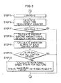
- the controlling device 24 conducts procedures shown by flowcharts in Figures 2 to 4 in each predetermined cycle time. First, there will be described operation of a case that for the operator to suspend the working operation when the hydraulic working machine is in the normal operation, all the control levers 14 to 19 are shifted to their respective neutral positions and maintained therein.
- the processor 27 of the controlling device 24 reads a designated rotational speed SLT ⁇ R of the engine 1 designated by the throttle lever 21 (STEP 1) based on the signal sent from the throttle lever 21 to the signal input portion 25. Then, the processor 27 judges whether or not all the control levers 14 to 19 are in their respective neutral positions based on the signals sent from each of the control levers 14 to 19 to the signal input portion 25 (STEP 2).
- the processor 27 judges whether or not the value of flag LVR ⁇ FG is "0" (STEP 3).
- the value of the flag LVR ⁇ FG is set to "1" via STEP 5 which will be described later.
- the value in the normal operation or the initial value of the flag LVR ⁇ FG is "0". Accordingly, the value of the flag LVR ⁇ FG at this time is "0" (YES in STEP 3).
- the processor 27 calculates a shifting speed LVR ⁇ SP of the control lever which is lastly shifted to its neutral position among the control levers 14 to 19 (STEP 4).
- the storage portion 26 stores data on the shifting amounts of each of control levers 14 to 19 in time sequence in the order from the present to the past.
- the shifting amounts are obtained based on the signals sent from each of control levers 14 to 19 in each cycle time.
- the processor 27 Based on the stored data, the processor 27 recognizes which control lever is lastly shifted to its neutral position. Then, the processor 27 obtains a shifting speed LVR ⁇ SP of the last control lever based on the above-mentioned shifting amount data in the time sequence (more specifically, an average value of shifting speeds in a plurality of cycle times until the control lever reaching the neutral position).
- the shifting speed LVR ⁇ SP may be an average value of shifting speeds of shifted control levers among the control levers 14 to 19.
- the processor 27 Upon obtaining the shifting speed LVR ⁇ SP, the processor 27 sets the value of the flag VLR - FG to "1" (STEP 5). As far as the control levers 14 to 19 are maintained in their respective neutral positions in the next cycle time and afterward, that is, as far as the result of judgment in STEP 2 is "YES", the value of the flag LVR ⁇ FG is kept at "1". Accordingly, the result of judgment in STEP 3 becomes "NO" in the next cycle time and afterward. In this case, the procedures in STEPs 4 and 5 are omitted and the following procedures are performed.
- the processor 27 judges whether or not the value of flag DES ⁇ FG is "0" or not (STEP 6).
- the flag DES ⁇ FG is used to judge whether or not the engine 1 is controlled to run at a predetermined low rotational speed (e.g., at a speed of 1050 rpm or less, hereinafter, this low rotational speed is referred to as "DECEL rotational speed") to reduce the fuel consumption when the working operation is suspended.
- the value of the normal operation or the initial value is "0".
- the flag DES ⁇ FG is set to "1" via STEP 13 which will be described later. In this case, the value of the flag DES ⁇ FG is "0", and the processor 27 judges whether or not the shifting speed LVR ⁇ SP obtained in STEP 4 is greater than the predetermined speed S 1 (STEP 7).
- the shifting speed of the control levers 14 to 19 to the neutral positions is relatively high.
- the shifting speed LVR ⁇ SP is equal to or higher than the predetermined speed S 1 (LVR - SP ⁇ S 1 :YES in STEP 7), and the processor 27 increases the value of the first counter Ta for time measurement by "1" (STEP 8).
- the value of the first counter Ta is increased by "1" in STEP 8 in each cycle time as far as all the control levers 14 to 19 are maintained in their respective neutral positions in the next cycle time and afterward.
- the value of the first counter Ta is an indicator of the elapsed time from the point where all the control levers 14 to 19 are shifted to their respective neutral positions.
- the time is measured by the same manner as that conducted in the case where the shifting speed LVR ⁇ SP is equal to or higher than Si (LVR - SP ⁇ S 1 ), which will be described later.
- the processor 27 judges whether or not the value of the first counter Ta is equal to or larger than the predetermined first delay time T1 (STEP 9).
- the first delay time T1 is a delay time for the high shifting speed which is determined in correspondence to the case of LVR ⁇ SP ⁇ S 1 in STEP 7, that is, in the case where the shifting speed of the control lever lastly set to its neutral position among the control levers 14 to 19 is the high shifting speed equal to or higher than the predetermined speed Si.
- the first delay time T1 is set in a relatively short time (e.g., 4 seconds). However, immediately after all the control levers 14 to 19 are shifted to their respective neutral positions, the value of the first counter Ta is smaller than the value of the first delay time T1 (Ta ⁇ T1: NO in STEP 9).
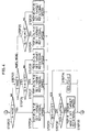
- the processor 27 conducts procedures shown by the flowchart in Figure 4. More specifically, the processor 27 sets a target rotational speed TGT ⁇ R of the engine 1 by the following steps in accordance with an operation mode selected by the mode changing switch 20.
- the target rotational speed TGT ⁇ R is set to the designated rotational speed SLT ⁇ R of up to the upper limit rotational speed which corresponds to the operation mode selected by the mode changing switch 20.
- the processor 27 judges whether or not the value of the flag DES ⁇ FG is "0" (STEP 31). At this point, the value of the flag DES ⁇ FG is still "0" (YES in step 31), and therefore, the procedure is returned to STEP 14 in Figure 2, and the procedure of this cycle time is completed.
- the processor 27 designates the target rotational speed TGT ⁇ R which is determined in any one of STEPs 26 to 30 shown in Figure 4 to the throttle driving portion 29.
- the throttle driving portion 29 drives the throttle motor 23 and controls the engine 1 to run at the target rotational speed TGT ⁇ R.
- the engine 1 is basically controlled to run at the rotational speed SLT ⁇ R designated by the throttle lever 21.
- the upper limit of the target rotational speed TGT ⁇ R is not limited to a specific value.
- the upper limit of the rotational speed of the engine 1 is mechanically limited to a predetermined value (e.g., 2350rpm) by unillustrated throttle stopper provided to the engine 1.
- the target rotational speed TGT R is set to the DECEL rotational speed DES R (STEP 12B).
- the target rotational speed TGT ⁇ R is set to the designated rotational speed SLT ⁇ R (STEP 12A).
- the designated rotational speed SLT ⁇ R is set to be higher than the DECEL rotational speed DES ⁇ R.
- this controlling device when the designated rotational speed SLT ⁇ R is equal to or higher than the DECEL rotational speed DES ⁇ R, the engine 1 is automatically controlled and maintained to run at the DECEL rotational speed DES ⁇ R after the elapse of the first delay time T1 from the point where all the control levers 14 to 19 are shifted to their respective neutral positions. This allows the engine 1 to run at a reduced fuel.
- the processor 27 increases the value of the second counter Tb for time measurement by "1" (STEP 10).
- the value of the second counter Tb is an indicator of elapsed time from the point where all the control levers 14 to 19 are shifted to their respective neutral positions, and is increased by "1" in STEP 10 in each cycle time as far as the control levers 14 to 19 are maintained in their neutral positions.
- the second delay time T2 is a delay time for low shifting speed determined in the case of LVR ⁇ SP ⁇ S 1 (NO in STEP 7), that is, the last control lever among the shifted control levers 14 to 19 is shifted to its neutral position at the speed lower than the predetermined speed S 1 .
- the second delay time T2 is set to relatively longer time than the first delay time T1 (e.g., 20 seconds).
- the engine 1 is basically controlled to run at the designated rotational speed SLT ⁇ R through the procedures shown in Figure 4.
- the engine 1 is controlled to run at the DECEL rotational speed DES ⁇ R via the procedure in Step 12.
- the engine 1 is controlled to run at the designated rotational speed SLT ⁇ R even after the elapse of the second delay time T2.
- the rotational speed of the engine 1 is automatically decreased to the DECEL rotational speed DES ⁇ R after the elapse of the first delay time T or the second delay time T2 from the point where the last control lever is shifted to its neutral position.
- the shifting speed LVR ⁇ SP of the last control lever shifted to its neutral position is a high shifting speed equal to or higher than the predetermined speed S 1 .
- the first delay time T1 is adopted.
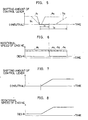
- one of the control levers 14 to 19 is shifted from its neutral position to its working position before the elapse of the first delay time T1, as shown by a dashed line a3 in Figure 5.
- the processor 27 resets the value of the flag LVR ⁇ FC to "0" (STEP 15), and also resets the value of the first counter Ta and the second counter Tb for time measurement (STEP 16). Then, the processor 27 judges whether or not the value of the flag DES ⁇ FG is "0" (STEP 17). In this case, as described above, one of the control levers 14 to 19 is shifted before the elapse of the first delay time T1, the engine 1 is still not controlled to run at the DECEL rotational speed DES ⁇ R (or the designated rotational speed SLT ⁇ R in the case of SLT ⁇ R ⁇ DES ⁇ R). Therefore, the value of the flag DES ⁇ FG is 0 (YES in STEP 17).
- the processor 27 conducts the procedures of STEPs 22 to 31 shown in Figure 4, and then, conducts the procedure of STEP 14 shown in Figure 2.
- the engine 1 is continuously controlled to run at the designated rotational speed SLT ⁇ R designated by the throttle lever 21 (or the upper limit rotational speed corresponding to each operation mode when the designated rotational speed SLT ⁇ R is higher than this upper limit rotational speed.).
- the processor 27 starts the procedures shown in Figure 3. Then, the processor 27 repeats the same procedure as that conducted in the case where one of the control levers 14 to 19 is shifted within the first delay time T1.
- the engine 1 is continuously controlled to run at the designated rotational speed SLT ⁇ R designated by the throttle lever 21 (or the upper limit rotational speed corresponding to each operation mode when the designated rotational speed SLT ⁇ R is higher than the upper limit rotational speed).
- the processor 27 resets the flag LVR ⁇ FG, the first counter Ta, and the second counter Tb (STEPs 15 and 16), and then judges whether or not the value of flag DES ⁇ SG is "0".
- the processor 27 obtains the present shifting amount LVR ⁇ S of each of the control levers 14 to 19 based on the signals sent from each of the control levers 14 to 19 (STEP 18).
- the processor 27 obtains a variation ⁇ LVR ⁇ S of the shifting amount of each of control levers 14 to 19 changed from the preceding cycle time. Then, the processor 27 judges whether or not the variation ⁇ LVR ⁇ S is "0" or less, in other words, whether or not all the control levels 14 to 19 are now being shifted toward their respective neutral positions (STEP 20).
- the processor 27 obtains a rotational speed RTN ⁇ R for restoring the rotational speed of the engine 1 from the DECEL rotational speed DES ⁇ S to the rotational speed for the normal operation (STEP 21) using the following Equation (1):
- R T N ⁇ R max ( L V R ⁇ S ) L V R ⁇ S M ⁇ ( H ⁇ R ⁇ D E S ⁇ R ) + D E S ⁇ R
- max (LVR ⁇ S) denotes the maximum value of the shifting amount of each of the control levers 14 to 19 obtained in STEP 18
- LVR ⁇ SM denotes the predetermined allowable maximum shifting amount corresponding to the maximum value of the shifting amount LVR ⁇ S
- H ⁇ R denotes the maximum upper limit rotational speed of the engine 1 (e.g., 2350rpm, this value is equal to the upper limit rotational speed of the engine 1 in the H mode operation).
- designated restoring rotational speed RTN ⁇ R corresponds to the present shifting amount of the control lever which is most greatly shifted in restarting the operation.
- the shifting amount of the control lever which is most greatly shifted is the half of the allowable maximum shifting amount LVR ⁇ SM
- the designated restoring rotational speed RTN ⁇ R is at an intermediate value between the maximum upper limit rotational speed H ⁇ R and the DECEL rotational speed DES ⁇ R [(H ⁇ R + DES ⁇ R)/2] .
- the shifting amount of the control lever which is most greatly shifted is the allowable maximum shifting amount LVR ⁇ SM
- the designated restoring rotational speed RTN ⁇ R is at the maximum upper limit rotational speed H ⁇ R.
- the processor 27 Upon obtaining the designated restoring rotational speed RTN ⁇ R, the processor 27 performs the procedures of STEPs 22 to 30 shown in Figure 4. Then, as described above, the processor 27 sets the target rotational speed TGT ⁇ R of the engine 1 to the rotational speed SLT ⁇ R designated by the throttle lever 21 (or the upper limit rotational speed when the SLT ⁇ R is larger than the upper limit rotational speed corresponding to each operation mode).
- the processor 27 judges whether or not the value of the flag DES ⁇ FG is "0" (STEP 31). Immediately after the operation is restarted, the value of the flag DES ⁇ FG is "1". Therefore, the processor 27 judges whether or not the target rotational speed TGT - R set in the STEPs 22 to 30 is equal to or higher than that of the designated restoring rotational speed RTN - R (STEP 32). In the case of TGT ⁇ R ⁇ RTN - R (YES in STEP 32), the processor 27 sets the target rotational speed TGT ⁇ R to the designated restoring rotational speed RTN ⁇ R (STEP 33).
- the processor 27 keeps the value of the target rotational speed TGT ⁇ R as it is , and resets the value of the flag DES - FG to "0" (STEP 34). After that, the processor 27 designates the target rotational speed TGT ⁇ R to the throttle driving portion 29 in STEP 14, and this cycle time is completed. In this case, when the value of the flag DES ⁇ FG is reset to "0" in STEP 34, the procedures of STEPs 32 and 33 are not conducted, because the result of judgment in STEP 31 is YES in the next cycle time and afterward.
- the target rotational speed TGT ⁇ R is set to the designated restoring rotational speed RTN ⁇ N until the designated restoring rotational speed RTN ⁇ R reaches the designated rotational speed SLT ⁇ R (or the upper limit rotational speed corresponding to each operation mode when the SLT - R is larger than this upper limit rotational speed) (YES in STEP 32).
- the engine 1 is controlled to run at the rotational speed which is increased from the DECEL rotational speed DES ⁇ R in accordance with an increase in the shifting amount of the control lever.
- the target rotational speed TGT ⁇ R is set to the designated rotational speed SLT ⁇ R or the upper limit rotational speed corresponding to each operation mode. In this way, the engine 1 is controlled to run at the rotational speed for the normal operation.
- the rotational speed of the engine 1 when the rotational speed of the engine 1 is restored from the DECEL rotational speed DES ⁇ R to the rotational speed for the normal operation, such as the rotational speed SLT ⁇ R designated by the throttle lever 21, to restart the operation, the rotational speed of the engine 1 is increased from the DECEL rotational speed DES ⁇ R to the rotational speed for the normal operation in accordance with an increase in the shifting amount of the shifted control lever to restart the operation.
- the engine 1 can be smoothly restored to its normal operation mode in accordance with the operator's intention.
- the processor 27 omits the procedure of STEP 21 for newly obtaining the designated restoring rotational speed RTN ⁇ R, and sets the target rotational speed TGT ⁇ R to the previously obtained designated restoring rotational speed RTN ⁇ R via STEP 33 in Figure 4.
- the engine 1 is maintained to run at the present rotational speed. In other words, the engine 1 is controlled to run at the rotational speed adequate for the operation without being increased to excessively high value.
- the engine 1 can be accurately and automatically controlled to run at the rotational speed required by the operator by shifting the control levers 14 to 19.
- the rotational speed of the engine when the operation is suspended, the rotational speed of the engine is automatically and accurately changed from the designated rotational speed to the low rotational speed to save the fuel consumption without requiring any specific manipulation by the operator.
- the rotational speed of the engine comes into the low rotational speed against the operator's intention.
- the rotational speed of the engine can be smoothly restored to the designated rotational speed.
Landscapes
- Engineering & Computer Science (AREA)
- General Engineering & Computer Science (AREA)
- Mining & Mineral Resources (AREA)
- Structural Engineering (AREA)
- Civil Engineering (AREA)
- Mechanical Engineering (AREA)
- Chemical & Material Sciences (AREA)
- Combustion & Propulsion (AREA)
- Computer Hardware Design (AREA)
- Physics & Mathematics (AREA)
- Fluid Mechanics (AREA)
- Control Of Vehicle Engines Or Engines For Specific Uses (AREA)
- Operation Control Of Excavators (AREA)
- Fluid-Pressure Circuits (AREA)
Claims (6)
- Steuervorrichtung für ein Steuern der Drehzahl eines Verbrennungsmotors einer hydraulischen Arbeitsmaschine, die mit Folgendem versehen ist:einer hydraulischen Pumpe, die durch einen Verbrennungsmotor angetrieben wird;einer Vielzahl von Betätigungselementen, die durch Öl betrieben werden, das unter Druck von der hydraulischen Pumpe zugeführt wird;einer Vielzahl von Betätigungsbetriebselementen für ein jeweiliges Betreiben der Vielzahl von Betätigungselementen; undeiner Drehzahlbestimmungseinrichtung für ein Bestimmen einer Drehzahl des Verbrennungsmotors,wobei die Steuervorrichtung folgendes aufweist:einer Verzögerungszeiteinstelleinrichtung für ein Einstellen einer Verzögerungszeit, wenn alle die Betätigungsbetriebselemente zu ihren jeweiligen Ruhepositionen geschaltet werden, in einem Zustand, bei dem der Verbrennungsmotor bei einer Drehzahl ist, die durch die Drehzahlbestimmungseinrichtung bestimmt wird; undeine Drehzahlsteuereinrichtung für ein Messen einer vergangenen Zeit, während der Verbrennungsmotor gesteuert wird, um bei der bestimmten Drehzahl zu laufen, wenn alle die Betätigungsbetriebselemente zu ihren jeweiligen Ruhepositionen geschaltet werden, und für ein Steuern des Verbrennungsmotors, um bei einer vorbestimmten niedrigen Drehzahl zu laufen, um Kraftstoff einzusparen, in einem Fall, dass die vergangene Zeit die eingestellte Verzögerungszeit in einem Zustand erreicht, bei dem alle die Betätigungsbetriebselemente in den Ruhepositionen verbleibend gehalten werden, wohingegen die Messung der vergangenen Zeit zurückgestellt wird und der Verbrennungsmotor gesteuert wird, um bei der bestimmten Drehzahl zu laufen, in einem Fall, bei dem wenigstens eines der Betätigungsbetriebselemente von der Ruheposition zu einer Arbeitsposition geschaltet wird, bevor die vergangene Zeit die Verzögerungszeit erreicht,dadurch gekennzeichnet, dassdie Verzögerungszeiteinstelleinrichtung die Verzögerungszeit gemäß einer Schaltgeschwindigkeit von wenigstens einem von der Vielzahl von Betätigungsbetriebselementen zu einer Ruheposition von diesem einstellt,wobei die Verzögerungszeiteinstelleinrichtung eine längere Zeit in einem Fall einer niedrigen Schaltgeschwindigkeit einstellt, in dem die Schaltgeschwindigkeit niedriger ist als ein vorbestimmter Wert, als in einem Fall einer hohen Schaltgeschwindigkeit, in dem die Schaltgeschwindigkeit höher ist als der vorbestimmte Wert.
- Steuervorrichtung zum Steuern der Drehzahl eines Verbrennungsmotors einer hydraulischen Arbeitsmaschine gemäß Anspruch 1, wobei die Verzögerungszeiteinstelleinrichtung eine Verzögerungszeit gemäß einer Schaltgeschwindigkeit eines Betätigungsbetriebselements einstellt, das zuletzt zu seiner Ruheposition geschalten worden ist unter der Vielzahl von Betätigungsbetriebselementen.
- Steuervorrichtung für ein Steuern der Drehzahl eines Verbrennungsmotors einer hydraulischen Arbeitsmaschine gemäß Anspruch 1 oder 2, wobei die Drehzahlsteuereinrichtung die Drehzahl des Verbrennungsmotors von der niedrigen Drehzahl zu der bestimmten Drehzahl gemäß einer Erhöhung des Schaltumfangs des Betätigungsbetriebselements erhöht, wenn wenigstens eines der Betätigungsbetriebselemente von seiner Ruheposition zu seiner maximalen Arbeitsposition geschalten wird, nachdem der Motor gesteuert worden ist, um bei der niedrigen Drehzahl zu laufen, und die bestimmte Drehzahl aufrecht erhält, nachdem die Drehzahl des Verbrennungsmotors die bestimmte Drehzahl erreicht.
- Steuervorrichtung für ein Steuern der Drehzahl eines Verbrennungsmotors einer hydraulischen Arbeitsmaschine gemäß Anspruch 3, wobei die Drehzahlsteuereinrichtung die Drehzahl des Verbrennungsmotors gemäß einer Erhöhung des Schaltumfangs eines Betätigungsbetriebselements erhöht, das am stärksten unter den geschalteten Betriebselementen geschaltet wird, wenn eine Vielzahl der Betätigungsbetriebselemente von ihren jeweiligen Ruhepositionen zu ihren maximalen Arbeitspositionen geschaltet wird.
- Steuervorrichtung für ein Steuern der Drehzahl eines Verbrennungsmotors einer hydraulischen Arbeitsmaschine gemäß Anspruch 3 oder 4, wobei die Drehzahlsteuereinrichtung die Erhöhung der Drehzahl des Verbrennungsmotors stoppt und die vorliegende Drehzahl aufrechterhält, wenn alle die geschalteten Betriebsbetätigungselemente zu ihren jeweiligen Ruhepositionen zurückgestellt werden, in einem Zustand, bei der die Drehzahl des Verbrennungsmotors erhöht wird.
- Steuervorrichtung für ein Steuern der Drehzahl eines Verbrennungsmotors einer hydraulischen Arbeitsmaschine gemäß Anspruch 5, wobei, in dem Fall, bei dem alle die geschalteten Betätigungsbetriebselemente zu ihren jeweiligen Ruhepositionen zurückgestellt werden und bei diesen aufrechterhalten werden, in einem Zustand, bei der die Rotationsgeschwindigkeit des Verbrennungsmotors erhöht wird, die Drehzahlsteuereinrichtung den Verbrennungsmotor steuert, um bei der niedrigen Drehzahl zu laufen, nachdem die vergangene Zeit eine Verzögerungszeit erreicht, die gemäß einer Schaltgeschwindigkeit von wenigstens einem von den geschalteten Betätigungsbetriebselementen eingestellt wird, das zu seiner Ruheposition zurückgestellt wird, und die Drehzahlsteuereinrichtung die Drehzahl des Verbrennungsmotors zu der bestimmten Drehzahl gemäß einer Erhöhung des Schaltumgangs des Betätigungsbetriebselements erhöht, wenn wenigstens eines der Betätigungsbetriebselemente von seiner Ruheposition zu seiner maximalen Arbeitsposition geschalten wird, bevor die vergangene Zeit die Verzögerungszeit erreicht.
Applications Claiming Priority (3)
| Application Number | Priority Date | Filing Date | Title |
|---|---|---|---|
| JP23851695A JP3520301B2 (ja) | 1995-09-18 | 1995-09-18 | 油圧作業機のエンジン回転数の制御方法 |
| JP238516/95 | 1995-09-18 | ||
| PCT/JP1996/002636 WO1997011265A1 (en) | 1995-09-18 | 1996-09-13 | Device for controlling the rotation speed of an engine for a hydraulic working machine |
Publications (3)
| Publication Number | Publication Date |
|---|---|
| EP0791737A1 EP0791737A1 (de) | 1997-08-27 |
| EP0791737A4 EP0791737A4 (de) | 2003-01-22 |
| EP0791737B1 true EP0791737B1 (de) | 2006-06-21 |
Family
ID=17031422
Family Applications (1)
| Application Number | Title | Priority Date | Filing Date |
|---|---|---|---|
| EP96930401A Expired - Lifetime EP0791737B1 (de) | 1995-09-18 | 1996-09-13 | Vorrichtung zur steuerung der drehzahl eines motors einer hydraulischen baumaschine |
Country Status (7)
| Country | Link |
|---|---|
| US (1) | US5967758A (de) |
| EP (1) | EP0791737B1 (de) |
| JP (1) | JP3520301B2 (de) |
| KR (1) | KR100256897B1 (de) |
| CN (1) | CN1068093C (de) |
| DE (1) | DE69636274T2 (de) |
| WO (1) | WO1997011265A1 (de) |
Families Citing this family (11)
| Publication number | Priority date | Publication date | Assignee | Title |
|---|---|---|---|---|
| GB9809627D0 (en) * | 1998-05-07 | 1998-07-01 | Specialist Vehicles Limited | Refuse vehicle engine control |
| US6113193A (en) * | 1999-02-02 | 2000-09-05 | Caterpillar Inc. | Apparatus and method for automatically reducing engine exhaust noise |
| JP3390707B2 (ja) * | 1999-10-19 | 2003-03-31 | 住友建機製造株式会社 | 建設機械の制御装置 |
| DE10150467A1 (de) * | 2001-10-16 | 2003-04-17 | Putzmeister Ag | Dickstoffpumpe mit Fördermengenregelung |
| US6694240B1 (en) * | 2002-08-29 | 2004-02-17 | Caterpillar Inc | Control system for and method of operating a work machine |
| US8190334B2 (en) * | 2007-02-21 | 2012-05-29 | Kobelco Construction Machinery Co., Ltd. | Rotation control device and working machine therewith |
| KR101685206B1 (ko) * | 2010-12-21 | 2016-12-12 | 두산인프라코어 주식회사 | 건설장비의 로우아이들 제어 시스템 및 그 자동 제어방법 |
| JP6415839B2 (ja) * | 2014-03-31 | 2018-10-31 | 住友重機械工業株式会社 | ショベル |
| US9759147B2 (en) | 2014-08-29 | 2017-09-12 | Cnh Industrial America Llc | Idle return system and method for an off highway vehicle |
| JP6913423B2 (ja) * | 2015-09-08 | 2021-08-04 | 株式会社クボタ | 作業機の油圧システム |
| TWI660114B (zh) * | 2018-11-23 | 2019-05-21 | 劉文偉 | 並接式增加工具車油壓動力的發動機 |
Family Cites Families (12)
| Publication number | Priority date | Publication date | Assignee | Title |
|---|---|---|---|---|
| DE7927688U1 (de) * | 1979-09-28 | 1980-08-14 | Achterholt, Rainer, 8963 Waltenhofen | Kraftfahrzeug mit elektronischer motorabschaltvorrichtung |
| JPS6038561B2 (ja) * | 1980-04-03 | 1985-09-02 | 日立建機株式会社 | 油圧式建設機械のエンジン回転数の制御方法 |
| US4549400A (en) | 1982-04-19 | 1985-10-29 | King Alex C | Electro-hydraulic engine throttle control |
| DE3307596C2 (de) * | 1983-01-04 | 1991-01-03 | Liebherr-Hydraulikbagger Gmbh, 7951 Kirchdorf | Vorrichtung zur Steuerung der Drehzahl eines Dieselmotors eines Hydraulikbaggers oder dergleichen |
| JPS6038561A (ja) * | 1983-08-11 | 1985-02-28 | ダイキン工業株式会社 | 複合ヒ−トポンプ加熱装置 |
| JPS61142338A (ja) * | 1984-12-13 | 1986-06-30 | Komatsu Ltd | オ−トデセル装置付きエンジンの制御方法 |
| JPS62142834A (ja) * | 1985-12-17 | 1987-06-26 | Komatsu Ltd | クレ−ンのエンジン制御装置 |
| JPS62191638A (ja) * | 1986-02-19 | 1987-08-22 | Komatsu Ltd | オ−トデセル装置付きエンジンの制御方法 |
| US4838755A (en) | 1987-02-19 | 1989-06-13 | Deere & Company | Automatic engine control for an excavator |
| JPH02125035A (ja) * | 1988-10-31 | 1990-05-14 | Hitachi Constr Mach Co Ltd | 油圧式建設機械の原動機回転数制御装置 |
| JPH02167935A (ja) * | 1988-12-20 | 1990-06-28 | Hitachi Constr Mach Co Ltd | 油圧式建設機械の原動機回転数制御装置 |
| JP3115887B2 (ja) * | 1990-09-28 | 2000-12-11 | 株式会社小松製作所 | クローズドセンタ・ロードセンシングシステムにおけるポンプの吐出容積の可変回路 |
-
1995
- 1995-09-18 JP JP23851695A patent/JP3520301B2/ja not_active Expired - Fee Related
-
1996
- 1996-09-13 EP EP96930401A patent/EP0791737B1/de not_active Expired - Lifetime
- 1996-09-13 WO PCT/JP1996/002636 patent/WO1997011265A1/ja not_active Ceased
- 1996-09-13 DE DE69636274T patent/DE69636274T2/de not_active Expired - Fee Related
- 1996-09-13 KR KR1019970703107A patent/KR100256897B1/ko not_active Expired - Fee Related
- 1996-09-13 US US08/836,471 patent/US5967758A/en not_active Expired - Fee Related
- 1996-09-13 CN CN96191096A patent/CN1068093C/zh not_active Expired - Fee Related
Also Published As
| Publication number | Publication date |
|---|---|
| DE69636274D1 (de) | 2006-08-03 |
| EP0791737A1 (de) | 1997-08-27 |
| KR100256897B1 (ko) | 2000-05-15 |
| CN1068093C (zh) | 2001-07-04 |
| JPH0979206A (ja) | 1997-03-25 |
| DE69636274T2 (de) | 2006-11-09 |
| WO1997011265A1 (en) | 1997-03-27 |
| US5967758A (en) | 1999-10-19 |
| EP0791737A4 (de) | 2003-01-22 |
| JP3520301B2 (ja) | 2004-04-19 |
| KR970707370A (ko) | 1997-12-01 |
| CN1165548A (zh) | 1997-11-19 |
Similar Documents
| Publication | Publication Date | Title |
|---|---|---|
| EP1544440B1 (de) | Antriebsaggregatsteuerung einer baumaschine. | |
| EP0522171B1 (de) | Hydraulisches steuerungssystem für hydraulische erdbaumaschine | |
| US5941155A (en) | Hydraulic motor control system | |
| EP1790859B1 (de) | Hydraulische Steuerung für eine Bearbeitungsmaschine | |
| US5967758A (en) | Controlling device for controlling rotational speed of engine of hydraulic working machine | |
| EP0551513A1 (de) | Hydraulisches betätigungssystem für baumaschinen | |
| JPH07119506A (ja) | 油圧建設機械の原動機回転数制御装置 | |
| JP2000204600A (ja) | 油圧ショベルの制御装置 | |
| CN110091712B (zh) | 工程机械的行驶控制装置及行驶控制方法 | |
| JPH10183689A (ja) | 油圧制御装置 | |
| JPH09273183A (ja) | 油圧式建設機械のエンジン回転数制御装置 | |
| EP0774546B1 (de) | Verfahren und Vorrichtung zum Regeln der Motordrehzahl einer hydraulischen Baumaschine | |
| JP2690353B2 (ja) | ロードセンシングシステムを用いた油圧回路のメイクアップ装置 | |
| JP3706095B2 (ja) | 建設機械の制御装置 | |
| JPH08199631A (ja) | 建設機械の油圧制御装置 | |
| JPH09195947A (ja) | 建設機械の油圧駆動装置 | |
| GB2394316A (en) | Control unit for a construction machine | |
| JP3308073B2 (ja) | 油圧建設機械の原動機回転数制御装置 | |
| JP3241062B2 (ja) | 作業機のポンプ流量制御装置 | |
| JP3816503B2 (ja) | 建設機械の制御装置 | |
| KR0171390B1 (ko) | 유압건설기계의 엔진 자동장치 제어방법 | |
| JP2981339B2 (ja) | 建設機械用アクチュエーター油圧源ポンプ駆動エンジンの制御方法 | |
| JPH04258418A (ja) | 油圧建設機械の油圧制御装置 | |
| JPH11270514A (ja) | 油圧制御装置 | |
| KR100188884B1 (ko) | 유압식 건설기계의 엔진회전수 제어장치 |
Legal Events
| Date | Code | Title | Description |
|---|---|---|---|
| PUAI | Public reference made under article 153(3) epc to a published international application that has entered the european phase |
Free format text: ORIGINAL CODE: 0009012 |
|
| 17P | Request for examination filed |
Effective date: 19970530 |
|
| AK | Designated contracting states |
Kind code of ref document: A1 Designated state(s): DE FR GB IT |
|
| RAP1 | Party data changed (applicant data changed or rights of an application transferred) |
Owner name: KOBELCO CONSTRUCTION MACHINERY CO., LTD. |
|
| A4 | Supplementary search report drawn up and despatched |
Effective date: 20021205 |
|
| AK | Designated contracting states |
Kind code of ref document: A4 Designated state(s): DE FR GB IT |
|
| RIC1 | Information provided on ipc code assigned before grant |
Free format text: 7F 02D 29/04 A, 7F 02D 41/04 B, 7E 02F 9/22 B, 7F 04B 49/06 B, 7E 02F 9/20 B |
|
| GRAP | Despatch of communication of intention to grant a patent |
Free format text: ORIGINAL CODE: EPIDOSNIGR1 |
|
| GRAS | Grant fee paid |
Free format text: ORIGINAL CODE: EPIDOSNIGR3 |
|
| GRAA | (expected) grant |
Free format text: ORIGINAL CODE: 0009210 |
|
| AK | Designated contracting states |
Kind code of ref document: B1 Designated state(s): DE FR GB IT |
|
| REG | Reference to a national code |
Ref country code: GB Ref legal event code: FG4D |
|
| REF | Corresponds to: |
Ref document number: 69636274 Country of ref document: DE Date of ref document: 20060803 Kind code of ref document: P |
|
| PGFP | Annual fee paid to national office [announced via postgrant information from national office to epo] |
Ref country code: GB Payment date: 20060911 Year of fee payment: 11 |
|
| PGFP | Annual fee paid to national office [announced via postgrant information from national office to epo] |
Ref country code: FR Payment date: 20060919 Year of fee payment: 11 |
|
| PGFP | Annual fee paid to national office [announced via postgrant information from national office to epo] |
Ref country code: IT Payment date: 20060930 Year of fee payment: 11 |
|
| PGFP | Annual fee paid to national office [announced via postgrant information from national office to epo] |
Ref country code: DE Payment date: 20061031 Year of fee payment: 11 |
|
| ET | Fr: translation filed | ||
| PLBE | No opposition filed within time limit |
Free format text: ORIGINAL CODE: 0009261 |
|
| STAA | Information on the status of an ep patent application or granted ep patent |
Free format text: STATUS: NO OPPOSITION FILED WITHIN TIME LIMIT |
|
| 26N | No opposition filed |
Effective date: 20070322 |
|
| GBPC | Gb: european patent ceased through non-payment of renewal fee |
Effective date: 20070913 |
|
| PG25 | Lapsed in a contracting state [announced via postgrant information from national office to epo] |
Ref country code: DE Free format text: LAPSE BECAUSE OF NON-PAYMENT OF DUE FEES Effective date: 20080401 |
|
| REG | Reference to a national code |
Ref country code: FR Ref legal event code: ST Effective date: 20080531 |
|
| PG25 | Lapsed in a contracting state [announced via postgrant information from national office to epo] |
Ref country code: FR Free format text: LAPSE BECAUSE OF NON-PAYMENT OF DUE FEES Effective date: 20071001 |
|
| PG25 | Lapsed in a contracting state [announced via postgrant information from national office to epo] |
Ref country code: GB Free format text: LAPSE BECAUSE OF NON-PAYMENT OF DUE FEES Effective date: 20070913 |
|
| PG25 | Lapsed in a contracting state [announced via postgrant information from national office to epo] |
Ref country code: IT Free format text: LAPSE BECAUSE OF NON-PAYMENT OF DUE FEES Effective date: 20070913 |