EP0788829B1 - Catalyseur et méthode pour la réduction catalytique d'oxydes d'azote - Google Patents
Catalyseur et méthode pour la réduction catalytique d'oxydes d'azote Download PDFInfo
- Publication number
- EP0788829B1 EP0788829B1 EP97300816A EP97300816A EP0788829B1 EP 0788829 B1 EP0788829 B1 EP 0788829B1 EP 97300816 A EP97300816 A EP 97300816A EP 97300816 A EP97300816 A EP 97300816A EP 0788829 B1 EP0788829 B1 EP 0788829B1
- Authority
- EP
- European Patent Office
- Prior art keywords
- catalyst
- silver
- alumina
- amount
- weight
- Prior art date
- Legal status (The legal status is an assumption and is not a legal conclusion. Google has not performed a legal analysis and makes no representation as to the accuracy of the status listed.)
- Expired - Lifetime
Links
Images


Classifications
-
- B—PERFORMING OPERATIONS; TRANSPORTING
- B01—PHYSICAL OR CHEMICAL PROCESSES OR APPARATUS IN GENERAL
- B01J—CHEMICAL OR PHYSICAL PROCESSES, e.g. CATALYSIS OR COLLOID CHEMISTRY; THEIR RELEVANT APPARATUS
- B01J23/00—Catalysts comprising metals or metal oxides or hydroxides, not provided for in group B01J21/00
- B01J23/38—Catalysts comprising metals or metal oxides or hydroxides, not provided for in group B01J21/00 of noble metals
- B01J23/54—Catalysts comprising metals or metal oxides or hydroxides, not provided for in group B01J21/00 of noble metals combined with metals, oxides or hydroxides provided for in groups B01J23/02 - B01J23/36
- B01J23/66—Silver or gold
- B01J23/68—Silver or gold with arsenic, antimony, bismuth, vanadium, niobium, tantalum, polonium, chromium, molybdenum, tungsten, manganese, technetium or rhenium
-
- B—PERFORMING OPERATIONS; TRANSPORTING
- B01—PHYSICAL OR CHEMICAL PROCESSES OR APPARATUS IN GENERAL
- B01D—SEPARATION
- B01D53/00—Separation of gases or vapours; Recovering vapours of volatile solvents from gases; Chemical or biological purification of waste gases, e.g. engine exhaust gases, smoke, fumes, flue gases, aerosols
- B01D53/34—Chemical or biological purification of waste gases
- B01D53/92—Chemical or biological purification of waste gases of engine exhaust gases
- B01D53/94—Chemical or biological purification of waste gases of engine exhaust gases by catalytic processes
- B01D53/9404—Removing only nitrogen compounds
- B01D53/9409—Nitrogen oxides
- B01D53/9413—Processes characterised by a specific catalyst
- B01D53/9418—Processes characterised by a specific catalyst for removing nitrogen oxides by selective catalytic reduction [SCR] using a reducing agent in a lean exhaust gas
-
- B—PERFORMING OPERATIONS; TRANSPORTING
- B01—PHYSICAL OR CHEMICAL PROCESSES OR APPARATUS IN GENERAL
- B01J—CHEMICAL OR PHYSICAL PROCESSES, e.g. CATALYSIS OR COLLOID CHEMISTRY; THEIR RELEVANT APPARATUS
- B01J23/00—Catalysts comprising metals or metal oxides or hydroxides, not provided for in group B01J21/00
- B01J23/38—Catalysts comprising metals or metal oxides or hydroxides, not provided for in group B01J21/00 of noble metals
- B01J23/48—Silver or gold
- B01J23/50—Silver
-
- B—PERFORMING OPERATIONS; TRANSPORTING
- B01—PHYSICAL OR CHEMICAL PROCESSES OR APPARATUS IN GENERAL
- B01D—SEPARATION
- B01D2251/00—Reactants
- B01D2251/20—Reductants
- B01D2251/208—Hydrocarbons
-
- B—PERFORMING OPERATIONS; TRANSPORTING
- B01—PHYSICAL OR CHEMICAL PROCESSES OR APPARATUS IN GENERAL
- B01D—SEPARATION
- B01D2251/00—Reactants
- B01D2251/20—Reductants
- B01D2251/21—Organic compounds not provided for in groups B01D2251/206 or B01D2251/208
-
- B—PERFORMING OPERATIONS; TRANSPORTING
- B01—PHYSICAL OR CHEMICAL PROCESSES OR APPARATUS IN GENERAL
- B01D—SEPARATION
- B01D2255/00—Catalysts
- B01D2255/10—Noble metals or compounds thereof
- B01D2255/104—Silver
-
- B—PERFORMING OPERATIONS; TRANSPORTING
- B01—PHYSICAL OR CHEMICAL PROCESSES OR APPARATUS IN GENERAL
- B01D—SEPARATION
- B01D2255/00—Catalysts
- B01D2255/20—Metals or compounds thereof
- B01D2255/207—Transition metals
- B01D2255/20723—Vanadium
-
- B—PERFORMING OPERATIONS; TRANSPORTING
- B01—PHYSICAL OR CHEMICAL PROCESSES OR APPARATUS IN GENERAL
- B01D—SEPARATION
- B01D2255/00—Catalysts
- B01D2255/20—Metals or compounds thereof
- B01D2255/207—Transition metals
- B01D2255/2073—Manganese
-
- B—PERFORMING OPERATIONS; TRANSPORTING
- B01—PHYSICAL OR CHEMICAL PROCESSES OR APPARATUS IN GENERAL
- B01D—SEPARATION
- B01D2255/00—Catalysts
- B01D2255/20—Metals or compounds thereof
- B01D2255/207—Transition metals
- B01D2255/20753—Nickel
-
- B—PERFORMING OPERATIONS; TRANSPORTING
- B01—PHYSICAL OR CHEMICAL PROCESSES OR APPARATUS IN GENERAL
- B01D—SEPARATION
- B01D2255/00—Catalysts
- B01D2255/20—Metals or compounds thereof
- B01D2255/207—Transition metals
- B01D2255/20769—Molybdenum
-
- B—PERFORMING OPERATIONS; TRANSPORTING
- B01—PHYSICAL OR CHEMICAL PROCESSES OR APPARATUS IN GENERAL
- B01D—SEPARATION
- B01D2255/00—Catalysts
- B01D2255/20—Metals or compounds thereof
- B01D2255/207—Transition metals
- B01D2255/20776—Tungsten
Definitions
- This invention relates to a method for catalytic reduction of nitrogen oxides. More particularly, the invention relates to a method for catalytic reduction of nitrogen oxides using a hydrocarbon and/or an oxygen-containing organic compound as a reducing agent, suitable for reducing and removing harmful nitrogen oxides contained in exhaust or waste gases from factories or automobiles.
- Nitrogen oxides contained in exhaust gases have been removed by, for example, a method in which the nitrogen oxides are oxidized and then absorbed in an alkali or a method in which the nitrogen oxides are reduced to nitrogen by using ammonia, hydrogen, carbon monoxide or hydrocarbons as a reducing agent.
- the former method requires a means for handling the resulting alkaline waste liquid to prevent environmental pollution.
- the latter method when it uses ammonia as a reducing agent, involves the problem that ammonia reacts with sulfur oxides in the exhaust gases to form salts, resulting in a reduction in catalytic activity.
- the latter method uses hydrogen, carbon monoxide or hydrocarbons as a reducing agent, the reducing agent preferentially reacts with oxygen because the exhaust gas contains oxygen in a higher concentration than nitrogen oxides. This means that substantial reduction of nitrogen oxides requires a large quantity of the reducing agent.
- zeolites have been proposed as a catalyst for catalytic reduction of nitrogen oxides using a hydrocarbon or an oxygen-containing organic compound as a reducing agent.
- H type zeolite ZSM-5 has not suffiecient reducing activity.
- the zeolite catalyst is deactivated promptly on account of dealuninum of aluninum of zeolite structure when water is contained in the exhaust gas. Under these circumstances, it has been demanded to develop a more highly active catalyst for catalytic reduction of nitrogen oxides.
- a catalyst composed of an inorganic oxide carrier material having silver or silver oxide supported thereon is proposed, as described in JP-A-5-317647.
- the catalyst has high activity for oxidation whereas it has low selective reactivity to nitrogen oxides, so that the catalyst has low conversion rate of nitrogen oxides to nitrogen.
- the catalyst involves the problem that it is deactivated promptly in the presence of sulfur oxides, but also it often needs high reaction temperatures when being used in the presence of sulfur oxides notwithstanding it has not a sufficient resistance to heat.
- the present invention provides a method for catalytic reduction of nitrogen oxides contained in exhaust gases which comprises contacting the exhaust gas at a temperature of 100 - 800°C with a catalyst selected from Catalysts I and II as defined below in the presence of a hydrocarbon or an oxygen-containing organic compound as a reducing agent.
- Catalyst I comprises silver aluminate supported on alumina in an amount of 0.01 to 10% by weight in terms of silver based on the catalyst.
- Catalyst II is a Catalyst I which further includes at least one transition element selected from W, Mo and V supported on alumina in a total amount of said transition element of 0.0001 - 0.2% by weight in terms of metal based on the catalyst.
- a Catalyst I may be prepared by supporting at least one member selected from silver, silver halides, silver nitrate, silver hydroxide and silver oxide on alumina, and then calcining the resultant product in an oxidative atmosphere in the presence of 3 - 20% by weight of water vapour at a temperature of 600 - 900°C; the silver halide is preferably silver chloride.
- a Catalyst II may be produced by preparing an aqueous solution of water soluble aluminium salt, water soluble silver salt and water soluble compound of the transition element(s), immersing alumina in the solution to impregnate the alumina with the aluminum salt, silver salt and transition element compound, and drying and calcining the resultant product in an oxidative atmosphere in the presence of 3 - 20% by weight of water vapour at a temperature of 600 - 900°C; the water soluble aluminum and silver salts are preferably nitrates.
- the invention also provides modifications of the above use of Catalysts I and II for catalytic reduction of nitrogen oxides contained in exhaust or waste gases.
- a first such modified method (METHOD I) for catalytic reduction of nitrogen oxides contained in exhaust gases comprises a first step in which the exhaust gas is contacted at a temperature of 250 to 550°C with a Catalyst I or II as defined above in the presence of a hydrocarbon as a reducing agent; and a second step in which the exhaust gas is contacted at a temperature of 250 - 550°C with a catalyst which comprises at least one of alumina, silica-alumina, zirconia and titania.
- a second such modified method (METHOD II) for catalytic reduction of nitrogen oxides contained in exhaust gases comprises a first step in which the exhaust gas is contacted at a temperature of 150 to 650°C with a catalyst which comprises at least one member selected from phosphoric acid and phosphates, chlorides and sulfates of the Group Ib, VIIa and VIII elements of the periodic tables on a carrier material in an amount of 0.05 - 5% by weight of the catalyst, and a second step in which the exhaust gas is contacted at a temperature of 150 to 650°C with a Catalyst I or II as defined above in the presence of a hydrocarbon as a reducing agent.
- a catalyst which comprises at least one member selected from phosphoric acid and phosphates, chlorides and sulfates of the Group Ib, VIIa and VIII elements of the periodic tables on a carrier material in an amount of 0.05 - 5% by weight of the catalyst
- the carrier material used in Catalysts I and II is solid and acidic at the temperature at which the catalyst is used. Solid acidity can be confirmed by a release method at elevated temperatures using ammonia or an in situ FTIR (Fourier Transform Infrared Spectroscopy) method using ammonia or pyridine.
- FTIR Fastier Transform Infrared Spectroscopy
- Alumina is used as this carrier since not only is it highly durable at high temperatures, but it also has excellent carrying effect for silver aluminate.
- alumina which has an alkali metal and alkaline earth metal content of less than 0.5% by weight, a pore volume of pores of less than 60 ⁇ in diameter of more than 0.06 cm 3 /g, and a pore volume of pores of less than 80 ⁇ in diameter of more than 0.1 cm 3 /g, as described in JP-A-7-171347.
- the porous alumina which has such pore volumes as above accelerates the appropriate oxidation of a reducing agent, and it acts in concert with silver aluminate supported thereon to catalytically reduce nitroge oxides efficiently.
- a first method for producing a Catalyst I for reducing nitrogen oxides to nitrogen comprises supporting at least one member selected from silver, silver halides, silver nitrate, silver hydroxide and silver oxide on alumina, and then calcining the resultant product in an oxidative atmosphere in the presence of water vapor at a temperature of 600-900°C to form silver aluminate on the alumina.
- a second method comprises adding an alkali to an aqueous solution of a mixture of a water soluble aluminum compound and a water soluble silver compound to form coprecipitate, drying the coprecipitate, and calcining the coprecipitate in an oxidative atmosphere in the presence of water vapor at a temperature of 600-900°C to form silver aluminate supported on the resulting alumina.
- a third method comprises adding an alkali to an aqueous solution of a mixture of a water soluble aluminum compound and a water soluble silver compound in the presence of halide ions to form coprecipitate, drying the coprecipitate, and calcining the coprecipitate in an oxidative atmosphere in the presence of water vapor at a temperature of 600-900°C to form silver aluminate supported on the resulting alumina.
- silver chloride is preferred as silver halide although silver bromide or iodide may also be used, if necessary.
- aluminum nitrate is preferred as the water soluble aluminum compound, whereas silver nitrate is preferred as the water soluble silver compound.
- Ammonia is preferred as the alkali, although others may also be used, if necessary.
- the solution is usually adjusted to a pH of 6-8 by the alkali to form coprecipitate of aluminum hydroxide and silver hydroxide or oxide.
- halide ions such as chloride ions
- the calcining temperature is preferably in the range of 700-800°C.
- the oxidative atmosphere contains water vapor in an amount of 3-20% by weight, preferably in an amount of 5-15% by weight, so that silver aluminate is efficiently produced.
- the calcining temperature is less than about 400°C, there is produced substantially no silver aluminate.
- the calcining temperature is about 500°C, there is formed silver aluminate only in a slight amount on alumina.
- the calcining temperature of 600-900°C permits the formation of silver alumina to in a sufficient amount on alumina which is useful as a reducing catalyst for nitrogen oxides.
- Preferred calcining temperature is in the range of 700-800°C.
- the use of calcining temperature of more than 900°C is not desirable because silver metal is apt to be formed on alumina.
- Catalyst I used for the invention may be prepared by any one of the following methods (A) to (D).
- An aqueous slurry of a solid alumina is prepared.
- a water soluble salt of silver such as silver nitrate is added to the slurry to fix silver ions at ion exchange sites of the alumina while the slurry is maintained at a pH around 8.0 where silver hydroxide is not formed.
- the alumina having silver ion fixed thereon is immersed in an aqueous solution which contains chloride ions in an amount sufficient to react with the silver ion, e.g., a hydrochloric acid solution, thereby to form silver chloride on the alumina.
- the alumina is washed with water to remove excess chloride ions therefrom, to provide a solid alumina catalyst which supports silver chloride thereon.
- the resulting product is then calcined in an oxidative atmosphere such as air preferably in the presence of steam at a temperature of 600-900°C, preferably at a temperature of 700-800°C, to form the silver aluminate on the alumina, resulting in a powdery solid acid catalyst which supports silver aluminate thereon.
- an oxidative atmosphere such as air preferably in the presence of steam at a temperature of 600-900°C, preferably at a temperature of 700-800°C
- silver nitrate is supported on alumina, and the product is calcined in an oxidative atmosphere such as air preferably in the presence of steam at a temperature of 600-900°C, preferably at a temperature of 700-800°C, to form silver aluminate on the alumina, resulting in a powdery solid acid catalyst which supports the silver aluminate thereon.
- an oxidative atmosphere such as air preferably in the presence of steam at a temperature of 600-900°C, preferably at a temperature of 700-800°C
- aqueous solution of a water soluble salt as a precursor of solid alumina (such as aluminum nitrate) and a water soluble silver salt such as silver nitrate is prepared.
- the solution is neutralized in the presence of chloride ions to form co-precipitate.
- the co-precipitate is collected by filtration, washed with water and then repulped. After repeating these operations, the co-precipitate is dried and calcined to form solid alumina which supports silver chloride thereon.
- the resulting product is then calcined in an oxidative atmosphere such as air,preferably in the presence of steam, at a temperature of 600-900°C, preferably at a temperature of 700-800°C, to form silver aluminate thereon, resulting in a powdery solid acid catalyst which supports the silver aluminate thereon.
- an oxidative atmosphere such as air,preferably in the presence of steam, at a temperature of 600-900°C, preferably at a temperature of 700-800°C, to form silver aluminate thereon, resulting in a powdery solid acid catalyst which supports the silver aluminate thereon.
- An aqueous solution of a water soluble aluminum salt such as aluminum nitrate and a water soluble silver salt such as silver nitrate is prepared.
- Alumina preferably hydrated alumina, is immersed in the solution to impregnate the alumina with the aluminum salt and silver salt.
- the alumina is then dried by a suitable means, for example, the alumina is spray-dried.
- the resulting product is then calcined in an oxidative atmosphere such as air, preferably in the presence of steam, at a temperature of 600-900°C, preferably at a temperature of 700-800°C, to form silver aluminate thereon, resulting in a powdery solid acid catalyst which supports the silver aluminate thereon.
- an oxidative atmosphere such as air, preferably in the presence of steam, at a temperature of 600-900°C, preferably at a temperature of 700-800°C, to form silver aluminate thereon, resulting in a powdery solid acid catalyst which supports the silver aluminate thereon.
- An alkali metal salt of aluminic acid, such as sodium aluminate, and an aqueous solution of from one to four equivalents of silver nitrate per equivalent of the aluminate are mixed and dried at the same time by a spray drying process.
- the resulting particles are melted together in the absence of water at a temperature of 300-800°C to form silver aluminate.
- the product is then washed with water to remove excess silver nitrate and sodium nitrate to provide high purity silver aluminate.
- the silver aluminate is wet mixed with solld alumina and the mixture is pulverized (e.g. with a ball mill), followed by drying, to provide a catalyst in the form of powder composed of alumina which supports the silver aluminate thereon.
- a Catalyst II for use in the invention may be prepared by any one of the following methods (A') to (D') similar to methods (A) to (D).
- a powdery solid alumina catalyst which supports silver aluminate thereon is prepared by method (A).
- the catalyst is then immersed in an aqueous solution of a water soluble compound of said transition element(s) to support the latter on the catalyst.
- the powdery solid alumina catalyst is mixed with an aqueous solution of water soluble compound of said transition element(s), and the mixture is evaporated to dryness.
- the resulting product is then calcined in the presence of water vapor in an oxidative atmosphere (e.g., in air) at a temperature of 300-900°C, preferably at a temperature of 400-800°C.
- an oxidative atmosphere e.g., in air
- a powdery solid alumina catalyst which supports silver aluminate thereon is prepared by method (B). Transition element is then supported on the catalyst in the same manner as in method (A').
- An aqueous solution of water soluble aluminum salt such as aluminum nitrate, water soluble silver salt such as silver nitrate and water soluble transition element compound is prepared.
- Alumina preferably hydrated alumina, is immersed in the solution to impregnate the alumina with the aluminum salt, silver salt and transition element compound.
- the alumina is then dried by suitable means -for example the alumina is spray-dried.
- the resulting product is then calcined in an oxidative atmosphere such as air, preferably in the presence of steam, at a temperature of 600-900°C, preferably at a temperature of 700-800°C, so that silver aluminate is formed, resulting in a powdery solid acid catalyst which supports silver aluminate and the transition element thereon.
- an oxidative atmosphere such as air, preferably in the presence of steam, at a temperature of 600-900°C, preferably at a temperature of 700-800°C, so that silver aluminate is formed, resulting in a powdery solid acid catalyst which supports silver aluminate and the transition element thereon.
- a catalyst in the form of powder composed of alumina which supports silver aluminate thereon is prepared by method (D).
- the transition element is then supported on the catalyst in the same manner as in method (A').
- the transition element is usually in the form of oxides on a solid acid carrier material.
- Catalyst I used in the invention contains silver aluminate in an amount of 0.01-10% by weight in terms of silver based on the total of the carrier material and the silver aluminate supported thereon.
- the amount of silver aluminate in the catalyst is more than 10% by weight in terms of silver, the resulting catalyst has excessive oxidation power so that it is insufficient in selectivity of catalytic reaction, whereas when the amount of silver aluminate in the catalyst is less than 0.01% by weight in terms of silver, the resulting catalyst has insufficient activity in the catalytic reaction.
- Catalyst I contains silver aluminate in an amount of 0.1-5% by weight in terms of silver, since the use of this catalyst permits the catalytic reduction reaction of nitrogen oxides to proceed with the least dependence on space velocity.
- Catalyst I for use in the invention contains silver aluminate in an amount as above mentioned. Thus, it has a moderate oxidation power, compared with a catalyst which has silver oxide or silver metal supported on a solid acid carrier material, The catalyst accelerates the partial oxidation or cracking of hydrocarbon used as a reducing agent. As a result, the catalyst has a very high activity and selectivity in the catalytic reduction of nitrogen oxides. The catalyst also has a very high activity and selectivity in the catalytic reduction of nitrogen oxides when an oxygen-containing organic compound is used as a reducing agent.
- Catalyst I is excellent in resistance to sulfur oxides as well as resistance to heat, and it is suitable for use as a catalyst for reduction of nitrogen oxides or for denitrizing exhaust gases from diesel engines or for denitrizing automobile exhaust gases from lean gasoline engines.
- Catalyst II for use in the invention contains at least one transition element selected from W, Mo and V (usually in the form of oxides) in addition to the silver aluminate supported on the alumina carrier.
- the catalyst contains silver aluminate in an amount of 0.01-10% by weight in terms of silver, as set forth hereinbefore, and the transition element(s) in a total amount of 0.0001-0.2% by weight in terms of metal, based on the total amount of the carrier, silver aluminate and transition elements.
- the resulting catalyst When said amount of the transition elements is more than 0.2% by weight in terms of metal, the resulting catalyst has an excessive oxidation power so that it is insufficient in selectivity of catalytic reaction, whereas when the amount of said transition element is less than 0.0001% by weight in terms of metal, the resulting catalyst is little improved compared with Catalyst I.
- Catalyst II contains silver aluminate in an amount of 0.1-5% by weight in terms of silver and said transition element(s) in an amount of 0.0005-0.1% by weight in terms of metal.
- Catalysts I and II may be obtained in various shapes such as powder or particles. Accordingly, these catalysts may be per se molded into various shapes such as honeycomb, annular or spherical shapes by any well known method. If desired, appropriate additives, such as molding assistants, reinforcements, inorganic fibers or organic binders may be used when the catalyst is molded.
- the catalyst used for the invention may be advantageously applied onto an inactive substrate of any desired shape by, for exanmple, a wash coat method, to provide a catalyst structure which has a layer of the catalyst on the surface of the catalyst structure.
- the inactive substrate may be composed of, for example, a clay mineral such as cordierite or a metal such as stainless steel (preferably of heat-resistant-such as a Fe-Cr-Al steel), and may be in the form of honeycomb, annular or spherical structures.
- the catalyst is contained in the catalyst structure in the surface layer of not less than 30 ⁇ m in depth from the surface of the catalyst structure so that the resulting catalyst structure is highly selective and hence highly active in the catalytic reduction of nitrogen oxides.
- the depth or thickness of the catalyst layer is usually up to 300 ⁇ m. If the catalyst layer is more than 300 ⁇ m in thickness, the catalyst structure has no corresponding improvement in selectivity. Furthermore, it is not desirable from the standpoint of production cost to form such a thick layer of catalyst.
- Catalysts I and II for use in the invention may per se be shaped into a catalyst strucrure of, for example, honeycomb, annular or spherical forms.
- a mixture of ⁇ -alumina, an aqueous solution of a water soluble salt of silver such as silver nitrate and an organic binder is prepared, kneaded and formed into a honeycomb structure.
- the honeycomb structure is then dried and calcined to provide a honeycomb structure composed of ⁇ -alumina supporting silver (and/or silver oxide) therein.
- the honeycomb structure is then treated with hydrochloric acid to provide a honeycomb structure supporting silver chloride thereon.
- the honeycomb structure is then heated and calcined in air in the presence of water to provide a catalyst structure in the form of honeycomb which supports silver aluminate thereon.
- a catalyst in the form of powder which is composed of ⁇ -alumina and silver aluminate supported thereon is first prepared, and the catalyst may be shaped into a honeycomb structure.
- honeycomb structure in the form of honeycomb prepared as above mentioned contains ⁇ -alumina and silver aluminate in the same concentration throughout the structure. Accordingly, it is preferred that the honeycomb structure has walls of not less than 60 ⁇ m thick so that the catalyst is contained in a layer of not less than 30 ⁇ m in depth from either surface of the walls of the catalyst structure.
- Catalyst II used for the invention may also per se be formed into a catalyst structure such as a honeycomb structure in the same manner as above described.
- the hydrocarbon which is used as a reducing agent in the invention includes gases, such as methane, ethane, propane, butane, ethylene, propylene, isobutylene, 1-butene or 2-butene; and liquids, such as single component hydrocarbons, e.g., pentane, hexane, heptene, octane, benzene, toluene or xylene, and petroleum hydrocarbons, e.g., gasoline, kerosine, light oil or heavy oil.
- gases such as methane, ethane, propane, butane, ethylene, propylene, isobutylene, 1-butene or 2-butene
- liquids such as single component hydrocarbons, e.g., pentane, hexane, heptene, octane, benzene, toluene or xylene
- petroleum hydrocarbons e.g., gasoline
- lower alkanes such as methane, ethane, propane or butane
- lower alkenes such as ethylene, propylene, isobutylene, 1-buyene or 2-butene
- gas oil a lower alkanes
- the hydrocarbon may be used singly or as a mixture of two or more.
- oxygen-containing organic compound as used herein for a reducing agent means an organic compound having at least one oxygen atom in the molecule thereof.
- oxygen-containing organic compound include aldehydes such as formaldehyde or acetaldehyde; alcohols such as methanol, ethanol, propanol or octanol; ethers such as dimethyl ether, diethyl ether or dipropyl ether; esters such as methyl acetate, ethyl acetate or fats and oils; and ketones such as acetone, methyl ethyl ketone or methyl isobutyl ketone.
- the oxygen-containing organic compound may be used singly or as a mixture of two or more. When Catalyst II is used, aldehydes are preferred as a reducing agent.
- the hydrocarbon and oxygen-containing organic compound may be used in combination.
- the amount of the reducing agent used is usually from about 0.1 to 2 mols per mol of nitrogen oxides.
- the catalyst has no sufficient reducing activity.
- the molar ratio is more than 2, the amount of the reducing agent which is unreacted and discharged increases, and post treatment for recovery of the unreacted reducing agent is needed.
- the invention is deemed useful for removal or reduction of the hydrocarbons or particulate matters contained in exhaust gases.
- the temperature at which the hydrocarbon selectively reduces nitrogen oxides ascends in the order of alkynes, alkenes, aromatic hydrocarbons and alkanes.
- a suitable temperature for Catalysts I. and II used in the invention to have effective activity in reduction of nitrogen oxides is in the range of 100-800°C, preferably in the range of 200-500°C, though varying depending on the individual reducing agents used. Within the above recited temperature range, exhaust gases are preferably treated at a space velocity of 500-100000 h - .
- the first catalyst used in the first step is a Catalyst I or II, preferably Catalyst I.
- the exhaust gas is contacted with the first catalyst usually at a space velocity of 5000 - 50000 h -1 .
- a space velocity usually 5000 - 50000 h -1 .
- the reaction temperature in the first step is usually in the range of 250-550°C.
- Hydrocarbons are used as a reducing agent.
- the amount of the reducing agent is usually from about 0.1 to 2 mols per mol of nitrogen oxides, as set forth hereinbefore.
- the exhaust gas is contacted with the fisrt catalyst in the presence of a hydrocarbon so that the hydrocarbon is selectively reacted with nitrogen oxides so that the nitrogen oxide is converted to nitrogen and nitrogen-containing compounds.
- the thus formed nitrogen-containing compound is then catalytically converted to nitrogen in the presence of the second catalyst in the second step.
- the second catalyst used in the second step is at least one of alumina, silica-alumina, zirconia and titania.
- These oxides are solid acids, as hereinbefore described, and as well known, they have been used as carrier materials for verious catalysts. According to the invention, however, the oxides are used as a specific catalyst in the second step.
- the oxides may be prepared by any known method. By way of example, a hydroxide is first prepared by a hydrolysis by neutralization method, a hydrolysis by heating method, or a sol-gel method, and then the hydroxide is thermally decomposed to an oxide. It is preferred that the oxide used has a large surface area.
- alumina or zirconia is in particular preferred as the second catalyst in the second step, and the same alumina as used as the carrier material for the catalyst in the first step is most preferred
- the exhaust gas is contacted with the second catalyst usually at a space velocity of 5000-100000 h -1 . Since the nitrogen-containing compounds are decomposed at a large reaction rate in the second step, a larger space velocity may be employed than that in the first step.
- the reaction temperature in the second step is usually in the range of 250-550°C.
- the exhaust gas which contains nitrogen oxides is contacted with the first catalyst in the first step in the presence of a hydrocarbon so that the hydrocarbon is selectively reacted with nitrogen oxides to convert the nitrogen oxides to nitrogen and nitrogen-containing compounds, and the nitrogen-containing compounds are then converted to nitrogen in the second step by use of the second catalyst.
- the method makes it possible to catalytically reduce nitrogen oxides in the exhaust gas in a stable and efficient manner without the use of a large quantity of reducing agent and without undesirable by-production of toxic nitrogen-containing compounds such as ammonia, amines or hydrogen cyanide.
- the first catalyst used in the first step is at least one member selected from phosphoric acid and phosphates, chlorides and sulfates of the Ib elements, VIIa elements and VIII elements of the periodic table.
- the phosphates include, for example, silver phosphate, copper phosphate, manganese phosphate, iron phosphate, cobalt phosphate and nickel phosphate.
- the chlorides include, for example, silver chloride, copper chloride, manganese chloride, iron chloride, cobalt chloride and nickel chloride.
- the sulfates include, for example, silver sulfate, copper sulfate, iron sulfate, manganese sulfate, iron sulfate, cobalt sulfate and nickel sulfate.
- the first catalyst may be prepared by supporting the member on a carrier material such as ⁇ -alumina by, for example, a known Impregnation method.
- a carrier material such as ⁇ -alumina
- Impregnation method By way of example, ⁇ -alumina is impregnated with the member and is then calcined at 200-500°C in air to provide a catalyst composed of the member supported on ⁇ -alumina.
- the ratio of the weight of the member to the total weight of the carrier material and the member depends on the reaction conditions under which the catalyst is used, but is from of 0.05-5% by weight, preferably in the range of 0.1-3% by weight.
- the catalyst has no ability to convert the reducing agent or a hydrocarbon to oxygen-containing compounds or lower molecular weight hydrocarbons.
- the first step has little significance.
- the ratio is more than 0.5% by weight, the hydrocarbon is excessively oxidized and hence nitrogen oxides are not reduced efficiently in the second step.
- the exhaust gas is contacted with the first catalyst usually at a space velocity of 10000-1000000 h -1 .
- the reducing agent may be the same hydrocarbons as hereinbefore described in connection with CATALYSTS I and II.
- the amount of the reducing agent used is usually from about 0.1 to 5 mols, preferably from about 0.1 to 2 mols, per mol of nitrogen oxides.
- the second catalyst has no sufficient reducing activity.
- the reducing agent is used in an amout of more than 5 mols per mol of nitrogen oxides, the amount of the reducing agent which is unreacted and discharged increases, and post treatment for recovery of the unreacted reducing agent is needed.
- the exhaust gas is contacted with the first catalyst in the presence of a hydrocarbon in an amount in relation to the amount of nitrogen oxides in the exhaust gas so that the hydrocarbon is converted to compounds which are highly reactive to nitrogen oxides, such as oxygen-containing compounds or lower molecular weight hydrocarbons.
- the thus formed compounds are then reacted as reducing agents with nitrogen oxides in the presence of the second catalyst in the second step.
- the second catalyst used in the second step in this second modified method is a Catalyst I or II defined above, preferably a Catalyst I.
- the exhaust gas is contacted with the second catalyst usually at a space velocity of 5000-100000 h -1 .
- the reaction temperature in the first and second step is in the range of 150-650°C, preferably in the range of 200-550°C. However, the reaction temperature may be different in the first and second steps.
- the exhaust gas which contains nitrogen oxides is contacted with the first catalyst which is relatively high in partial oxidation activity, but is low in complete oxidation activity in the first step in the presence of a hydrocarbon so that the hydrocarbon is partially oxidized efficiently to oxygen-containing compounds or lower molecular weight hydrocarbons.
- These compounds act as a highly selective reducing agent for nitrogen oxides in the presence of the second catalyst in the second step. Accordingly, the method makes it possible to catalytically reduce nitrogen oxides in the exhaust gas in a stable and efficient manner even in the presence of oxygen, sulfur oxides or moisture, with the use of a reducing agent in a reduced molar ratio of the reducing agent to nitrogen oxides.
- ⁇ -alumina KC-501 available from Sumitomo Kagaku Kogyo K.K.
- KC-501 available from Sumitomo Kagaku Kogyo K.K.
- One-tenth normal (0.1 N) ammonia water was added dropwise to the slurry with stirring while the slurry was maintained at a pH of about 8 with a pH controller. After the addition, the slurry was aged for one hour, thereby providing ⁇ -alumina supporting silver ions thereon.
- the ⁇ -alumina supporting silver ions thereon thus obtained was collected by filtration and thoroughly washed with ion-exchanged water.
- the ⁇ -alumina powder was then added to 100 ml of an aqueous hydrochloric acid solution to provide a slurry. After the slurry was stirred for ten minutes, the ⁇ -alumina was separated from the slurry and thoroughly washed with ion-exchanged water, thereby providing a ⁇ -alumina powder supporting silver chloride thereon in an amount of 5% by weight in terms of silver based on the powder.
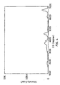
- the ⁇ -alumina supporting silver chloride thereon thus obtained was heated and calcined at 800°C for three hours in an air atmosphere containing 10% by weight of moisture, thereby providing a ⁇ -alumina powder catalyst supporting silver aluminate thereon in an amount of 5% by weight in terms of silver based on the catalyst.
- Fig. 1 shows an X-ray diffraction pattern of the thus obtained ⁇ -alumina supporting silver aluminate thereon in which circles indicate peaks due to silver aluminate; crosses indicate peaks due to alumina: and triangles indicate peaks due to silver.
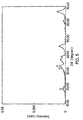
- Fig. 2 shows an X-ray diffraction pattern of the ⁇ -alumina used in the preparation of the catalyst shown in Fig. 1.
- ⁇ -alumina powder catalyst Sixty grams of the ⁇ -alumina powder catalyst were mixed with 6 g of silica sol (Snowtex N available from Nissan Kagaku Kogyo K.K.) and an appropriate amount of water. The mixture was ground with a planetary mill for five minutes using 100 g of zirconia balls as grinding media to prepare a wash coat slurry. A honeycomb substrate of cordierite having a cell number of 200 per square inch was coated with the slurry to provide a honeycomb catalyst structure supporting the catalyst in an amount of about 150 g/l. The thickness of the catalyst layer was 78 ⁇ m. This catalyst is designated as Catalyst A-1.
- a ⁇ -alumina powder catalyst supporting silver aluminate thereon in an amount of 3% by weight in terms of silver based on the catalyst was prepared in the same manner as in Example A-1, except for using 2.85 g of silver nitrate.
- the ⁇ -alumina powder. catalyst was supported on the same honeycomb substrate of cordierite as in Example A-1 to provide a honeycomb catalyst structure supporting the catalyst in an amount of about 150 g/l.
- the thickness of the catalyst layer was 85 ⁇ m. This catalyst is designated as Catalyst A-2.
- a ⁇ -alumina powder catalyst supporting silver aluminate thereon in an amount of 1% by weight in terms of silver based on the catalyst was prepared in the same manner as in Example A-1, except for using 0.95 g of silver nitrate.
- the ⁇ -alumina powder catalyst was supported on the same honeycomb substrate of cordierite as in Example A-1 to provide a honeycomb catalyst structure supporting the catalyst in an amount of about 150 g/l.
- the thickness of the catalyst layer was 88 ⁇ m. This catalyst is designated as Catalyst A-3.
- the paste was kneaded and dried by use of a heating kneader, and then heated and calcined at 800°C for three hours in an air atmosphere containing 10% by weight of moisture, thereby providing a ⁇ -alumina powder catalyst supporting silver aluminate thereon in an amount of 2.5% by weight in terms of silver based on the catalyst.
- the ⁇ -alumina powder catalyst was supported on the same honeycomb substrate of cordierite as in Example A-1 to provide a honeycomb catalyst structure supporting the catalyst in an amount of about 150 g/l.
- the thickness of the catalyst layer was 83 ⁇ m. This catalyst is designated as Catalyst A-4.
- Example A-1 One kilogram of the same ⁇ -alumina as in Example A-1 was kneaded with 79.2 g of silver nitrate, 1 kg of polyethylene oxide (PEO-10 available from Sumitomo Seika K.K.) and an appropriate amount of water. The mixture was extruded into a honeycomb structure having a cell number of 200 per square inch by use of an auger screw extruder. The honeycomb structure was air-dried at normal temperatures, dried overnight at 100°C, and then calcined at 500°C for three hours to prepare a honeycomb structure having a wall thickness of 205 ⁇ m and supporting silver (and/or silver oxide) thereon.
- PEO-10 polyethylene oxide
- honeycomb structure supporting silver (and/or silver oxide) was added to an aqueous hydrochloric solution to chlorinate the silver (and/or silver oxide), thereby providing a honeycomb structure supporting silver chloride in an amount of 5% by weight in terms of silver.
- the honeycomb structure was then heated and calcined at 800°C for three hours in an air atmosphere containing 10% by weight of moisture, thereby providing a ⁇ -alumina honeycomb catalyst structure supporting silver aluminate thereon in an amount of 5% by weight in terms of silver based on the catalyst.
- the honeycomb catalyst structure had a catalyst layer of 102 ⁇ m in thickness. This catalyst is designated as Catalyst A-5.
- the paste was kneaded and dried by use of a heating kneader, and then heated and calcined at 600°C for 18 hours in an air atmosphere containing 10% by weight of moisture, thereby providing a ⁇ -alumina powder catalyst supporting silver aluminate thereon in an amount of 2.5% by weight in terms of silver based on the catalyst,
- the ⁇ -alumina powder catalyst was supported on the same honeycomb substrate of cordierite as in Example A-1 to provide a honeycomb catalyst structure supporting the catalyst in an amount of about 150 g/l.
- the thickness of the catalyst layer was 71 ⁇ m. This catalyst is designated as Catalyst A-6.
- Fig. 3 shows an X-ray diffraction pattern of the thus obtained ⁇ -alumina/cordierite catalyst structure supporting silver aluminate thereon, in which circles indicate peaks due to silver aluminate and crosses indicate peaks due to alumina.
- Example A-1 One kilogram of the same ⁇ -alumina as in Example A-1 was kneaded with 79.2 g of silver nitrate, 1 kg of polyethylene oxide (PEO-10 available from Sumitomo Seika K.K.) and an appropriate amount of water. The mixture was extruded into a honeycomb structure having a cell number of 200 per square inch by use of an auger screw extruder. The honeycomb structure was air-dried at normal temperatures, dried overnight at 100°C, and then calcined at 500°C for three hours to prepare an alumina honeycomb structure having a wall thickness of 200 ⁇ m and supporting silver (and/or silver oxide) thereon.
- PEO-10 polyethylene oxide
- the honeycomb structure was then heated and calcined at 600°C for 18 hours in an air atmosphere containing 10% by weight of moisture, thereby providing a ⁇ -alumina honeycomb catalyst structure supporting silver aluminate thereon in an amount of 5% by weight in terms of silver based on the honeycomb catalyst structure.
- the honeycomb catalyst structure had a catalyst layer of 100 ⁇ m in thickness. This catalyst is designated as Catalyst A-7.
- the ⁇ -alumina powder catalyst supporting silver aluminate thereon in an amount of 5% by weight in terms of silver based on the catalyst as prepared in Example A-1 was wash-coated on a honeycomb substrate of cordierite to provide a honeycomb catalyst structure supporting the catalyst in an amount of about 100 g/l.
- the thickness of the catalyst layer was 52 ⁇ m. This catalyst is designated as Catalyst A-8.
- the ⁇ -alumina powder catalyst supporting silver aluminate thereon in an amount of 5% by weight in terms of silver based on the catalyst as prepared in Example A-1 was wash-coated on a honeycomb substrate of cordierite to provide a honeycomb catalyst structure supporting the catalyst in an amount of about 70 g/l.
- the thickness of the catalyst layer was 36 ⁇ m. This catalyst is designated as Catalyst A-9.
- a ⁇ -alumina powder catalyst supporting silver ions thereon in an amount of 5% by weight based on the catalyst was prepared in the same manner as in Example A-1.
- the ⁇ -alumina poder catalyst was coated on a honeycomb substrate of cordierite to provide a honeycomb catalyst structure supporting the powder catalyst in an amount of about 150 g/l.
- the thickness of the catalyst layer was 78 ⁇ m. This catalyst is designated as Catalyst A-10.
- the ⁇ -alumina honeycomb catalyst structure supporting silver (and/or silver oxide) in an amount of 5% by weight in terms of silver and having a wall thickness of 205 ⁇ m (i.e., having a catalyst layer of 102 ⁇ m in thickness) was used as it was as a catalyst A-11.
- the ⁇ -alumina powder catalyst supporting silver aluminate thereon in an amount of 5% by weight in terms of silver based on the catalyst as prepared in Example A-1 was wash-coated on a honeycomb substrate of cordierite to provide a honeycomb catalyst structure supporting the catalyst in an amount of about 50 g/l.
- the thickness of the catalyst layer was 26 ⁇ m. This catalyst is designated as Catalyst A-12.
- Example A-1 a honeycomb substrate of cordierite was coated with the ⁇ -alumina powder catalyst to provide a honeycomb catalyst structure supporting the catalyst in an amount of about 150 g/l.
- the thickness of the catalyst layer was 71 ⁇ m. This catalyst is designated as Catalyst A-13.
- Fig. 4 shows an X-ray diffraction pattern of the thus obtained ⁇ -alumina/cordierite catalyst.
- a ⁇ -alumina powder catalyst was prepared in the same manner as in Example A-13 except that the calcining temperature was 400°C.
- Example A-1 a honeycomb substrate of cordierite was coated with the ⁇ -alumina powder catalyst to provide a honeycomb catalyst structure supporting the catalyst in an amount of about 150 g/l.
- the thickness of the catalyst layer was found to be 71 ⁇ m. This catalyst is designated as Catalyst A-14.
- a ⁇ -alumina powder catalyst was prepared in the same manner as in Example A-13 except that the calcining temperature was 500°C.
- Example A-1 a honeycomb substrate of cordierite was coated with the ⁇ -alumina powder catalyst to provide a honeycomb catalyst structure supporting the catalyst in an amount of about 150 g/l.
- the thickness of the catalyst layer was 71 ⁇ m. This catalyst is designated as Catalyst A-15.
- Fig. 5 shows an X-ray diffraction pattern of the thus obtained ⁇ -alumina/cordierite catalyst.
- a ⁇ -alumina powder catalyst was prepared in the same manner as in Example A-13 except that the calcining temperature was 700°C.
- Example A-1 a honeycomb substrate of cordierite was coated with the ⁇ -alumina powder catalyst to provide a honeycomb catalyst structure supporting the catalyst in an amount of about 150 g/l.
- the thickness of the catalyst layer was 71 ⁇ m. This catalyst is designated as Catalyst A-16.
- Fig. 6 shows an X-ray diffraction pattern of the thus obtained ⁇ -alumina/cordierite catalyst.
- a ⁇ -alumina powder catalyst was prepared in the same manner as in Example A-13 except that the calcining temperature was 900°C.
- Example A-17 a honeycomb substrate of cordierite was coated with the ⁇ -alumina powder catalyst to provide a honeycomb catalyst structure supporting the catalyst in an amount of about 150 g/l.
- the thickness of the catalyst layer was found to be 71 ⁇ m. This catalyst is designated as Catalyst A-17.
- a ⁇ -alumina powder catalyst was prepared in the same manner as in Example A-13 except that the calcining temperature was 1000°C.
- Example A-18 a honeycomb substrate of cordierite was coated with the ⁇ -alumina powder catalyst to provide a honeycomb catalyst structure supporting the catalyst in an amount of about 150 g/l.
- the thickness of the catalyst layer was 71 ⁇ m. This catalyst is designated as Catalyst A-18.
- Fig. 7 shows an X-ray diffraction pattern of the thus obtained ⁇ -alumina/cordierite catalyst.
- a nitrogen oxide containing gas of which composition is shown below was first reduced at a temperature of 700°C and at a space velocity of 25000 h -1 for a period of 500 hours, and then the nitrogen oxide containing gas was reduced under the conditions (ii) and (iii) above specified. The resistance to heat and sulfur oxides of the catalysts were evaluated. The results are shown in Table 2.
- the catalysts of the invention achieves high conversion of nitrogen oxides, whereas the comparative castalysts have on the whole a low conversion rate of nitrogen oxides.
- the catalysts of the invention are durable even when they are used at high temperatures and excellent in resistance to sulfur oxides.
- Example A-1 In the same manner as in Example A-1, a ⁇ -alumina powder catalyst supporting silver aluminate thereon in an amount of 2.5% by weight in terms of silver based on the catalyst was prepared.
- ⁇ -alumina powder catalyst Sixty grams of the ⁇ -alumina powder catalyst were mixed with 6 g of silica sol (Snowtex N available from Nissan Kagaku Kogyo K.K.) and an appropriate amount of water. The mixture was ground with a planetary mill for five minutes using 100 g of zirconia balls as grinding media to prepare a wash coat slurry. A honeycomb substrate of cordierite having a cell number of 200 per square inch was coated with the slurry to provide a honeycomb catalyst structure supporting the catalyst in an amount of about 150 g/l. The thickness of the catalyst layer was 78 ⁇ m.
- honeycomb catalyst structure was then immersed in an aqueous solution of 0.088 g of ammonium molybdate ((NH 4 ) 6 Mo 7 O 24 ⁇ 4H 2 O) in 300 ml of ion-exchanged water for one hour.
- the honeycomb catalyst structure was taken out of the solution and excess solution adhering to the honeycomb catalyst structure was removed.
- honeycomb catalyst structure was then air-dried at normal temperatures and dried at 180°C for 12 hours, followed by calcining at 500°C for three hours, thereby providing a honeycomb catalyst structure supporting thereon a ⁇ -alumina catalyst composed of ⁇ -alumina which supported silver aluminate in an amount of 2.5% by weight in terms of silver and molybdenum trioxide (MoO 3 ) in an amount of 0.01% by weight in terms of molybdenum based on the ⁇ -alumina catalyst.
- This catalyst is designated as Catalyst B-1.
- a honeycomb catalyst structure supporting thereon a ⁇ -alumina catalyst composed of ⁇ -alumina which supported silver aluminate in an amount of 1.25% by weight in terms of silver and molybdenum trioxide (MoO 3 ) in an amount of 0.01% by weight in terms of molybdenum based on the ⁇ -alumina was prepared in the same manner as in Example B-1, except for using 1.19 g of silver nitrate.
- the ⁇ -alumina catalyst was supported on the honeycomb catalyst structure in an amount of about 150 g/l in a catalyst layer of 85 ⁇ m in thickness. This catalyst is designated as Catalyst B-2.
- a honeycomb catalyst structure supporting thereon a ⁇ -alumina catalyst composed of ⁇ -alumina which supported silver aluminate in an amount of 0.63% by weight in terms of silver and molybdenum trioxide (MoO 3 ) in an amount of 0.01% by weight in terms of molybdenum based on the ⁇ -alumina was prepared in the same manner as in Example B-1, except for using 0.60 g of silver nitrate.
- the ⁇ -alumina catalyst was supported on the honeycomb catalyst structure in an amount of about 150 g/l in a catalyst layer of 88 ⁇ m in thickness. This catalyst is designated as Catalyst B-3.
- the paste was kneaded and dried by use of a heating kneader, and then heated and calcined at 800°C for three hours in an air atmosphere containing 10% by weight of moisture, thereby providing a ⁇ -alumina catalyst supporting molybdenum trioxide (MoO 3 ) in an amount of 0.01% in terms of molybdenum and silver aluminate in an amount of 2.5% by weight in terms of silver based on the ⁇ -alumina catalyst.
- MoO 3 molybdenum trioxide
- the ⁇ -alumina powder catalyst was supported on the same honeycomb substrate of cordierite as in Example B-1 to provide a honeycomb catalyst structure supporting the catalyst in an amount of about 150 g/l.
- the thickness of the catalyst layer was 83 ⁇ m. This catalyst is designated as Catalyst B-4.
- One kilogram of aluminum hydroxide in terms of ⁇ -alumina was kneaded with 39.6 g of silver nitrate, 1.55 g of an ammonium metatungstate solution (50% by weight concentration as WO 3 , available from Shin-Nippon Kinzoku K.K.), 1 kg of polyethylene oxide (PEO-10 available from Sumitomo Seika K.K.) and an appropriate amount of water.
- the mixture was extruded into a honeycomb structure having a cell number of 200 per square inch by use of an auger screw extruder.
- honeycomb structure was air-dried at normal temperatures, dried at 100°C overnight, and then calcined at 500°C for three hours to prepare a ⁇ -alumina honeycomb structure having'a wall thickness of 205 ⁇ m and supporting thereon tungsten trioxide (WO 3 ) and silver (and/or silver oxide).
- tungsten trioxide WO 3
- silver and/or silver oxide
- honeycomb catalyst structure having a catalyst layer of 102 ⁇ m in thickness and supporting tungsten trioxide (WO 3 ) in an amount of 0.05% by weight in terms of tungsten and silver aluminate in an amount of 2.5% by weight in terms of silver based on the honeycomb catalyst structure.
- This catalyst is designated as Catalyst B-5.
- the paste was kneaded and dried by use of a heating kneader, and then heated and calcined at 600°C for 18 hours in an air atmosphere containing 10% by weight of moisture, thereby providing a ⁇ -alumina powder catalyst supporting molybdenum trioxide (MoO 3 ) in an amount of 0.01% by weight in terms of molybdenum and silver aluminate in an amount of 2.5% by weight in terms of silver based on the catalyst.
- MoO 3 molybdenum trioxide
- the ⁇ -alumina powder catalyst was supported on the same honeycomb substrate of cordierite as in Example B-1 to provide a honeycomb catalyst structure supporting the catalyst in an amount of about 150 g/l.
- the honeycomb catalyst structure had a catalyst layer of 71 ⁇ m in thickness. This catalyst is designated as Catalyst B-6.
- Example B-4 One kilogram (in terms of ⁇ -alumina) of the same hydrated alumina as in Example B-4, 31.7 g of silver nitrate, 1.24 g of an ammonium metatungstate solution (50% by weight concentration as WO 3 , available from Shin-Nippon Kinzoku K.K.), 1 kg of polyethylene oxide (PEO-10 available from Sumitomo Seika K.K.) were mixed and kneaded with an appropriate amount of water. The mixture was extruded into a honeycomb structure having a cell number of 200 per square inch by use of an auger screw extruder.
- PEO-10 polyethylene oxide
- honeycomb structure was air-dried at normal temperatures, dried at 100°C overnight, and then calcined at 500°C for three hours to prepare an ⁇ -alumina honeycomb structure having a wall thickness of 200 ⁇ m and supporting tungsten trioxide (WO 3 ) and silver (and/or silver oxide) thereon.
- tungsten trioxide WO 3
- silver and/or silver oxide
- the honeycomb structure was then heated and calcined at 600°C for 18 hours in an air atmosphere containing 10% by weight of moisture, thereby providing a ⁇ -alumina honeycomb catalyst structure having a catalyst layer of 100 ⁇ m in thickness and supporting tungsten trioxide in an amount of 0.01% by weight in terms of tungsten and silver aluminate in an amount of 2% by weight in terms of silver based on the honeycomb catalyst structure.
- This catalyst is designated as Catalyst B-7.
- the ⁇ -alumina powder catalyst supporting molybdenum trioxide (MoO 3 ) in an amount of 0.01% by weight in terms of molybdenum and silver aluminate in an amount of 2.5% by weight in terms of silver based on the catalyst as prepared in Example B-4 was wash-coated on a honeycomb substrate of cordierite to provide a honeycomb catalyst structure supporting the catalyst in an amount of about 100 g/l.
- the honeycomb catalyst structure had a catalyst layer of 52 ⁇ m in thickness. This catalyst is designated as Catalyst B-8.
- the ⁇ -alumina powder catalyst supporting molybdenum trioxide (MoO 3 ) in an amount of 0.01% by weight in terms of molybdenum and silver aluminate in an amount of 2.5% by weight in terms of silver based on the catalyst as prepared in Example B-4 was wash-coated on a honeycomb substrate of cordierite to provide a honeycomb catalyst structure supporting the catalyst in an amount of about 70 g/l.
- the honeycomb catalyst structure had a catalyst layer of 36 ⁇ m in thickness. This catalyst is designated as Catalyst B-9.
- the paste was kneaded and dried by use of a heating kneader, and then heated and calcined at 800°C for three hours in an air atmosphere containing 10% by weight of moisture, thereby providing a ⁇ -alumina powder catalyst supporting molybdenum trioxide (MoO 3 ) in an amount of 0.0001% by weight in terms of molybdenum and silver aluminate in an amount of 2.5% by weight in terms of silver based on the catalyst.
- MoO 3 molybdenum trioxide
- the ⁇ -alumina powder catalyst was supported on the same honeycomb substrate of cordierite as in Example B-1 to provide a honeycomb catalyst structure supporting the catalyst in an amount of about 145 g/l.
- the honeycomb catalyst structure had a catalyst layer of 80 ⁇ m in thickness. This catalyst is designated as Catalyst B-10.
- the paste was kneaded and dried by use of a heating kneader, and then heated and calcined at 800°C for three hours in an air atmosphere containing 10% by weight of moisture, thereby providing a ⁇ -alumina powder catalyst supporting molybdenum trioxide (MoO 3 ) in an amount of 0.05% by weight in terms of molybdenum and silver aluminate in an amount of 2.5% by weight in terms of silver based on the catalyst.
- MoO 3 molybdenum trioxide
- the ⁇ -alumina powder catalyst was supported on the same honeycomb substrate of cordierite as in Example B-1 to provide a honeycomb catalyst structure supporting the catalyst in an amount of about 140 g/l.
- the honeycomb catalyst structure had a catalyst layer of 77 ⁇ m in thickness. This catalyst is designated as Catalyst B-11.
- a ⁇ -alumina honeycomb catalyst structure having a catalyst layer of 200 ⁇ m in thickness and supporting tungsten trioxide (WO 3 ) in an amount of 0.05% by weight in terms of tungsten and silver aluminate in an amount of 2% by weight in terms of silver based on the catalyst structure was prepared in the same manner as in Example B-7, except for using 6.20 g of the ammonium metatungstate solution.
- This catalyst is designated as Catalyst B-12.
- the paste was kneaded and dried by use of a heating kneader, and then heated and calcined at 800°C for three hours in an air atmosphere containing 10% by weight of moisture, thereby providing a ⁇ -alumina powder catalyst supporting vanadium oxide (V 2 O 5 ) in an amount of 0.001% by weight in terms of vanadium and silver aluminate in an amount of 2.5% by weight in terms of silver based on the catalyst.
- V 2 O 5 vanadium oxide
- the ⁇ -alumina powder catalyst was supported on the same honeycomb substrate of cordierite as in Example B-1 to provide a honeycomb catalyst structure supporting the catalyst in an amount of about 150 g/l.
- the honeycomb catalyst structure had a catalyst layer of 85 ⁇ m in thickness. This catalyst is designated as Catalyst B-13.
- Example B-5 One kilogram (in terms of ⁇ -alumina) of the same aluminum hydroxide as used in Example B-5, 31.7 g of silver nitrate, 24.8 g of an ammonium metatungstate solution (50% by weight concentration as WO 3 , available from Shin-Nippon Kinzoku K.K.) and 1 kg of polyethylene oxide (PEO-10 available from Sumitomo Seika K.K.) were mixed with an appropriate amount of water. The mixture was thoroughly kneaded together and was extruded into a honeycomb structure having a cell number of 200 per square inch by use of an auger screw extruder.
- an ammonium metatungstate solution 50% by weight concentration as WO 3 , available from Shin-Nippon Kinzoku K.K.
- PEO-10 polyethylene oxide
- honeycomb structure was air-dried at normal temperatures, dried at 100°C overnight, and then calcined at 500°C for three hours to prepare a ⁇ -alumina honeycomb structure having a wall thickness of 200 ⁇ m and supporting tungsten trioxide (WO 3 ) and silver (and/or silver oxide) thereon.
- tungsten trioxide WO 3
- silver and/or silver oxide
- the honeycomb structure supporting tungsten trioxide and silver (and/or silver oxide) was heated and calcined at 600°C for 18 hours in an air atmosphere containing 10% by weight of moisture, thereby providing a ⁇ -alumina honeycomb catalyst structure having a catalyst layer of 200 ⁇ m in thickness and supporting tungsten trioxide (WO 3 ) in an amount of 0.2% by weight in terms of tungsten and silver aluminate in an amount of 2.0% by weight in terms of silver based on the ⁇ -alumina honeycomb catalyst structure.
- This catalyst is designated as Catalyst B-14.
- a ⁇ -alumina powder catalyst supporting silver ions thereon in an amount of 2.5% by weight based on the catalyst was prepared in the same manner as in Example B-1.
- the ⁇ -alumina powder catalyst was coated on a honeycomb substrate of cordierite to provide a honeycomb catalyst structure having a catalyst layer of 78 ⁇ m in thickness and supporting the catalyst in an amount of about 140 g/l.
- This catalyst is designated as Catalyst B-15.
- a ⁇ -alumina honeycomb catalyst structure having a wall thickness of 205 ⁇ m, a catalyst layer of 102 ⁇ m in thickness and supporting silver (and/or silver oxide) in an amount of 5% by weight in terms of silver based on the catalyst was prepared in the same manner as in Example B-5 except that the ammonium metatungstate solution was not used.
- This catalyst is designated as Catalyst B-16.
- the ⁇ -alumina powder catalyst supporting silver aluminate thereon in an amount of 2.5% by weight in terms of silver based on the catalyst as prepared in Example B-1 was wash-coated on a honeycomb substrate of cordierite to provide a honeycomb catalyst structure supporting the catalyst in an amount of about 50 g/l.
- the honeycomb catalyst structure had a catalyst layer of 26 ⁇ m in thickness. This catalyst is designated as Catalyst B-17.
- the ⁇ -alumina powder catalyst was supported on the same honeycomb substrate of cordierite as in Example B-1 to provide a honeycomb catalyst structure supporting the catalyst in an amount of about 150 g/l.
- the honeycomb catalyst structure bad a catalyst layer of 80 ⁇ m in thickness. This catalyst is designated as Catalyst B-18.
- the paste was kneaded and dried by use of a heating kneader, and then heated and calcined at 800°C for three hours in an air atmosphere containing 10% by weight of moisture, thereby providing a ⁇ -alumina powder catalyst supporting molybdenum trioxide (MoO 3 ) in an amount of 0.1% by weight and silver aluminate in an amount of 2.5% by weight in terms of silver based on the catalyst.
- MoO 3 molybdenum trioxide
- the ⁇ -alumina powder catalyst was supported on the same honeycomb substrate of cordierite as in Example B-1 to provide a honeycomb catalyst structure supporting the catalyst in an amount of about 150 g/l.
- the honeycomb catalyst structure had a catalyst layer of 80 ⁇ m in thickness. This catalyst is designated as Catalyst B-19.
- a nitrogen oxide containing gas of which composition is shown below was first reduced at a temperature of 700°C and at a space velocity of 25000 h -1 . for a period of 500 hours, and then the nitrogen oxide containing gas was reduced under the conditions (ii) and (iii) above specified. The resistance to heat and sulfur oxides of the catalysts were evaluated. The results are shown in Table 4.
- the catalysts of the invention achieves a high conversion of nitrogen oxides, whereas the comparative castalysts have on the whole a low conversion rate of nitrogen oxides.
- the catalysts of the invention are durable when being used at high temperatures and excellent in resistance to sulfur oxides.
- ⁇ -alumina powder catalyst Sixty grams of the ⁇ -alumina powder catalyst were mixed with 6 g of silica sol (Snowtex N available from Nissan Kagaku Kogyo K.K.) and an appropriate amount of water. The mixture was ground with a planetary mill for five minutes using 100 g of zirconia balls as grinding media to prepare a wash coat slurry. A honeycomb substrate of cordierite having a cell number of 200 per square inch was coated with the slurry to provide a honeycomb catalyst structure supporting the catalyst in an amount of about 150 g/l. This catalyst is designated as Catalyst C-11.
- silica-alumina having a specific surface area of 320 m 2 /g (available from Fuji-Davidson Chemical) and 6 g of silica sol (Snowtex N available from Nissan Kagaku Kogyo K.K.) were mixed with and an appropriate amount of water. The mixture was ground with a planetary mill for five minutes using 100 g of alumina balls as grinding media to prepare a wash coat slurry. A honeycomb substrate of cordierite having a cell number of 100 per square inch was coated with the slurry, dried and then calcined at 300°C for three hours to provide a honeycomb catalyst structure supporting the silica-alumina in an amount of about 200 g/l. This catalyst is designated as Catalyst C-21.
- Zircinium hydroxide was calcined at 500°C for three hours to prepare zirconia having a specific surface area of 80 m 2 /g.
- ⁇ -alumina honeycomb catalyst structure One kilogram of ⁇ -alumina having a specific surface area of 150 m 2 /g and 1 kg of polyethylene oxide were mixed with an appropriate amount of water. The mixture was extruded into a honeycomb structure having a cell number of 200 per square inch by use of an auger screw extruder. The honeycomb structure was air-dried at normal temperatures, dried at 100°C overnight, and then calcined at 500°C for three hours to prepare a ⁇ -alumina honeycomb catalyst structure. This catalyst is designated as Catalyst C-23.
- Metatitanic acid (TiO 2 ⁇ 2H 2 O) was calcined at 500°C for three hours to prepare titania having a specific surface area of 120 m 2 /g.
- Example C-3 Sixty grams of the titania and 6 g of silica sol (Snowtex N available from Nissan Kagaku Kogyo K.K.) were mixed with an appropriate amount of water. In the same manner as in Example C-3, a wash coat slurry was prepared, and by use thereof a honeycomb catalyst structure supporting the titania in an amount of about 200 g/l was prepared. This catalyst is designated as Catalyst C-24.
- a nitrogen oxide-containing gas was reduced under the conditions below.
- the conversion of nitrogen oxides to nitrogen was determined by gas chromatography based on the amount of nitrogen formed. That is, the conversion was calculated based on a formula: (nitrogen gas (ppm) in the exhaust gas after reduction treatment/nitrogen oxides (ppm) in the exhaus gas before reduction treatment) x 100 (%).
- concentrations of the ammonia and hydrogen cyanide formed in the reduction treatment of the exhaust gas were detected by use of a Kitagawa gas detector, and the formation rate was determined by a formula: (concentration (ppm) of ammonia or hydrogen cyanide in the exhaust gas after reduction treatment/concentration (ppm) of nitrogen gas (ppm) in the exhaust gas before reduction treatment) x 100 (%).
- the results are shown in Tables 5 and 6.
- the method of the invention achieves higher nitrogen oxide conversion if either gas oil or propylene is used as a reducing agent than the comparative method wherein the second catalyst alone is used.
- nitrogen oxides in exhaust gases are efficiently reduced by use of a reduced amount of a reducing agent and without undesirable by-oroduction of toxic nitrogen-containing compounds such as ammonia, amines or hydrogen cyanide.
- honeycomb structure was taken out of the solution and excess solution adhering to the structure was removed.
- the honeycomb structure was then dried at 100°C for 12 hours, followed by calcining at 500°C in air, thereby providing a honeycomb catalyst structure supporting the ⁇ -alumina catalyst composed of ⁇ -alumina which supported phosphoric acid in an amount of 2.0% by weight based on the ⁇ -alumina catalyst.
- This catalyst is designated as Catalyst D-11.
- Example D-1 An amount of 2.10 g of nickel chloride (NiCl 3 ) was dissolved in ion-exchanged water to prepare a solution in an amount of 30 ml.
- Example D-13 An amount of 4.33 g of nickel sulfate (NiSO 4 ⁇ 6H 2 O) was dissolved in ion-exchanged water to prepare a solution in an amount of 30 ml.
- Example D-14 An amount of 10.83 g of nickel sulfate (NiSO 4 ⁇ 6H 2 O) was dissolved in ion-exchanged water to prepare a solution in an amount of 30 ml.
- Example D-1 An amount of 0.43 g of nickel sulfate (NiSO 4 ⁇ 6H 2 O) was dissolved in ion-exchanged water to prepare a solution in an amount of 30 ml.
- Example D-1 An amount of 4.24 g of manganese sulfate (MnSO 4 ⁇ 5H 2 O) was dissolved in ion-exchanged water to prepare a solution in an amount of 30 ml.
- a honeycomb catalyst structure supporting a ⁇ -alumina catalyst composed of ⁇ -alumina which supported manganese sulfate in an amount of 2.0% by weight in terms of manganese based on the ⁇ -alumina catalyst. This catalyst is designated as Catalyst D-16.
- Example D-1 An amount of 1.52 g of silver nitrate (AgNO 3 ) was dissolved in ion-exchanged water to prepare a solution in an amount of 30 ml.
- a honeycomb structure supporting a catalyst composed of ⁇ -alumina supporting silver nitrate in an amount of 2.0% by weight in terms of silver based on the catalyst was then immersed in a 1% by weight aqueous hydrochloric acid solution to convert the silver nitrate to silver chloride, thereby providing a honeycomb catalyst structure supporting a ⁇ -alumina catalyst composed of ⁇ -alumina which supported silver chloride in an amount of 2.0% by weight in terms of silver based on the ⁇ -alumina catalyst.
- This catalyst is designated as Catalyst D-17.
- honeycomb structure was taken out of the solution and excess solution adhering to the structure was removed.
- the honeycomb structure was then dried at 100°C for 12 hours, followed by calcining at 500°C in air, thereby providing a honeycomb structure supporting a ⁇ -alumina catalyst composed of ⁇ -alumina which supported silver phosphate in an amount of 2.0% by weight in terms of silver based on the ⁇ -alumina catalyst.
- This catalyst is designated as Catalyst D-18.
- ⁇ -alumina powder catalyst Sixty grams of the ⁇ -alumina powder catalyst and 6 g of silica sol (Snowtex N available from Nissan Kagaku Kogyo K.K.) were mixed with an appropriate amount of water. The mixture was ground with a planetary mill for five minutes using 100 g of zirconia balls as grinding media to prepare a wash coat slurry. A honeycomb substrate of cordierite having a cell number of 200 per square inch was coated with the slurry to provide a honeycomb catalyst structure supporting the catalyst in an amount of about 150 g/l. This catalyst is designated as Catalyst D-21.
- the use of the first catalyst only results in very low conversion of nitrogen oxides.
- the use of the second catalyst only also results in generally low conversion of nitrogen oxides throughout the reaction temperatures tested.
- the method of the invention makes it possible to catalytically reduce nitrogen oxides in exhaust gases in a stable and efficient manner even in the presence of oxygen, sulfur oxides or moisture, with the use of a reducing agent in a reduced molar ratio of the reducing agent to nitrogen oxides.
Claims (10)
- Procédé de réduction catalytique d'oxydes d'azote contenus dans des gaz d'échappement, qui comprend mettre en contact le gaz d'échappement à une température de 100 - 800°C avec un catalyseur qui comprend de l'aluminate d'argent sur support d'alumine selon une quantité de 0,01 - 10% en poids en termes d'argent basé sur le catalyseur, en présence d'un hydrocarbure ou d'un composé organique contenant de l'oxygène en tant qu'agent de réduction.
- Procédé selon la revendication 1, dans lequel ladite température est de 200 à 500°C.
- Procédé selon la revendication 1 ou 2, dans lequel le catalyseur en est un produit en fixant au moins un membre sélectionné parmi l'argent, les halogénures d'argent, le nitrate d'argent, l'hydroxyde d'argent et l'oxyde d'argent, sur support d'alumine, et puis en calcinant le produit résultant dans une atmosphère oxydante en présence de 3 - 20% en poids de vapeur d'eau à une température de 600 - 900°C.
- Procédé selon la revendication 3, dans lequel l'halogénure d'argent est du chlorure d'argent.
- Procédé selon l'une quelconque des revendications précédentes, dans lequel ledit catalyseur comprend en outre au moins un élément de transition sélectionné parmi W, Mo et V sur support d'alumine selon une quantité totale dudit élément de transition de 0,0001-0,2% en poids en termes de métal basé sur le catalyseur.
- Procédé selon la revendication 5, dans lequel le catalyseur en est un produit en préparant une solution aqueuse de sel d'aluminium soluble dans l'eau, de sel d'argent soluble dans l'eau et d'un composé soluble dans l'eau du/des élément(s) de transition, en immergeant l'alumine dans la solution pour imprégner l'alumine avec le sel d'aluminium, le sel d'argent et le composé du/des élément(s) de transition, et en séchant et calcinant le produit résultant dans une atmosphère oxydante en présence de 3 - 20% en poids de vapeur d'eau à une température de 600 - 900°C.
- Procédé selon la revendication 6, dans lequel les sels d'aluminium et d'argent solubles dans l'eau sont des nitrates.
- Procédé selon la revendication 1, qui comprend une première étape dans laquelle le gaz d'échappement est mis en contact à une température de 250 - 550°C, avec un premier catalyseur qui est comme défini dans l'une quelconque des revendications précédentes, en présence d'un hydrocarbure en tant qu'agent de réduction, et une deuxième étape dans laquelle le gaz d'échappement est mis en contact à une température de 250 - 550°C avec un deuxième catalyseur qui comprend au moins l'un d'entre l'alumine, la silice-alumine, la zircone et le dioxyde de titane.
- Procédé selon la revendication 1, qui comprend une première étape dans laquelle le gaz d'échappement est mis en contact à une température de 150 - 650°C, avec un premier catalyseur qui comprend au moins un membre sélectionné parmi l'acide phosphorique et les phosphates, les chlorures et les sulfates des éléments des Groupes Ib, VIIa et VIII du tableau périodique des éléments, sur un support de matière porteuse selon une quantité de 0,05 - 5% en poids du catalyseur, et une deuxième étape dans laquelle le gaz d'échappement est mis en contact à une température de 150 - 650°C avec un deuxième catalyseur qui est comme défini dans l'une quelconque des revendications 1 à 7 en présence d'un hydrocarbure en tant qu'agent de réduction.
- Procédé selon la revendication 9, dans lequel les phosphates, les chlorures et les sulfates sont sélectionnés parmi le phosphate d'argent, le phosphate de cuivre, le phosphate de manganèse, le phosphate de fer, le phosphate de cobalt, le phosphate de nickel, le chlorure d'argent, le chlorure de cuivre, le chlorure de manganèse, le chlorure de fer, le chlorure de cobalt, le chlorure de nickel, le sulfate d'argent, le sulfate de cuivre, le sulfate de manganèse, le sulfate de fer, le sulfate de cobalt et le sulfate de nickel.
Applications Claiming Priority (9)
| Application Number | Priority Date | Filing Date | Title |
|---|---|---|---|
| JP22323/96 | 1996-02-08 | ||
| JP02232396A JP3453239B2 (ja) | 1995-08-18 | 1996-02-08 | 窒素酸化物接触還元用触媒 |
| JP2232396 | 1996-02-08 | ||
| JP312058/96 | 1996-11-22 | ||
| JP31205896 | 1996-11-22 | ||
| JP31205896A JP3872848B2 (ja) | 1996-11-22 | 1996-11-22 | 窒素酸化物接触還元用触媒 |
| JP1150897 | 1997-01-24 | ||
| JP01150897A JP3924341B2 (ja) | 1997-01-24 | 1997-01-24 | 窒素酸化物の接触還元方法 |
| JP11508/97 | 1997-01-24 |
Publications (2)
| Publication Number | Publication Date |
|---|---|
| EP0788829A1 EP0788829A1 (fr) | 1997-08-13 |
| EP0788829B1 true EP0788829B1 (fr) | 2004-09-22 |
Family
ID=27279452
Family Applications (1)
| Application Number | Title | Priority Date | Filing Date |
|---|---|---|---|
| EP97300816A Expired - Lifetime EP0788829B1 (fr) | 1996-02-08 | 1997-02-07 | Catalyseur et méthode pour la réduction catalytique d'oxydes d'azote |
Country Status (3)
| Country | Link |
|---|---|
| US (1) | US6045765A (fr) |
| EP (1) | EP0788829B1 (fr) |
| DE (1) | DE69730764T2 (fr) |
Families Citing this family (37)
| Publication number | Priority date | Publication date | Assignee | Title |
|---|---|---|---|---|
| GB2374559A (en) * | 2001-04-20 | 2002-10-23 | Accentus Plc | Removal of nitrogen oxides from effluent gases |
| US7257945B2 (en) * | 2003-02-10 | 2007-08-21 | U T Battelle, Llc | Stripping ethanol from ethanol-blended fuels for use in NOx SCR |
| US7000382B2 (en) * | 2003-07-02 | 2006-02-21 | General Motors Corporation | Partial oxidation of alcohols |
| JP4757027B2 (ja) * | 2003-11-11 | 2011-08-24 | 本田技研工業株式会社 | 窒素酸化物素酸化物を接触還元するための触媒 |
| US20050195966A1 (en) * | 2004-03-03 | 2005-09-08 | Sigma Dynamics, Inc. | Method and apparatus for optimizing the results produced by a prediction model |
| JP5628472B2 (ja) * | 2004-04-19 | 2014-11-19 | エスディーシーマテリアルズ, インコーポレイテッド | 気相合成による高スループットの材料発見方法 |
| DE102006031659A1 (de) * | 2006-07-08 | 2008-01-10 | Man Nutzfahrzeuge Aktiengesellschaft | Anordnung zur Verminderung von Stickoxiden in Abgasen |
| JP2008168228A (ja) * | 2007-01-12 | 2008-07-24 | Okayama Univ | 未燃カーボンを用いてディーゼルエンジン排ガス中の窒素酸化物を浄化するための触媒と方法 |
| JP4992773B2 (ja) * | 2007-03-20 | 2012-08-08 | 株式会社デンソー | 触媒材料 |
| JP2009219971A (ja) * | 2007-03-20 | 2009-10-01 | Denso Corp | セラミックハニカム構造体 |
| JP2009219972A (ja) * | 2007-03-20 | 2009-10-01 | Denso Corp | 触媒材料の製造方法 |
| US9173967B1 (en) | 2007-05-11 | 2015-11-03 | SDCmaterials, Inc. | System for and method of processing soft tissue and skin with fluids using temperature and pressure changes |
| US9272271B2 (en) * | 2007-09-19 | 2016-03-01 | General Electric Company | Manufacture of catalyst compositions and systems |
| US8530369B2 (en) * | 2007-09-19 | 2013-09-10 | General Electric Company | Catalyst and method of manufacture |
| US8507401B1 (en) | 2007-10-15 | 2013-08-13 | SDCmaterials, Inc. | Method and system for forming plug and play metal catalysts |
| CN102369159A (zh) * | 2009-01-30 | 2012-03-07 | 巴斯夫公司 | 用于从烃和氮氧化物来制备氨的催化剂 |
| US8178064B2 (en) * | 2009-05-11 | 2012-05-15 | Basf Corporation | Treatment of power utilities exhaust |
| US8470112B1 (en) | 2009-12-15 | 2013-06-25 | SDCmaterials, Inc. | Workflow for novel composite materials |
| US8545652B1 (en) | 2009-12-15 | 2013-10-01 | SDCmaterials, Inc. | Impact resistant material |
| US9126191B2 (en) | 2009-12-15 | 2015-09-08 | SDCmaterials, Inc. | Advanced catalysts for automotive applications |
| US9149797B2 (en) | 2009-12-15 | 2015-10-06 | SDCmaterials, Inc. | Catalyst production method and system |
| US8803025B2 (en) * | 2009-12-15 | 2014-08-12 | SDCmaterials, Inc. | Non-plugging D.C. plasma gun |
| US8557727B2 (en) | 2009-12-15 | 2013-10-15 | SDCmaterials, Inc. | Method of forming a catalyst with inhibited mobility of nano-active material |
| US9090475B1 (en) | 2009-12-15 | 2015-07-28 | SDCmaterials, Inc. | In situ oxide removal, dispersal and drying for silicon SiO2 |
| US8652992B2 (en) | 2009-12-15 | 2014-02-18 | SDCmaterials, Inc. | Pinning and affixing nano-active material |
| US20110143930A1 (en) * | 2009-12-15 | 2011-06-16 | SDCmaterials, Inc. | Tunable size of nano-active material on nano-support |
| US20110152068A1 (en) * | 2009-12-17 | 2011-06-23 | General Electric Company | Processing of high surface area oxides |
| US8669202B2 (en) | 2011-02-23 | 2014-03-11 | SDCmaterials, Inc. | Wet chemical and plasma methods of forming stable PtPd catalysts |
| CN103459792B (zh) | 2011-03-21 | 2016-10-05 | 沃尔沃技术公司 | 供应到催化转化器的还原剂中添加有活化剂材料的排气后处理系统 |
| MX2014001718A (es) | 2011-08-19 | 2014-03-26 | Sdcmaterials Inc | Sustratos recubiertos para uso en catalisis y convertidores cataliticos y metodos para recubrir sustratos con composiciones de recubrimiento delgado. |
| US9156025B2 (en) | 2012-11-21 | 2015-10-13 | SDCmaterials, Inc. | Three-way catalytic converter using nanoparticles |
| US9511352B2 (en) | 2012-11-21 | 2016-12-06 | SDCmaterials, Inc. | Three-way catalytic converter using nanoparticles |
| WO2015013545A1 (fr) | 2013-07-25 | 2015-01-29 | SDCmaterials, Inc. | Revêtements catalytiques et substrats revêtus pour convertisseurs catalytiques |
| US20150140317A1 (en) * | 2013-09-23 | 2015-05-21 | SDCmaterials, Inc. | High surface area catalyst |
| KR20160074566A (ko) | 2013-10-22 | 2016-06-28 | 에스디씨머티리얼스, 인코포레이티드 | 대형 디젤 연소 엔진용 촉매 디자인 |
| JP2016535664A (ja) | 2013-10-22 | 2016-11-17 | エスディーシーマテリアルズ, インコーポレイテッド | リーンNOxトラップの組成物 |
| US9687811B2 (en) | 2014-03-21 | 2017-06-27 | SDCmaterials, Inc. | Compositions for passive NOx adsorption (PNA) systems and methods of making and using same |
Family Cites Families (13)
| Publication number | Priority date | Publication date | Assignee | Title |
|---|---|---|---|---|
| US3565828A (en) * | 1969-07-11 | 1971-02-23 | Air Prod & Chem | Hydrated silver aluminate catalyst |
| US4092372A (en) * | 1975-04-03 | 1978-05-30 | Takeda Chemical Industries, Ltd. | Catalyst for the production of isoprene |
| JPS6186944A (ja) * | 1984-10-02 | 1986-05-02 | Matsushita Electric Ind Co Ltd | 排ガス浄化用触媒体 |
| JPH02261511A (ja) * | 1989-03-31 | 1990-10-24 | Komatsu Ltd | ディーゼル排気中の微粒子除去用触媒及びそのフィルタ |
| JPH04298235A (ja) * | 1991-03-27 | 1992-10-22 | Sekiyu Sangyo Kasseika Center | 窒素酸化物接触還元用触媒 |
| US5534237A (en) * | 1991-07-23 | 1996-07-09 | Kubushiki Kaisha Riken | Method of cleaning an exhaust gas and exhaust gas cleaner therefor |
| US5744111A (en) * | 1992-07-03 | 1998-04-28 | Kabushiki Kaisha Riken | Method for cleaning exhaust gas |
| US5714432A (en) * | 1992-12-28 | 1998-02-03 | Kabushiki Kaisha Riken | Exhaust gas cleaner comprising supported silver or silver oxide particles |
| EP0605251A1 (fr) * | 1992-12-28 | 1994-07-06 | Kabushiki Kaisha Riken | Epurateur de gaz d'échappement |
| EP0667182A3 (fr) * | 1994-02-10 | 1995-10-18 | Riken Kk | Epurateur de gaz d'échappement et méthode pour la purification de gaz d'échappement. |
| FR2718371B1 (fr) * | 1994-04-08 | 1996-05-03 | Rhone Poulenc Chimie | Catalyseurs de réduction des oxydes d'azote à base de spinelles. |
| US5658542A (en) * | 1994-07-15 | 1997-08-19 | Kabushiki Kaisha Riken | Exhaust gas cleaner and method for cleaning same |
| US5714130A (en) * | 1994-11-28 | 1998-02-03 | Kabushiki Kaisha Riken | Exhaust gas cleaner and method for cleaning exhaust gas |
-
1997
- 1997-02-07 DE DE69730764T patent/DE69730764T2/de not_active Expired - Lifetime
- 1997-02-07 EP EP97300816A patent/EP0788829B1/fr not_active Expired - Lifetime
- 1997-02-07 US US08/796,884 patent/US6045765A/en not_active Expired - Lifetime
Also Published As
| Publication number | Publication date |
|---|---|
| DE69730764T2 (de) | 2006-01-19 |
| US6045765A (en) | 2000-04-04 |
| DE69730764D1 (de) | 2004-10-28 |
| EP0788829A1 (fr) | 1997-08-13 |
Similar Documents
| Publication | Publication Date | Title |
|---|---|---|
| EP0788829B1 (fr) | Catalyseur et méthode pour la réduction catalytique d'oxydes d'azote | |
| US5733837A (en) | Catalyst for catalytic reduction of nitrogen oxides | |
| EP0596552A1 (fr) | Catalyseur de traitement des gaz d'échappement de moteur diesel contenant des particules | |
| WO2011116907A2 (fr) | Zrox, ce-zrox, ce-zr-reox au titre de matrices hôtes pour des cations à activité redox pour catalyseurs de réduction sélective à basse température, à durabilité hydrothermique satisfaisante et résistants à l'empoisonnement | |
| WO2002022255A1 (fr) | Catalyseur et procede de reduction catalytique d'oxydes d'azote | |
| WO2002089977A1 (fr) | Catalyseur et procede de reduction catalytique d'oxydes d'azote | |
| JP2838336B2 (ja) | 窒素酸化物接触還元用触媒 | |
| JP3453239B2 (ja) | 窒素酸化物接触還元用触媒 | |
| JP3872858B2 (ja) | 窒素酸化物の還元触媒の製造方法 | |
| JPH1199319A (ja) | 排ガス浄化方法 | |
| JP3930607B2 (ja) | 窒素酸化物接触還元用触媒 | |
| JP3791968B2 (ja) | 窒素酸化物の接触還元方法 | |
| JP3872848B2 (ja) | 窒素酸化物接触還元用触媒 | |
| JP3924341B2 (ja) | 窒素酸化物の接触還元方法 | |
| JP4088357B2 (ja) | 排ガス浄化方法 | |
| JPH11114420A (ja) | 排ガス浄化触媒及び方法 | |
| JPH1094718A (ja) | 窒素酸化物の接触還元方法 | |
| JPH09206559A (ja) | 窒素酸化物の接触還元方法 | |
| JP3781830B2 (ja) | 窒素酸化物の接触還元方法 | |
| JPH11197458A (ja) | 排ガス浄化方法 | |
| JPH11207182A (ja) | 窒素酸化物接触還元用触媒 | |
| JPH10244155A (ja) | 窒素酸化物接触還元用触媒 | |
| JP3495832B2 (ja) | 窒素酸化物の接触還元方法 | |
| JPH09201515A (ja) | 窒素酸化物の接触還元方法 | |
| JPH10314593A (ja) | 排ガス浄化触媒 |
Legal Events
| Date | Code | Title | Description |
|---|---|---|---|
| PUAI | Public reference made under article 153(3) epc to a published international application that has entered the european phase |
Free format text: ORIGINAL CODE: 0009012 |
|
| AK | Designated contracting states |
Kind code of ref document: A1 Designated state(s): DE FR GB IT |
|
| 17P | Request for examination filed |
Effective date: 19980209 |
|
| 17Q | First examination report despatched |
Effective date: 20020219 |
|
| GRAP | Despatch of communication of intention to grant a patent |
Free format text: ORIGINAL CODE: EPIDOSNIGR1 |
|
| RAP1 | Party data changed (applicant data changed or rights of an application transferred) |
Owner name: PETROLEUM ENERGY CENTER Owner name: SAKAI CHEMICAL INDUSTRY CO., LTD., |
|
| GRAS | Grant fee paid |
Free format text: ORIGINAL CODE: EPIDOSNIGR3 |
|
| GRAA | (expected) grant |
Free format text: ORIGINAL CODE: 0009210 |
|
| AK | Designated contracting states |
Kind code of ref document: B1 Designated state(s): DE FR GB IT |
|
| REG | Reference to a national code |
Ref country code: GB Ref legal event code: FG4D |
|
| REF | Corresponds to: |
Ref document number: 69730764 Country of ref document: DE Date of ref document: 20041028 Kind code of ref document: P |
|
| PLBE | No opposition filed within time limit |
Free format text: ORIGINAL CODE: 0009261 |
|
| STAA | Information on the status of an ep patent application or granted ep patent |
Free format text: STATUS: NO OPPOSITION FILED WITHIN TIME LIMIT |
|
| ET | Fr: translation filed | ||
| 26N | No opposition filed |
Effective date: 20050623 |
|
| REG | Reference to a national code |
Ref country code: FR Ref legal event code: CA Effective date: 20111007 |
|
| PGFP | Annual fee paid to national office [announced via postgrant information from national office to epo] |
Ref country code: FR Payment date: 20120221 Year of fee payment: 16 |
|
| PGFP | Annual fee paid to national office [announced via postgrant information from national office to epo] |
Ref country code: DE Payment date: 20120131 Year of fee payment: 16 |
|
| PGFP | Annual fee paid to national office [announced via postgrant information from national office to epo] |
Ref country code: GB Payment date: 20120201 Year of fee payment: 16 Ref country code: IT Payment date: 20120216 Year of fee payment: 16 |
|
| GBPC | Gb: european patent ceased through non-payment of renewal fee |
Effective date: 20130207 |
|
| REG | Reference to a national code |
Ref country code: FR Ref legal event code: ST Effective date: 20131031 |
|
| REG | Reference to a national code |
Ref country code: DE Ref legal event code: R119 Ref document number: 69730764 Country of ref document: DE Effective date: 20130903 |
|
| PG25 | Lapsed in a contracting state [announced via postgrant information from national office to epo] |
Ref country code: IT Free format text: LAPSE BECAUSE OF NON-PAYMENT OF DUE FEES Effective date: 20130207 |
|
| PG25 | Lapsed in a contracting state [announced via postgrant information from national office to epo] |
Ref country code: DE Free format text: LAPSE BECAUSE OF NON-PAYMENT OF DUE FEES Effective date: 20130903 Ref country code: GB Free format text: LAPSE BECAUSE OF NON-PAYMENT OF DUE FEES Effective date: 20130207 Ref country code: FR Free format text: LAPSE BECAUSE OF NON-PAYMENT OF DUE FEES Effective date: 20130228 |