EP0788760B1 - Einschaltgerät für einen Staubsauger - Google Patents
Einschaltgerät für einen Staubsauger Download PDFInfo
- Publication number
- EP0788760B1 EP0788760B1 EP96112776A EP96112776A EP0788760B1 EP 0788760 B1 EP0788760 B1 EP 0788760B1 EP 96112776 A EP96112776 A EP 96112776A EP 96112776 A EP96112776 A EP 96112776A EP 0788760 B1 EP0788760 B1 EP 0788760B1
- Authority
- EP
- European Patent Office
- Prior art keywords
- vacuum cleaner
- appliance
- switch
- consumer
- consumer terminal
- Prior art date
- Legal status (The legal status is an assumption and is not a legal conclusion. Google has not performed a legal analysis and makes no representation as to the accuracy of the status listed.)
- Expired - Lifetime
Links
Images


Classifications
-
- A—HUMAN NECESSITIES
- A47—FURNITURE; DOMESTIC ARTICLES OR APPLIANCES; COFFEE MILLS; SPICE MILLS; SUCTION CLEANERS IN GENERAL
- A47L—DOMESTIC WASHING OR CLEANING; SUCTION CLEANERS IN GENERAL
- A47L9/00—Details or accessories of suction cleaners, e.g. mechanical means for controlling the suction or for effecting pulsating action; Storing devices specially adapted to suction cleaners or parts thereof; Carrying-vehicles specially adapted for suction cleaners
- A47L9/28—Installation of the electric equipment, e.g. adaptation or attachment to the suction cleaner; Controlling suction cleaners by electric means
- A47L9/2857—User input or output elements for control, e.g. buttons, switches or displays
-
- A—HUMAN NECESSITIES
- A47—FURNITURE; DOMESTIC ARTICLES OR APPLIANCES; COFFEE MILLS; SPICE MILLS; SUCTION CLEANERS IN GENERAL
- A47L—DOMESTIC WASHING OR CLEANING; SUCTION CLEANERS IN GENERAL
- A47L9/00—Details or accessories of suction cleaners, e.g. mechanical means for controlling the suction or for effecting pulsating action; Storing devices specially adapted to suction cleaners or parts thereof; Carrying-vehicles specially adapted for suction cleaners
- A47L9/28—Installation of the electric equipment, e.g. adaptation or attachment to the suction cleaner; Controlling suction cleaners by electric means
- A47L9/2836—Installation of the electric equipment, e.g. adaptation or attachment to the suction cleaner; Controlling suction cleaners by electric means characterised by the parts which are controlled
- A47L9/2842—Suction motors or blowers
-
- H—ELECTRICITY
- H01—ELECTRIC ELEMENTS
- H01H—ELECTRIC SWITCHES; RELAYS; SELECTORS; EMERGENCY PROTECTIVE DEVICES
- H01H35/00—Switches operated by change of a physical condition
- H01H35/24—Switches operated by change of fluid pressure, by fluid pressure waves, or by change of fluid flow
- H01H35/247—Switches operated by change of fluid pressure, by fluid pressure waves, or by change of fluid flow the switch being of the reed switch type
Definitions
- the invention relates to a Vacuum cleaner that has an electrical consumer connection and an electrical one assigned to this consumer connection Has circuit that turns on the vacuum cleaner, if a connected to the consumer connection Consumer is switched on.
- Such a vacuum cleaner is for example in the EP 0 455 226 A2.
- Vacuum cleaners are becoming common used to extract dusts by tools arise when editing objects, for example when drilling or grinding. Usually acts these are electrically powered tools. The Extraction by the vacuum cleaner is only necessary as long as these tools are in use, that means the vacuum cleaner and the electrical tool are used closely coordinated. For this Basically, it is known to directly connect the tool to one Connect the consumer connection of the vacuum cleaner and to provide a switch-on device in the vacuum cleaner itself, which determines that the consumer connection a current flows, that is to this consumer connection connected tool is operated.
- US-A-4 238 689 describes one vacuum cleaner with a fixed switch, which is operated by hand.
- This switch has three Positions, in one position he connects an additional device the operating voltage of the vacuum cleaner, in a second position he breaks this connection and in a third position it connects the voltage source of the vacuum cleaner with one simulated consumer.
- This task is with a vacuum cleaner the beginning described type solved according to the invention, that one as a unit trained switch-on device on the vacuum cleaner releasably attached and with a cable and one to the consumer connection adapted connector is provided, and that to operate one not connected to the consumer connected device in the one connected to the consumer connection Switching device one of which is not connected to the Device connected to the consumer connection switching element actuable by its operation is provided, which during operation this device the consumer connection with an electrically simulated consumer connects.
- the device operated in this way can of course be very different, in particular this arrangement is favorable when operating tools of all kinds.
- Their drive can be varied external energy sources, it must be is by no means an electric drive, but other drives are possible, for example pneumatic or hydraulic drives. It is only essential that the switching on of the Device in any way the switching element in the starting device operated. This can all affect the professional common ways happen, for example by simple mechanical connections with the device or by measuring physical parameters on the device, the change with the operation of the same.
- the switch-on device a locking device for the line of the pneumatic Medium includes by an electrical monitoring circuit of the vacuum cleaner via the consumer connection and its connection to the switch-on device can be actuated. It is then possible to use the device also switch off from the vacuum cleaner by the Flow of the pneumatic medium is interrupted. This can be beneficial, for example, if Vacuum cleaner a monitoring circuit for effectiveness of the suction flow is present. If this Suction flow, for example, when the vacuum cleaner filter is dirty this monitoring circuit speaks too weak and delivers via the consumer connection a shutdown signal to the locking device in Switch-on device so that the device is switched off for safety reasons is because the vacuum of the vacuum cleaner is no longer effective enough.
- the switching element is a reed contact and that this is actuated by a magnet that movable depending on the operation or non-operation of the device is. This shifting movement could, for example done mechanically by a switch, which also turns on the device.
- a supply circuit for the electrical Switching elements of the switching device connected is whose electrical consumption is so low is that the electrical circuit of the vacuum cleaner not to be switched on by this consumption alone of the vacuum cleaner is activated.
- the line connection of the switching device to the consumer connection is therefore not used in this version only the simulated consumer to the consumer connection to connect, but also from the vacuum cleaner to supply the switching device with the operating energy, For example, amplifiers can be used in the switching device and relays can be provided, the switching element operate or, if necessary, a locking device.
- the electrical consumption of the switching device is included usually very low and therefore it is possible the supply via the consumer connection of the Vacuum cleaner to do without the vacuum cleaner assigned circuit solely because of this low Already switches on the vacuum cleaner. It is sufficient this circuit with threshold detection to be provided so that the activation of the vacuum cleaner only takes place if that over the consumer connection flowing current a certain threshold exceeds. This threshold is so chosen to be above the supply level of the starting device is necessary, however under the value that a usually to the consumer connection connected consumer required.
- a conventional vacuum cleaner 1 is shown schematically in FIG shown with an intake manifold 2, a large one Dirt collecting container 3 and with one placed on it Suction unit, which is not specifically shown in the drawing is shown.
- the suction unit connects the Dirt collecting container 3 via a likewise not shown Filter with the environment so that through the Intake 2 a suction flow through the dirt collector 3 and the filter directed into the environment can be.
- a connectable to the intake manifold 2 flexible hose line can thus Vacuum dirt and dust particles and in Collect dirt collecting container 3. So far it is the vacuum cleaner 1 is a conventional one Vacuum cleaner, as is readily known to the expert is.
- the vacuum cleaner 1 has an electrical consumer connection 4, which is preferably in the form of a normal power socket.
- an electrical consumer can be connected an electric drill, for example, an electric grinder or the like, the over the consumer connection 4 with the necessary Operating energy is supplied.
- an electric one Circuit 5 arranged, which determines whether over the Consumer terminal 4 a current flows. Is this the Case, this circuit 5 activates the electric motor of the Vacuum cleaner 1, so that the vacuum cleaner thereby in operation is set. Such a current flow is absent the consumer connection 4, the vacuum cleaner 1, if necessary switched off with a time delay. It is because of it possible to synchronize the vacuum cleaner with one at the Consumer connection 4 connected consumers, for example to operate an electrical tool.
- a switching device 8 which is designed as a box-shaped unit is.
- This switch-on device 8 is by means of a bracket 9 hung on the vacuum cleaner 1 and thereby releasably held this.
- the switch-on device 8 has one at one end Connection 10 for a line 21 of a pneumatic Medium, for example for compressed air. On is further connection 11 for a pneumatic medium on the opposite side of the switching device arranged.
- Connections 10 and 11 follow on the inside of the switching device 8 each have a blind hole 12 or 13 on ( Figures 2 to 4), which are so dense abut each other so that they overlap at least partially and thus a continuous connection between form the connections 10 and 11.
- a magnetic piston 14 slidably mounted on which one in the Blind hole 12 arranged and located at the bottom 15 supporting coil spring 16 supports.
- the piston 14 is usually by the coil spring 16 moved into a region of the blind hole 12, which has no connection to the adjacent blind hole 13 ( Figures 2 and 3). However, will the port 10 supplied pneumatic medium, shifts the piston 14 through this pneumatic Flow and gives the connection to the neighboring Blind hole 13 free ( Figure 4). Im flowed through State is therefore the piston 14 against the action of Coil spring 16 moved, in the non-flowed on the other hand, not shifted.
- the piston 14 is designed and actuated as a magnet a reed contact 17, which runs along the blind hole 12 is arranged. Depending on the position of the magnetic piston 14, the reed contact 17 is opened once (FIG 3), once closed ( Figure 4).
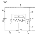
- switch 19 When switch 19 is open, line 18 is interrupted, so that the consumer connection 4 is not a consumer "recognizes” that a current cannot flow. Becomes the switch 19, however, closed, flows from the consumer connection 4 a current through the capacitor 20.
- This capacitor 20 forms a reactance, of the electrical circuit 5 in the vacuum cleaner 1 is recognized as a consumer, and this circuit 5 switches on the vacuum cleaner 1 in this case.
- the switch 19 is only closed as long as it is external operated device is in operation, so long for example the blind holes 12 and 13 of Compressed air flow.
- the switch 19 When switching off the device and the interruption of this compressed air flow opens the reed contact 17 and this leads to the opening of the switch 19. This makes the vacuum cleaner 1 over the circuit 5 switched off.
Landscapes
- Engineering & Computer Science (AREA)
- Mechanical Engineering (AREA)
- Physics & Mathematics (AREA)
- Fluid Mechanics (AREA)
- Electric Vacuum Cleaner (AREA)
- Switches With Compound Operations (AREA)
- Switches Operated By Changes In Physical Conditions (AREA)
- Keying Circuit Devices (AREA)
Description
- Figur 1:
- eine schematische Seitenansicht eines Staubsaugers mit einem Verbraucheranschluß und einem aufgesetzten Einschaltgerät ohne daran angeschlossenes extern betriebenes Gerät;
- Figur 2:
- ein bevorzugtes Ausführungsbeispiel eines Schaltglieds für ein Einschaltgerät mit einem verschiebbaren Magneten zur Schaltung eines Reedkontakts im Längsschnitt längs Linie 2-2 in Figur 3;
- Figur 3:
- eine Längsschnittansicht längs Linie 3-3 in Figur 2 bei fehlender Durchströmung;
- Figur 4:
- eine Ansicht ähnlich Figur 3 mit Durchströmung und
- Figur 5:
- eine schematische Schaltung eines Einschaltgeräts.
Claims (9)
- Staubsauger, der einen elektrischen Verbraucheranschluß (4) und eine diesem Verbraucheranschluß (4) zugeordnete elektrische Schaltung aufweist, die den Staubsauger einschaltet, wenn ein an den Verbraucheranschluß (4) angeschlossener Verbraucher (20) eingeschaltet wird, dadurch gekennzeichnet, daß ein als Baueinheit ausgebildetes Einschaltgerät am Staubsauger (1) lösbar befestigt und mit einem Kabel (6) und einem an den Verbraucheranschluß (4) angepaßten Anschlußstück (7) versehen ist, und daß zum Betrieb eines nicht an den Verbraucheranschluß (4) angeschlossenen Geräts in dem am Verbraucheranschluß (4) angeschlossenen Einschaltgerät (8) ein von dem nicht an den Verbraucheranschluß angeschlossenen Gerät abhängig von dessen Betrieb betätigbares Schaltglied (19) vorgesehen ist, welches beim Betrieb dieses Geräts den Verbraucheranschluß (4) mit einem elektrisch simulierten Verbraucher (20) verbindet.
- Staubsauger nach Anspruch 1, dadurch gekennzeichnet, daß der elektrisch simulierte Verbraucher (20) ein Blindwiderstand ist.
- Staubsauger nach Anspruch 2, dadurch gekennzeichnet, daß der elektrisch simulierte Verbraucher (20) ein Kondensator ist.
- Staubsauger nach einem der voranstehenden. Ansprüche, dadurch gekennzeichnet, daß das Einschaltgerät bei einem pneumatisch angetriebenen Gerät in die Leitung (21) des pneumatischen Mediums eingeschaltet ist und durch den Strom des pneumatischen Mediums betätigt wird.
- Staubsauger nach Anspruch 4, dadurch gekennzeichnet, daß das Einschaltgerät eine Schließeinrichtung (22) für die Leitung (21) des pneumatischen Mediums umfaßt, die von einer elektrischen Überwachungsschaltung des Staubsaugers (1) über den Verbraucheranschluß (4) und dessen Verbindung (6) mit dem Einschaltgerät (8) betätigbar ist.
- Staubsauger nach einem der voranstehenden Ansprüche, dadurch gekennzeichnet, daß das Schaltglied ein Reedkontakt (17) ist und daß dieser durch einen Magneten (14) betätigt wird, der abhängig vom Betrieb oder Nichtbetrieb des Geräts verschiebbar ist.
- Staubsauger nach Anspruch 6, dadurch gekennzeichnet, daß der Magnet (14) bei einem pneumatisch betriebenen Gerät von dem das Gerät antreibenden Gasstrom verschiebbar ist.
- Staubsauger nach Anspruch 7, dadurch gekennzeichnet, daß der Magnet (14) ein in einem Strömungskanal (12) des Gasstroms gegen die Wirkung einer elastischen Rückstellkraft verschiebbarer Kolben ist.
- Staubsauger nach einem der voranstehenden Ansprüche, dadurch gekennzeichnet, daß an die Verbindung des Einschaltgeräts zum Verbraucheranschluß (4) eine Versorgungsschaltung für die elektrischen Schaltelemente des Einschaltgeräts (8) angeschlossen ist, deren elektrischer Verbrauch so niedrig ist, daß die elektrische Schaltung (5) des Staubsaugers (1) durch diesen Verbrauch allein noch nicht zur Einschaltung des Staubsaugers (1) aktiviert wird.
Applications Claiming Priority (2)
| Application Number | Priority Date | Filing Date | Title |
|---|---|---|---|
| DE19530187 | 1995-08-17 | ||
| DE19530187A DE19530187C1 (de) | 1995-08-17 | 1995-08-17 | Einschaltgerät für einen Staubsauger |
Publications (3)
| Publication Number | Publication Date |
|---|---|
| EP0788760A2 EP0788760A2 (de) | 1997-08-13 |
| EP0788760A3 EP0788760A3 (de) | 1998-06-03 |
| EP0788760B1 true EP0788760B1 (de) | 2001-05-23 |
Family
ID=7769663
Family Applications (1)
| Application Number | Title | Priority Date | Filing Date |
|---|---|---|---|
| EP96112776A Expired - Lifetime EP0788760B1 (de) | 1995-08-17 | 1996-08-08 | Einschaltgerät für einen Staubsauger |
Country Status (3)
| Country | Link |
|---|---|
| EP (1) | EP0788760B1 (de) |
| AT (1) | ATE201314T1 (de) |
| DE (2) | DE19530187C1 (de) |
Families Citing this family (3)
| Publication number | Priority date | Publication date | Assignee | Title |
|---|---|---|---|---|
| DE19736595B4 (de) * | 1997-08-22 | 2007-04-12 | BSH Bosch und Siemens Hausgeräte GmbH | Drahtlose Fernbetätigungseinrichtung für einen Staubsauger |
| DE10134062A1 (de) * | 2001-07-13 | 2003-01-30 | Alto Deutschland Gmbh | Schmutzsauger mit druckluftbetätigter Einschaltautomatik |
| DE102009015642B4 (de) * | 2009-03-21 | 2025-09-18 | Festool Gmbh | Sauggerät mit Funktionsmodul |
Family Cites Families (3)
| Publication number | Priority date | Publication date | Assignee | Title |
|---|---|---|---|---|
| US4238689A (en) * | 1979-02-28 | 1980-12-09 | Beamco Co., Inc. | Vacuum cleaner control system |
| US5099157A (en) * | 1988-06-10 | 1992-03-24 | Milwaukee Electric Tool Corporation | Master/slave circuit employing triacs |
| DE9005070U1 (de) * | 1990-05-04 | 1991-06-20 | WAP Reinigungssysteme GmbH & Co, 7919 Bellenberg | Einschaltautomatik für ein Absauggerät |
-
1995
- 1995-08-17 DE DE19530187A patent/DE19530187C1/de not_active Expired - Fee Related
-
1996
- 1996-08-08 EP EP96112776A patent/EP0788760B1/de not_active Expired - Lifetime
- 1996-08-08 AT AT96112776T patent/ATE201314T1/de not_active IP Right Cessation
- 1996-08-08 DE DE59606954T patent/DE59606954D1/de not_active Expired - Fee Related
Also Published As
| Publication number | Publication date |
|---|---|
| EP0788760A3 (de) | 1998-06-03 |
| EP0788760A2 (de) | 1997-08-13 |
| ATE201314T1 (de) | 2001-06-15 |
| DE19530187C1 (de) | 1996-08-29 |
| DE59606954D1 (de) | 2001-06-28 |
Similar Documents
| Publication | Publication Date | Title |
|---|---|---|
| EP2046183B1 (de) | Verfahren zum abreinigen der filter eines staubsaugers sowie staubsauger zur durchführung des verfahrens | |
| EP2457485B1 (de) | Verfahren zum Abreinigen der Filter eines Staubsaugers sowie Staubsauger zur Durchführung des Verfahrens | |
| DE69023165T2 (de) | Fernbedienungsgerät für Saug- oder Lüftungssystem. | |
| DE2749480A1 (de) | Filter eines reinigungsgeraetes | |
| EP2063443B1 (de) | Not-Aus-Schaltvorrichtung | |
| DE102015100057A1 (de) | Staubsauger | |
| EP2046182A1 (de) | Staubsauger mit filterselbstreinigungsvorrichtung | |
| EP2575585A1 (de) | Staubsauger mit fremdluftventil zur filterabreinigung | |
| DE102020116426A1 (de) | Saugreinigungsgerät | |
| DE1186992B (de) | Automatischer Staubsauger | |
| DE3247490C2 (de) | ||
| DE102013108559A1 (de) | Verfahren zum Betrieb eines Staubsaugers zum Rückreinigen eines vom Staubsauger umfassten Filterelements | |
| DE19530187C1 (de) | Einschaltgerät für einen Staubsauger | |
| DE10101218B4 (de) | Schmutzsauger | |
| DE3034589C2 (de) | Vorrichtung zum Sichern für die öffenbaren Teile von Schutzabdeckungen bei Textilmaschinen | |
| DE3412545A1 (de) | Automatisch steuerbare ventileinrichtung | |
| DE102022125214A1 (de) | Filtervorrichtungsbaugruppe mit passiver Bypass-Schaltereinheit | |
| DE2810707C2 (de) | Elektro-mechanische Zweihand-Sicherheitsschaltung | |
| DE2800877A1 (de) | Pneumatisches hilfsaggregat fuer das heben des stromabnehmers einer elektrischen lokomotive | |
| DE2923536A1 (de) | Alarm- und steuergeraet fuer austretende leitende fluessigkeiten mit akustischer signalgabe und gleichzeitiger schliessung eines zugehoerigen magnetventiles zur anwendung bei wasch-, geschirrspuelmaschinen usw. | |
| EP1186506A2 (de) | Kupplungskopf für eine starre, automatische Mittelkupplung von Schienenfahrzeugen | |
| EP3320822B1 (de) | Sauggerät mit einer anschlussvorrichtung | |
| DE4305303C2 (de) | Sauggerät für Reinigungszwecke | |
| DE1097632B (de) | UEberwachungseinrichtung an Haushalts- und Industriestaubsaugern | |
| DE10102565C2 (de) | Aschenbecherabsaugungsanlage |
Legal Events
| Date | Code | Title | Description |
|---|---|---|---|
| PUAI | Public reference made under article 153(3) epc to a published international application that has entered the european phase |
Free format text: ORIGINAL CODE: 0009012 |
|
| AK | Designated contracting states |
Kind code of ref document: A2 Designated state(s): AT BE CH DE DK ES FR GB GR IE IT LI LU MC NL PT SE |
|
| PUAL | Search report despatched |
Free format text: ORIGINAL CODE: 0009013 |
|
| AK | Designated contracting states |
Kind code of ref document: A3 Designated state(s): AT BE CH DE DK ES FR GB GR IE IT LI LU MC NL PT SE |
|
| 17P | Request for examination filed |
Effective date: 19981203 |
|
| 17Q | First examination report despatched |
Effective date: 19990409 |
|
| GRAG | Despatch of communication of intention to grant |
Free format text: ORIGINAL CODE: EPIDOS AGRA |
|
| GRAG | Despatch of communication of intention to grant |
Free format text: ORIGINAL CODE: EPIDOS AGRA |
|
| GRAH | Despatch of communication of intention to grant a patent |
Free format text: ORIGINAL CODE: EPIDOS IGRA |
|
| GRAH | Despatch of communication of intention to grant a patent |
Free format text: ORIGINAL CODE: EPIDOS IGRA |
|
| GRAA | (expected) grant |
Free format text: ORIGINAL CODE: 0009210 |
|
| ITF | It: translation for a ep patent filed | ||
| AK | Designated contracting states |
Kind code of ref document: B1 Designated state(s): AT BE CH DE DK ES FR GB GR IE IT LI LU MC NL PT SE |
|
| PG25 | Lapsed in a contracting state [announced via postgrant information from national office to epo] |
Ref country code: NL Free format text: LAPSE BECAUSE OF FAILURE TO SUBMIT A TRANSLATION OF THE DESCRIPTION OR TO PAY THE FEE WITHIN THE PRESCRIBED TIME-LIMIT Effective date: 20010523 Ref country code: IE Free format text: LAPSE BECAUSE OF FAILURE TO SUBMIT A TRANSLATION OF THE DESCRIPTION OR TO PAY THE FEE WITHIN THE PRESCRIBED TIME-LIMIT Effective date: 20010523 Ref country code: GB Free format text: LAPSE BECAUSE OF FAILURE TO SUBMIT A TRANSLATION OF THE DESCRIPTION OR TO PAY THE FEE WITHIN THE PRESCRIBED TIME-LIMIT Effective date: 20010523 Ref country code: FR Free format text: LAPSE BECAUSE OF FAILURE TO SUBMIT A TRANSLATION OF THE DESCRIPTION OR TO PAY THE FEE WITHIN THE PRESCRIBED TIME-LIMIT Effective date: 20010523 |
|
| REF | Corresponds to: |
Ref document number: 201314 Country of ref document: AT Date of ref document: 20010615 Kind code of ref document: T |
|
| REG | Reference to a national code |
Ref country code: CH Ref legal event code: EP |
|
| REF | Corresponds to: |
Ref document number: 59606954 Country of ref document: DE Date of ref document: 20010628 |
|
| REG | Reference to a national code |
Ref country code: IE Ref legal event code: FG4D Free format text: GERMAN |
|
| PG25 | Lapsed in a contracting state [announced via postgrant information from national office to epo] |
Ref country code: LU Free format text: LAPSE BECAUSE OF NON-PAYMENT OF DUE FEES Effective date: 20010808 Ref country code: AT Free format text: LAPSE BECAUSE OF NON-PAYMENT OF DUE FEES Effective date: 20010808 |
|
| PG25 | Lapsed in a contracting state [announced via postgrant information from national office to epo] |
Ref country code: PT Free format text: LAPSE BECAUSE OF FAILURE TO SUBMIT A TRANSLATION OF THE DESCRIPTION OR TO PAY THE FEE WITHIN THE PRESCRIBED TIME-LIMIT Effective date: 20010823 Ref country code: DK Free format text: LAPSE BECAUSE OF FAILURE TO SUBMIT A TRANSLATION OF THE DESCRIPTION OR TO PAY THE FEE WITHIN THE PRESCRIBED TIME-LIMIT Effective date: 20010823 |
|
| PG25 | Lapsed in a contracting state [announced via postgrant information from national office to epo] |
Ref country code: GR Free format text: LAPSE BECAUSE OF FAILURE TO SUBMIT A TRANSLATION OF THE DESCRIPTION OR TO PAY THE FEE WITHIN THE PRESCRIBED TIME-LIMIT Effective date: 20010824 |
|
| PG25 | Lapsed in a contracting state [announced via postgrant information from national office to epo] |
Ref country code: LI Free format text: LAPSE BECAUSE OF NON-PAYMENT OF DUE FEES Effective date: 20010831 Ref country code: CH Free format text: LAPSE BECAUSE OF NON-PAYMENT OF DUE FEES Effective date: 20010831 Ref country code: BE Free format text: LAPSE BECAUSE OF NON-PAYMENT OF DUE FEES Effective date: 20010831 |
|
| NLV1 | Nl: lapsed or annulled due to failure to fulfill the requirements of art. 29p and 29m of the patents act | ||
| GBV | Gb: ep patent (uk) treated as always having been void in accordance with gb section 77(7)/1977 [no translation filed] |
Effective date: 20010523 |
|
| PG25 | Lapsed in a contracting state [announced via postgrant information from national office to epo] |
Ref country code: ES Free format text: LAPSE BECAUSE OF FAILURE TO SUBMIT A TRANSLATION OF THE DESCRIPTION OR TO PAY THE FEE WITHIN THE PRESCRIBED TIME-LIMIT Effective date: 20011130 |
|
| EN | Fr: translation not filed | ||
| REG | Reference to a national code |
Ref country code: IE Ref legal event code: FD4D |
|
| BERE | Be: lapsed |
Owner name: ALFRED KARCHER G.M.B.H. & CO. Effective date: 20010831 |
|
| PG25 | Lapsed in a contracting state [announced via postgrant information from national office to epo] |
Ref country code: MC Free format text: LAPSE BECAUSE OF NON-PAYMENT OF DUE FEES Effective date: 20020301 |
|
| PLBE | No opposition filed within time limit |
Free format text: ORIGINAL CODE: 0009261 |
|
| STAA | Information on the status of an ep patent application or granted ep patent |
Free format text: STATUS: NO OPPOSITION FILED WITHIN TIME LIMIT |
|
| REG | Reference to a national code |
Ref country code: CH Ref legal event code: PL |
|
| 26N | No opposition filed | ||
| PGFP | Annual fee paid to national office [announced via postgrant information from national office to epo] |
Ref country code: SE Payment date: 20030728 Year of fee payment: 8 |
|
| PG25 | Lapsed in a contracting state [announced via postgrant information from national office to epo] |
Ref country code: SE Free format text: LAPSE BECAUSE OF NON-PAYMENT OF DUE FEES Effective date: 20040809 |
|
| PGFP | Annual fee paid to national office [announced via postgrant information from national office to epo] |
Ref country code: DE Payment date: 20040927 Year of fee payment: 9 |
|
| EUG | Se: european patent has lapsed | ||
| PG25 | Lapsed in a contracting state [announced via postgrant information from national office to epo] |
Ref country code: IT Free format text: LAPSE BECAUSE OF NON-PAYMENT OF DUE FEES Effective date: 20050808 |
|
| PG25 | Lapsed in a contracting state [announced via postgrant information from national office to epo] |
Ref country code: DE Free format text: LAPSE BECAUSE OF NON-PAYMENT OF DUE FEES Effective date: 20060301 |