EP0788226B1 - Schaltungsanordnung eines Rundfunkempfängers - Google Patents
Schaltungsanordnung eines Rundfunkempfängers Download PDFInfo
- Publication number
- EP0788226B1 EP0788226B1 EP97100901A EP97100901A EP0788226B1 EP 0788226 B1 EP0788226 B1 EP 0788226B1 EP 97100901 A EP97100901 A EP 97100901A EP 97100901 A EP97100901 A EP 97100901A EP 0788226 B1 EP0788226 B1 EP 0788226B1
- Authority
- EP
- European Patent Office
- Prior art keywords
- frequency
- circuit
- signal
- stop signal
- station search
- Prior art date
- Legal status (The legal status is an assumption and is not a legal conclusion. Google has not performed a legal analysis and makes no representation as to the accuracy of the status listed.)
- Expired - Lifetime
Links
- 239000003990 capacitor Substances 0.000 claims description 41
- 239000000919 ceramic Substances 0.000 claims description 33
- 238000009499 grossing Methods 0.000 claims description 5
- 238000009966 trimming Methods 0.000 claims description 2
- 208000033766 Prolymphocytic Leukemia Diseases 0.000 description 5
- 230000001960 triggered effect Effects 0.000 description 4
- 230000008878 coupling Effects 0.000 description 3
- 238000010168 coupling process Methods 0.000 description 3
- 238000005859 coupling reaction Methods 0.000 description 3
- 230000001419 dependent effect Effects 0.000 description 3
- 238000010586 diagram Methods 0.000 description 2
- 238000001914 filtration Methods 0.000 description 2
- 238000000034 method Methods 0.000 description 2
- 239000013078 crystal Substances 0.000 description 1
- 238000001514 detection method Methods 0.000 description 1
- 238000011161 development Methods 0.000 description 1
- 230000018109 developmental process Effects 0.000 description 1
- 238000011156 evaluation Methods 0.000 description 1
- 238000004519 manufacturing process Methods 0.000 description 1
- 239000010453 quartz Substances 0.000 description 1
- 230000001105 regulatory effect Effects 0.000 description 1
- 238000000926 separation method Methods 0.000 description 1
- VYPSYNLAJGMNEJ-UHFFFAOYSA-N silicon dioxide Inorganic materials O=[Si]=O VYPSYNLAJGMNEJ-UHFFFAOYSA-N 0.000 description 1
Images

Classifications
-
- H—ELECTRICITY
- H03—ELECTRONIC CIRCUITRY
- H03J—TUNING RESONANT CIRCUITS; SELECTING RESONANT CIRCUITS
- H03J7/00—Automatic frequency control; Automatic scanning over a band of frequencies
- H03J7/18—Automatic scanning over a band of frequencies
- H03J7/20—Automatic scanning over a band of frequencies where the scanning is accomplished by varying the electrical characteristics of a non-mechanically adjustable element
- H03J7/24—Automatic scanning over a band of frequencies where the scanning is accomplished by varying the electrical characteristics of a non-mechanically adjustable element using varactors, i.e. voltage variable reactive diodes
-
- H—ELECTRICITY
- H03—ELECTRONIC CIRCUITRY
- H03D—DEMODULATION OR TRANSFERENCE OF MODULATION FROM ONE CARRIER TO ANOTHER
- H03D5/00—Circuits for demodulating amplitude-modulated or angle-modulated oscillations at will
Definitions
- the invention has for its object a circuit arrangement according to specify the preamble of claim 1, in which a station search is easily possible in AM mode and the (AM) station search stop signal without great additional expenditure on circuit means and costs can be reliably generated.
- a PLL circuit with a VCO controlled by a ceramic resonator of the frequency 456 kHz is used to regenerate the stereo carrier (38 kHz) (Target frequency 456 kHz), and this ceramic resonator is also used as a frequency-determining component for generating the frequency information for the AM station search.
- the stop signal generator stage has a frequency circuit, the frequency input of which is connected to the ceramic resonator of the frequency 456 kHz or can be connected to the ceramic resonator of the frequency 456 kHz via a switching element; the ceramic resonator of frequency 456 kHz is thus connected (possibly via the switching element) to the VCO of the MPX stereo decoder stage and / or to the stop signal generator stage.
- the ceramic resonator is connected to the stop signal generator stage (possibly via the switching element designed as an electronic switch, for example) and provides the frequency information for the frequency switching of the stop signal generator stage: the ceramic resonator can thus be used, for example, as a frequency-determining component for generating the frequency information in a (AM -ZF-) frequency discriminator circuit trained frequency circuit or, for example, as a selection element in a frequency circuit designed as an (AM-IF) selection circuit.
- a pulling capacitor can be provided which is connected in parallel to the ceramic resonator or can be connected in parallel via the switching element and forms a resonance circuit with it.
- the capacitance of the pull capacitor can be set or changed mechanically (trimming capacitors) or electronically.
- an electronically adjustable pulling capacitor for example a varactor diode whose capacitance value is controlled via a variable DC voltage
- the parallel resonance or series resonance can be automatically adjusted in the production process with regard to the frequency input of the frequency switching;
- the generation of the station search stop signal when feeding an AM IF signal with the set frequency into the AM reception stage can be used.
- the parallel resonance or series resonance frequency of the resonance circuit consisting of ceramic resonator and pulling capacitor can take place by means of an (adjustable) direct voltage signal or (adjustable) direct current signal fed to the control connection of the pulling capacitor, by means of which the capacitance value of the pulling capacitor is varied.
- the existing ceramic resonator is used as a frequency-determining Component for the frequency switching of the stop signal generator stage at AM station search is used, the circuitry of the Radio receiver in a simple manner and without much additional effort in terms of circuitry and costs.
- the radio receiver consists of the FM reception stage 1, the AM reception stage 2, the stop signal generator stage 3, the MPX stereo decoder stage 4, the RDS decoder stage 5, the PLL stage 6 and the microprocessor 7.
- the FM input signal received by antenna A is in FM reception stage 1 fed to an FM tuner, which produces a broadband FM IF signal the frequency generated 10.7 MHz, which is due to the filtering with a FM IF filter (filter frequency 10.7 MHz) is made narrow-band; this narrow band FM IF signal is fed to an FM IF amplifier which is a limited FM IF signal generated.
- the limited FM IF signal becomes one FM discriminator of FM reception level 1 supplied.
- the FM-IF amplifier generates the field strength signal FSS, the via the connecting line 11 of the logic circuit 31 of the stop signal generator stage 3 as field strength signal FSS to provide the field strength information is fed.
- the output signal of the FM discriminator is on the one hand via the connecting line 13 of the MPX stereo decoder stage 4 and the RDS decoder stage 5, and on the other hand via the connecting line 12 of the stop signal generator stage 3 as a frequency signal FS for provision the voltage information (frequency information) supplied (from the MPX stereo decoder stage 4 that is contained in the frequency signal FS Multiplex signal decoded into the two stereo output signals RS, LS, from the RDS decoder stage 5 that is around 57 kHz in the frequency signal FS RDS signal evaluated).
- the AM input signal received by antenna A is fed to an AM tuner, which uses it to generate a broadband AM IF signal with a frequency of 455 kHz, which as a result of filtering with an AM IF filter (filter frequency 455 kHz) is made narrow-band; this narrow-band AM IF signal is fed to an AM IF amplifier, which generates a regulated AM IF signal (control signal RS).
- an AM tuner uses it to generate a broadband AM IF signal with a frequency of 455 kHz, which as a result of filtering with an AM IF filter (filter frequency 455 kHz) is made narrow-band; this narrow-band AM IF signal is fed to an AM IF amplifier, which generates a regulated AM IF signal (control signal RS).
- This control signal RS is supplied on the one hand to an AM rectifier and on the other hand via the connecting line 21 to the logic circuit 31 of the search stop generator stage 3 in order to provide the field strength information;
- the narrow-band AM IF signal is fed via the connecting line 22 to the frequency circuit 32 of the stop signal generator stage 3, and the logic circuit 31 of the stop signal generator stage 3 is applied to the logic circuit 31 of the stop signal generator stage 3 via the connecting line 35 with the output signal of the frequency circuit 32 containing frequency information as an (AM) frequency signal.
- the output signal of the AM rectifier is supplied as a tone-frequency signal to the MPX stereo decoder stage 4 via the connecting line 23 and is looped through in the MPX stereo decoder stage 4 to the outputs for the stereo output signals RS, LS.
- control signal RS supplied to the logic circuit 31 of the stop signal generator stage 3 exceeds a certain threshold value and if at the same time the frequency signal AFS generated by the frequency circuit 32 of the stop signal generator stage 3 becomes valid (ie indicates an AM input signal within defined frequency limits), the logic circuit 31 becomes at the output LA a station search stop signal SSS is output, by means of which an (AM) station search stop in the AM reception stage 2 is generated via the PLL stage 6 and the connecting line 61.
- the frequency determination required to generate the frequency information for the AM station search by the frequency circuit 32 is realized in that the frequency input FE of the frequency circuit 32 is connected directly via the connecting line 34 to a resonance circuit comprising a pulling capacitor C V and a ceramic resonator C R or in the AM Operation is connected via a switching element SE.
- the first switching connection of the switching element SE is connected in one switch position to the VCO 41 of the MPX stereo decoder stage 4 and in the other switch position to the frequency circuit 32 and the pulling capacitor C V , the second switching connection of the switching element SE to the ceramic resonator C R of frequency 456 kHz; the second connection of the pulling capacitor C V is connected to reference potential, the control connection of the pulling capacitor C V is acted upon by an (external) control voltage U St as pulling voltage for setting the search stop center (band center frequency, for example 455 kHz).
- the frequency of the ceramic resonator C R can thus be provided either for the VCO 41 of the MPX stereo decoder stage 4 (FM operation) or for the frequency circuit 32 of the stop signal generator stage 3 (AM operation): in the one switch position of the switching element SE (AM operation), the ceramic resonator C R is set, for example, to the frequency 455 kHz by means of the pulling capacitor C V and this frequency information is fed to the frequency circuit 32, which compares this frequency with the IF frequency of 455 kHz; In the other switch position of the switching element SE (FM operation), the ceramic resonator C R is left at its target frequency of 456 kHz and this frequency information is supplied to the MPX stereo decoder stage 4 (this frequency information is an even multiple of the pilot tone frequency of 19 kHz for decoding the RS and LS signal required).
- the pulling capacitor used for tuning the VCO 41 of the MPX stereo decoder stage 4 can also be used or used, so that in this case the switching element SE is not required and the ceramic resonator C R directly to the frequency input FE of the frequency circuit 32 of the stop signal generator stage 3 is connected.
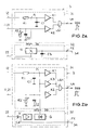
- FIG. 2 shows two exemplary embodiments of the stop signal generator stage 3 shown.
- the stop signal generator stage 3 consists of the logic circuit 31 and the frequency circuit 32 designed as an AM frequency discriminator circuit.
- the logic circuit 31 contains a first comparator K1, a second comparator K2, an AND circuit LG1, a first RC element (capacitor C1 , Resistor R1) and a second RC element (capacitor C2, resistor R2).
- the first comparator K1 is designed as a window comparator which, as frequency information (frequency signal), the zero crossing of the FM discriminator via the connecting line 12 (FM operation) and the zero crossing of the AM frequency discriminator circuit 32 (AM frequency signal AFS) via the connecting line 35 (AM Operation) registered (the node P1 of the logic circuit 31 is supplied with a voltage signal via the connecting line 12 and a current signal via the connecting line 35 as the AM frequency signal AFS).
- the first RC element resistor R1, capacitor C1 is used in both operating modes (AM mode, FM mode) for (low-frequency) smoothing of the respective frequency signal.
- the second comparator K2 is designed as a threshold value comparator, which evaluates the field strength signal present on the connecting line 11, 21 as field strength information: at the output of the second comparator K2, a truth signal is then output to the AND circuit LG1 when the field strength signal exceeds a predetermined threshold value.
- the logic circuit 31 then generates a search stop signal SSS at the output LA when the two inputs of the AND circuit LG1 simultaneously receive truth signals (for example “high” signals) from the outputs of the two comparators K1 and K2.
- the second RC element resistor R2, capacitor C2 serves on the one hand for (low-frequency) smoothing of the field strength signal and on the other hand via the value of the (variable) resistor R2 for influencing the response threshold of the transmitter search stop with regard to the reception field strength, whereby for AM operation and FM Operation the value of resistor R2 (and consequently the response threshold) can be dimensioned differently.
- the AM frequency signal AFS (discriminator signal) for the AM station search is generated by means of the AM frequency discriminator circuit 32.
- a product detector from the multiplier 11, the coupling capacitor C3 and the resonance circuit effective at the frequency input FE with the frequency-determining ceramic resonator C R is used.
- the AM IF signal is fed from the AM reception stage 2 to the AM frequency discriminator circuit 32 via the connecting line 22.
- the ceramic resonator C R is tuned, for example, to the target frequency of the AM intermediate frequency (455 kHz) by means of the pulling capacitor C V.
- the stop signal generator stage 3 consists of the logic circuit 31 and the frequency circuit 32 designed as a selection circuit.
- the logic circuit 31 there is an additional comparator K3 designed as a threshold value comparator for evaluating the signal generated by the selection circuit 32 compared to the logic circuit described with reference to FIG. 2a intended;
- the threshold value comparator K3 which is only effective in AM operation (the first comparator K1 is then ineffective), then supplies a truth signal to the AND circuit LG1 when the AM frequency signal AFS (current signal) emitted by the selection circuit 32 via the connecting line 35 has a specific threshold value exceeds.
- the logic circuit 31 then generates a search stop signal SSS at the output LA when the two inputs of the AND circuit LG1 simultaneously receive truth signals (for example “high” signals) from the outputs of the two comparators K1 and K2 (FM operation) or of the two comparators K2 and K3 (AM operation) received.
- the selection circuit 32 comprising the coupling capacitor C4, the amplifier V and the rectifier G, a frequency signal which is narrowband compared to the bandwidth of the AM IF signal is generated.
- the AM IF signal is fed via the connecting line 22 to the input of the selection circuit and, via the coupling capacitor C4, to the (parallel) resonance circuit consisting of ceramic resonator C R and pulling capacitor C V effective at frequency input FE (in this case it serves to balance the parallel resonance to the band center frequency) and selected; the selected frequency signal is amplified by means of the amplifier V and rectified in the rectifier G and made available to the logic circuit 31 as the AM frequency signal AFS via the connecting line 35.
- the series resonance of the frequency-determining ceramic resonator C R can be used to generate the AM frequency signal AFS (current signal) by using a pulling capacitor to produce a series resonance at the desired frequency of the AM IF.
- AFS current signal
- the otherwise existing signal negative feedback for the signal frequencies around the series resonance is suppressed, as a result of which the gain of the amplifier V has a pronounced maximum at the frequency of the series resonance.
- a second pulling capacitor arranged in series with the ceramic resonator C R or the first pulling capacitor can be used if a further (non-tunable) capacitor is connected in series with the ceramic resonator.
Landscapes
- Engineering & Computer Science (AREA)
- Power Engineering (AREA)
- Circuits Of Receivers In General (AREA)
Description
Im FM-Betrieb wird der (FM-) Sendersuchlauf in einfachen Rundfunkempfängern allein anhand der Feldstärkeinformation der FM-Empfangsstufe bewertet: wenn auf einer Frequenz das Feldstärkesignal des Empfangssignals einen vorgegebenen Schwellwert-Pegel überschreitet, wird von einer Stopsignalgeneratorstufe ein Sendersuchlaufstopsignal erzeugt, das einer PLL-Schaltung zugeführt wird und den Sendersuchlauf unterbricht (Sendersuchlaufstop); aufgrund geringer Frequenzabstände der verschiedenen Sender und nicht ausreichender Nachbarkanaltrennung im Rundfunkempfänger wird jedoch häufig ein Sendersuchlaufstop ausgelöst, ohne daß die richtige Frequenz getroffen wurde (ein sog. "Fehlstop"). Daher wird oftmals zusätzlich zum Feldstärkesignal eine Diskriminatorspannung als Spannung eines für die FM-Empfangsfunktion benötigten Frequenzdiskriminators (Frequenzdemodulators) der FM-Empfangsstufe (beispielsweise der FM-Demodulator der FM-Empfangsstufe) bewertet, wobei die Feldstärkeinformation und die frequenzabhängige Spannungsinformation des Frequenzdiskriminators (Frequenzinformation) der FM-Empfangsstufe logisch miteinander verknüpft werden: erst wenn sowohl ein adäquates Feldstärkesignal als auch eine adäquate mittlere Diskriminatorspannung für die "Soll-Zwischenfrequenz" des empfangenen Signals vorliegen, wird ein Sendersuchlaufstopsignal erzeugt und der Sendersuchlaufstop ausgelöst. Eine weitere Möglichkeit besteht darin, den Sendersuchlauf digital mittels ZF-Zählung zu bewerten: die Zwischenfrequenz auf der ZF-Ebene wird mit Hilfe eines Frequenzzählers im ZF-Verstärker (dem sog. "ZF-Zähler") digital bestimmt und ausgewertet; beim Erreichen der Zwischenfrequenz wird ein sendersuchlaufstopsignal erzeugt und der Sendersuchlaufstop ausgelöst. Obwohl die Zwischenfrequenz quarzgenau und damit temperaturunabhängig exakt bestimmt werden kann, wird wegen des erhöhten Hardware-Aufwands, der EMV-Probleme beim Betrieb des Frequenzzählers und der Möglichkeit von Fehlstops zwischen zwei gleich starken Sendern, der Sendersuchlauf im FM-Bereich in der Regel über die gemeinsame Bewertung der bereits von anderen Schaltungskomponenten der FM-Empfangsstufe gelieferten Informationen Feldstärkesignal und Diskriminatorspannung durchgeführt.
im AM-Betrieb wird für den (AM-) Sendersuchlauf üblicherweise nur die Feldstärkeinformation bewertet, da in der AM-Empfangsstufe ein Frequenzdiskriminator für die AM-Empfangsfunktion nicht benötigt wird und somit auch keine Information über eine Diskriminatorspannng vorliegt. um eine vernünftige Generierung des AM-Sendersuchlaufstops zu ermöglichen, muß auch im AM-Betrieb zusätzlich eine frequenzabhängige Spannungsinformation herangezogen werden; hierzu müssen zusätzliche Schaltungselemente vorgesehen werden, die Informationen über die Zwischenfrequenz (ZF) liefern:
- beispielsweise kann im AM-Betrieb für die Generierung der frequenzabhängigen Spannungsinformation bzw. des Frequenzsignals (ähnlich wie im FM-Betrieb) ein Frequenzdiskriminator eingesetzt werden, wobei hierfür beispielsweise der FM-ZF-Verstärker und FM-Diskriminator der FM-Empfangsstufe verwendet wird. In diesem Falle wird das AM-ZF-Signal von der AM-Empfangsstufe in den FM-ZF-Verstärker der FM-Empfangsstufe eingekoppelt, verstärkt und begrenzt. Das Frequenzsignal wird dabei üblicherweise in einem Produktdetektor erzeugt, der aus einem Multiplizierer, einem Phasenkreis für die FM-ZF und einem Phasenkreis für die AM-ZF besteht (der Phasenkreis für die AM-ZF kann beispielsweise ein LC-Schwingkreis sein, der in Reihe zum Phasenkreis für die FM-ZF geschaltet ist). In der Stopsignalgeneratorstufe wird - nach Glättung von Feldstärkesignal und Frequenzsignal - mittels logischer Verknüpfung das Sendersuchlaufstopsignal generiert. Als Feldstärkesignal kann hierbei auch das bei der Verstärkungsregelung im AM-Betrieb anfallende Regelsignal ausgewertet werden.
- bei einer anderen Möglichkeit wird das AM-ZF-Signal in einer Selektionsschaltung einer zusätzlichen, schmalbandigen Selektion unterzogen, wobei die Resonanzspitze innerhalb des ZF-Durchlaßbereiches liegt; am Ausgang der Selektionsschaltung entsteht während des Sendersuchlaufs ein Gleichsignal, das in der Stopsignalgeneratorstufe ausgewertet wird. Beim Überschreiten eines Schwellwerts wird durch logische Verknüpfung mit dem Feldstärkesignal ggf. ein Sendersuchlaufstopsignal erzeugt. um eine schmalbandige Selektion zu erreichen, werden in der Selektionsschaltung üblicherweise Keramikresonatoren als frequenzbestimmende Bauelemente eingesetzt, da diese eine hohe Resonanzgüte aufweisen.
Beim AM-Sendersuchlauf wird der Keramikresonator (ggf. über das beispielsweise als elektronischer Umschalter ausgebildete Schaltelement) mit der Stopsignalgeneratorstufe verbunden und liefert die Frequenzinformation für die Frequenzschaltung der Stopsignalgeneratorstufe: der Keramikresonator kann somit beispielsweise als frequenzbestimmendes Bauelement zur Generierung der Frequenzinformation in einer als (AM-ZF-) Frequenzdiskriminatorschaltung ausgebildeten Frequenzschaltung oder beispielsweise als Selektionselement in einer als (AM-ZF-) Selektionsschaltung ausgebildeten Frequenzschaltung wirksam werden. Zur Einstellung der jeweils für die korrekte Funktion des AM-Sendersuchlaufs erforderlichen Resonanzfrequenz (beispielsweise 455 kHz als AM-ZF) kann ein Ziehkondensator vorgesehen werden, der dem Keramikresonator parallelgeschaltet ist bzw. über das schaltelement parallelgeschaltet werden kann und mit diesem einen Resonanzkreis bildet. Die Kapazität des Ziehkondensators kann mechanisch (Trimmkondensatoren) oder elektronisch eingestellt bzw. verändert werden. Bei elektronisch einstellbarem Ziehkondensator (beispielsweise eine Varaktordiode, deren Kapazitätswert über eine variable Gleichspannung gesteuert wird) kann der Abgleich der Parallelresonanz bzw. der Serienresonanz bezüglich des Frequenzeingangs der Frequenzschaltung automatisch im Produktionsprozeß durchgeführt werden; als Kriterium für den richtigen Abgleich kann beispielsweise die Generierung des Sendersuchlaufstopsignals beim Einspeisen eines AM-ZF-Signals mit der Sollfrequenz in die AM-Empfangsstufe herangezogen werden. Durch eine angemessene Vorgabe der Frequenztoleranz des Keramikresonators in Verbindung mit einer "angepaßten" (reduzierten) Resonanzschärfe des am Frequenzeingang der Frequenzschaltung wirksamen Resonanzkreises kann eine ausreichende Zuverlässigkeit bei der Generierung des Sendersuchlaufstopsignals ohne zusätzlichen Abgleichvorgang erreicht werden. Die Parallelresonanz- bzw. Serienresonanzfrequenz des Resonanzkreises aus Keramikresonator und Ziehkondensator kann mittels eines dem Steueranschluß des Ziehkondensators zugeführten (einstellbaren) Gleichspannungssignals oder (einstellbaren) Gleichstromsignals erfolgen, durch das der Kapazitätswert des Ziehkondensators variiert wird.
Claims (15)
- Schaltungsanordnung eines Rundfunkempfängers mit:dadurch gekennzeichnet:einer FM-Empfangsstufe (1) für den FM-Betrieb,einer AM-Empfangsstufe (2) für den AM-Betrieb,einer Stopsignalgeneratorstufe (3) zur Generierung eines Sendersuchlaufstopsignals (SSS) für den Sendersuchlauf mittels eines Feldstärkesignals (FSS, RS) und eines Frequenzsignals (FS),einer Multiplex-Stereodekoderstufe (4) mit einem mittels eines Keramikresonators (CR) einer bestimmten Resonanzfrequenz angesteuerten VCO (41),die Stopsignalgeneratorstufe (3) weist eine Frequenzschaltung (32) mit einem Frequenzeingang (FE) zur Erzeugung des Frequenzsignals (AFS) für den AM-Sendersuchlauf und eine Logikschaltung (31) zur Generierung des Sendersuchlaufstopsignals (SSS) auf,der Frequenzeingang (FE) der Frequenzschaltung (32) der Stopsignalgeneratorstufe (3) ist im AM-Betrieb zur Generierung des Sendersuchlaufstopsignals (SSS) mit einem Resonanzkreis aus einem Ziehkondensator (CV) mit variierbarer Kapazität und dem eine Resonanzfrequenz von 456 kHz aufweisenden Keramikresonator (CR) verbunden.
- Schaltungsanordnung nach Anspruch 1, dadurch gekennzeichnet, daß der Frequenzeingang (FE) der Frequenzschaltung (32) der Stopsignalgeneratorstufe (3) mit dem Ziehkondensator (CV) direkt und mit dem Keramikresonator (CR) über ein Schaltelement (SE) mit zwei Schaltanschlüssen verbunden ist.
- Schaltungsanordnung nach Anspruch 1, dadurch gekennzeichnet, daß der Frequenzeingang (FE) der Frequenzumschaltung (32) der Stopsignalgeneratorstufe (3) direkt mit dem Keramikresonator (CR) und dem als Ziehkondensator für den VCO (41) der MPX-Stereodekoderstufe (4) eingesetzten Ziehkondensator (CV) verbunden ist.
- Schaltungsanordnung nach einem der Ansprüche 1 bis 3, dadurch gekennzeichnet, daß die Frequenzschaltung (32) der Stopsignalgeneratorstufe (3) als AM-Frequenzdiskriminatorschaltung ausgebildet ist.
- Schaltungsanordnung nach einem der Ansprüche 1 bis 3, dadurch gekennzeichnet, daß die Frequenzschaltung (32) der Stopsignalgeneratorstufe (3) als Selektionsschaltung ausgebildet ist.
- Schaltungsanordnung nach Anspruch 5, dadurch gekennzeichnet, daß im Resonanzkreis der Keramikresonator (CR) und der Ziehkondensator (CV) parallelgeschaltet sind, so daß zur Erzeugung des Frequenzsignals (AFS) für den AM-Sendersuchlauf die Parallelresonanz von Keramikresonator (CR) und Ziehkondensator (CV) bestimmend ist.
- Schaltungsanordnung nach Anspruch 5, dadurch gekennzeichnet, daß im Resonanzkreis der Keramikresonator (CR) und der Ziehkondensator (CV) in Serie geschaltet sind, so daß zur Erzeugung des Frequenzsignals (AFS) für den AM-Sendersuchlauf die Serienresonanz von Keramikresonator (CR) und Ziehkondensator (CV) bestimmend ist.
- Schaltungsanordnung nach einem der Ansprüche 1 bis 7, dadurch gekennzeichnet, daß der Ziehkondensator (CV) als Trimmkondensator ausgebildet ist.
- Schaltungsanordnung nach einem der Ansprüche 1 bis 7, dadurch gekennzeichnet, daß der Ziehkondensator (CV) als elektronisches Bauelement oder elektronische Schaltung ausgebildet ist.
- Schaltungsanordnung nach Anspruch 9, dadurch gekennzeichnet, daß der Ziehkondensator (CV) als Varaktordiode ausgebildet ist.
- Schaltungsanordnung nach einem der Ansprüche 1 bis 10, dadurch gekennzeichnet, daß der Steueranschluß des Ziehkondensators (CV) mit einer Gleichspannungsquelle oder Gleichstromquelle verbunden ist, so daß der Frequenzabgleich bei der Generierung des Frequenzsignals (AFS) für den AM-Sendersuchlauf durch ein am Steueranschluß des Ziehkondensators (CV) angelegtes Gleichspannungssignal (USt) oder Gleichstromsignal erfolgt.
- Schaltungsanordnung nach einem der Ansprüche 1 bis 11, dadurch gekennzeichnet, daß die Frequenzschaltung (32) der Stopsignalgeneratorstufe (3) als Frequenzsignal (AFS) ein Stromsignal erzeugt, mit dem die Logikschaltung (31) der Stopsignalgeneratorstufe (3) über eine verbindungsleitung (35) beaufschlagbar ist.
- Schaltungsanordnung nach Anspruch 1 und 12, dadurch gekennzeichnet, daß die Logikschaltung (31) der Stopsignalgeneratorstufe (3) zur niederfrequenten Glättung des Frequenzsignals (AFS) für den AM-Sendersuchlauf und des Frequenzsignals (FFS) für den FM-Sendersuchlauf ein erstes RC-Glied (R1, C1) aufweist.
- Schaltungsanordnung nach einem der Ansprüche 1, 12 oder 13, dadurch gekennzeichnet, daß das Feldstärkesignal (RS) für den AM-Sendersuchlauf und das Feldstärkesignal (FSS) für den FM-Sendersuchlauf jeweils als Stromsignal ausgebildet ist, und daß die Logikschaltung (31) der Stopsignalgeneratorstufe (3) zur niederfrequenten Glättung der Feldstärkesignale (FSS, RS) ein zweites RC-Glied (R2, C2) aufweist.
- Schaltungsanordnung nach Anspruch 1 oder 14, dadurch gekennzeichnet, daß die Logikschaltung (31) zur Variation der Ansprechschwelle der Feldstärkesignale (FSS, RS) bei der Generierung des Sendersuchlaufstopsignals (SSS) einen einstellbaren Widerstand (R2) aufweist.
Applications Claiming Priority (2)
| Application Number | Priority Date | Filing Date | Title |
|---|---|---|---|
| DE19603721A DE19603721A1 (de) | 1996-02-02 | 1996-02-02 | Schaltungsanordnung eines Rundfunkempfängers |
| DE19603721 | 1996-02-02 |
Publications (2)
| Publication Number | Publication Date |
|---|---|
| EP0788226A1 EP0788226A1 (de) | 1997-08-06 |
| EP0788226B1 true EP0788226B1 (de) | 2000-07-12 |
Family
ID=7784321
Family Applications (1)
| Application Number | Title | Priority Date | Filing Date |
|---|---|---|---|
| EP97100901A Expired - Lifetime EP0788226B1 (de) | 1996-02-02 | 1997-01-22 | Schaltungsanordnung eines Rundfunkempfängers |
Country Status (2)
| Country | Link |
|---|---|
| EP (1) | EP0788226B1 (de) |
| DE (2) | DE19603721A1 (de) |
Families Citing this family (1)
| Publication number | Priority date | Publication date | Assignee | Title |
|---|---|---|---|---|
| DE50003128D1 (de) | 1999-06-23 | 2003-09-04 | Infineon Technologies Ag | Integrierte schaltung zur detektion eines empfangssignals sowie schaltungsanordnung |
Family Cites Families (5)
| Publication number | Priority date | Publication date | Assignee | Title |
|---|---|---|---|---|
| JPS5922409B2 (ja) * | 1979-02-26 | 1984-05-26 | シャープ株式会社 | 電子同調方式のラジオ受信機 |
| JPS55130220A (en) * | 1979-03-30 | 1980-10-08 | Sharp Corp | Stop signal device for automatic tuning of broadcast receiver |
| US4580285A (en) * | 1983-09-07 | 1986-04-01 | Sprague Electric Company | Scanning AM radio with discriminator-driven-scan-stop-circuit |
| US4509204A (en) * | 1983-09-23 | 1985-04-02 | National Semiconductor Corporation | AM Radio stop detector |
| JPS6178230A (ja) * | 1984-09-26 | 1986-04-21 | Nec Corp | 集積化am/fm切換回路 |
-
1996
- 1996-02-02 DE DE19603721A patent/DE19603721A1/de not_active Withdrawn
-
1997
- 1997-01-22 DE DE59701984T patent/DE59701984D1/de not_active Expired - Fee Related
- 1997-01-22 EP EP97100901A patent/EP0788226B1/de not_active Expired - Lifetime
Also Published As
| Publication number | Publication date |
|---|---|
| EP0788226A1 (de) | 1997-08-06 |
| DE19603721A1 (de) | 1997-08-07 |
| DE59701984D1 (de) | 2000-08-17 |
Similar Documents
| Publication | Publication Date | Title |
|---|---|---|
| EP0561117B1 (de) | Schaltungsanordnung zur Nachbarkanalerkennung und -unterdrückung in einem Rundfunkempfänger | |
| DE19621076C2 (de) | Vorrichtung und Verfahren zum kontaktlosen Übertragen von Energie oder Daten | |
| DE69618524T2 (de) | Empfänger und Abstimmschaltung mit einem Frequenzsynthetisierer dafür | |
| EP0595314B1 (de) | Verfahren zur Abstimmung eines Rundfunkempfängers | |
| DE3627226A1 (de) | Sicherheitssystem | |
| DE2910039C2 (de) | FM-Empfänger mit Störimpulsdetektor | |
| DE2428880A1 (de) | Fm-am-rundfunkempfaenger | |
| DE2909520C3 (de) | Schaltungsanordnung zur Dämpfung von Störgeräuschen | |
| DE3046540A1 (de) | Phasenregelkreis | |
| DE69221850T2 (de) | Kombinierter am-fm stereo-empfänger | |
| EP0017130B1 (de) | Empfänger für hochfrequente elektromagnetische Schwingungen mit einer Frequenznachregelung | |
| DE60121247T2 (de) | Empfänger mit einem Synthesizer | |
| EP0148389B1 (de) | Abstimmsystem für einen Fernsehempfänger | |
| DE3213870C2 (de) | Automatische Sendersuchlaufvorrichtung für einen FM-Tuner | |
| DE69328484T2 (de) | Regelkreis mit negativer Rückkopplung mit einer gemeinsamen Leitung für Eingang und Ausgang | |
| DD286072A5 (de) | Satelliten-rundfunkempfaenger | |
| EP0578007B1 (de) | Schaltungsanordnung zur Erkennung und Unterdrückung von Nachbarkanalstörungen | |
| EP0788226A1 (de) | Schaltungsanordnung eines Rundfunkempfängers | |
| DE19904604A1 (de) | Verfahren zum Abgleichen eines Bandpasses und Schaltungsanordnung zur Durchführung des Verfahrens | |
| DE4017418A1 (de) | Empfaenger | |
| DE2909997A1 (de) | Vhf-tuner | |
| EP1128552A1 (de) | Schaltungsanordnung zur Filterung eines Hochfequenzsignals | |
| EP0342740B1 (de) | Schaltungsanordnung zum Synchronisieren eines in der Frequenz steuerbaren Oszillators | |
| EP0620643B1 (de) | Schaltungsanordnung zur Erzeugung eines Stopp-Signals für einen Sendersuchlauf | |
| DE3346981A1 (de) | Ton-zf-verstaerker fuer einen mehrnormen-fernsprechempfaenger |
Legal Events
| Date | Code | Title | Description |
|---|---|---|---|
| PUAI | Public reference made under article 153(3) epc to a published international application that has entered the european phase |
Free format text: ORIGINAL CODE: 0009012 |
|
| AK | Designated contracting states |
Kind code of ref document: A1 Designated state(s): DE FR GB IT |
|
| 17P | Request for examination filed |
Effective date: 19970702 |
|
| RAP1 | Party data changed (applicant data changed or rights of an application transferred) |
Owner name: TEMIC SEMICONDUCTOR GMBH |
|
| GRAG | Despatch of communication of intention to grant |
Free format text: ORIGINAL CODE: EPIDOS AGRA |
|
| GRAG | Despatch of communication of intention to grant |
Free format text: ORIGINAL CODE: EPIDOS AGRA |
|
| GRAH | Despatch of communication of intention to grant a patent |
Free format text: ORIGINAL CODE: EPIDOS IGRA |
|
| 17Q | First examination report despatched |
Effective date: 19991207 |
|
| GRAH | Despatch of communication of intention to grant a patent |
Free format text: ORIGINAL CODE: EPIDOS IGRA |
|
| ITF | It: translation for a ep patent filed | ||
| GRAA | (expected) grant |
Free format text: ORIGINAL CODE: 0009210 |
|
| AK | Designated contracting states |
Kind code of ref document: B1 Designated state(s): DE FR GB IT |
|
| REF | Corresponds to: |
Ref document number: 59701984 Country of ref document: DE Date of ref document: 20000817 |
|
| GBT | Gb: translation of ep patent filed (gb section 77(6)(a)/1977) |
Effective date: 20000907 |
|
| ET | Fr: translation filed | ||
| RAP2 | Party data changed (patent owner data changed or rights of a patent transferred) |
Owner name: ATMEL GERMANY GMBH |
|
| PLBE | No opposition filed within time limit |
Free format text: ORIGINAL CODE: 0009261 |
|
| STAA | Information on the status of an ep patent application or granted ep patent |
Free format text: STATUS: NO OPPOSITION FILED WITHIN TIME LIMIT |
|
| 26N | No opposition filed | ||
| REG | Reference to a national code |
Ref country code: GB Ref legal event code: IF02 |
|
| GBPC | Gb: european patent ceased through non-payment of renewal fee |
Effective date: 20070122 |
|
| PG25 | Lapsed in a contracting state [announced via postgrant information from national office to epo] |
Ref country code: GB Free format text: LAPSE BECAUSE OF NON-PAYMENT OF DUE FEES Effective date: 20070122 |
|
| PGFP | Annual fee paid to national office [announced via postgrant information from national office to epo] |
Ref country code: IT Payment date: 20080125 Year of fee payment: 12 |
|
| PGFP | Annual fee paid to national office [announced via postgrant information from national office to epo] |
Ref country code: FR Payment date: 20080111 Year of fee payment: 12 |
|
| PGFP | Annual fee paid to national office [announced via postgrant information from national office to epo] |
Ref country code: GB Payment date: 20060120 Year of fee payment: 10 |
|
| PGFP | Annual fee paid to national office [announced via postgrant information from national office to epo] |
Ref country code: DE Payment date: 20090122 Year of fee payment: 13 |
|
| REG | Reference to a national code |
Ref country code: FR Ref legal event code: ST Effective date: 20091030 |
|
| PG25 | Lapsed in a contracting state [announced via postgrant information from national office to epo] |
Ref country code: FR Free format text: LAPSE BECAUSE OF NON-PAYMENT OF DUE FEES Effective date: 20090202 |
|
| PG25 | Lapsed in a contracting state [announced via postgrant information from national office to epo] |
Ref country code: DE Free format text: LAPSE BECAUSE OF NON-PAYMENT OF DUE FEES Effective date: 20100803 |
|
| PG25 | Lapsed in a contracting state [announced via postgrant information from national office to epo] |
Ref country code: IT Free format text: LAPSE BECAUSE OF NON-PAYMENT OF DUE FEES Effective date: 20090122 |