EP0787891A2 - Production d'énergie mécanique par l'expansion d'un liquide en vapeur - Google Patents
Production d'énergie mécanique par l'expansion d'un liquide en vapeur Download PDFInfo
- Publication number
- EP0787891A2 EP0787891A2 EP96309518A EP96309518A EP0787891A2 EP 0787891 A2 EP0787891 A2 EP 0787891A2 EP 96309518 A EP96309518 A EP 96309518A EP 96309518 A EP96309518 A EP 96309518A EP 0787891 A2 EP0787891 A2 EP 0787891A2
- Authority
- EP
- European Patent Office
- Prior art keywords
- expansion
- pressure
- vapour
- built
- ratio
- Prior art date
- Legal status (The legal status is an assumption and is not a legal conclusion. Google has not performed a legal analysis and makes no representation as to the accuracy of the status listed.)
- Granted
Links
Images


Classifications
-
- F—MECHANICAL ENGINEERING; LIGHTING; HEATING; WEAPONS; BLASTING
- F01—MACHINES OR ENGINES IN GENERAL; ENGINE PLANTS IN GENERAL; STEAM ENGINES
- F01K—STEAM ENGINE PLANTS; STEAM ACCUMULATORS; ENGINE PLANTS NOT OTHERWISE PROVIDED FOR; ENGINES USING SPECIAL WORKING FLUIDS OR CYCLES
- F01K21/00—Steam engine plants not otherwise provided for
- F01K21/005—Steam engine plants not otherwise provided for using mixtures of liquid and steam or evaporation of a liquid by expansion
-
- F—MECHANICAL ENGINEERING; LIGHTING; HEATING; WEAPONS; BLASTING
- F01—MACHINES OR ENGINES IN GENERAL; ENGINE PLANTS IN GENERAL; STEAM ENGINES
- F01K—STEAM ENGINE PLANTS; STEAM ACCUMULATORS; ENGINE PLANTS NOT OTHERWISE PROVIDED FOR; ENGINES USING SPECIAL WORKING FLUIDS OR CYCLES
- F01K25/00—Plants or engines characterised by use of special working fluids, not otherwise provided for; Plants operating in closed cycles and not otherwise provided for
- F01K25/04—Plants or engines characterised by use of special working fluids, not otherwise provided for; Plants operating in closed cycles and not otherwise provided for the fluid being in different phases, e.g. foamed
-
- F—MECHANICAL ENGINEERING; LIGHTING; HEATING; WEAPONS; BLASTING
- F25—REFRIGERATION OR COOLING; COMBINED HEATING AND REFRIGERATION SYSTEMS; HEAT PUMP SYSTEMS; MANUFACTURE OR STORAGE OF ICE; LIQUEFACTION SOLIDIFICATION OF GASES
- F25B—REFRIGERATION MACHINES, PLANTS OR SYSTEMS; COMBINED HEATING AND REFRIGERATION SYSTEMS; HEAT PUMP SYSTEMS
- F25B1/00—Compression machines, plants or systems with non-reversible cycle
- F25B1/10—Compression machines, plants or systems with non-reversible cycle with multi-stage compression
-
- F—MECHANICAL ENGINEERING; LIGHTING; HEATING; WEAPONS; BLASTING
- F25—REFRIGERATION OR COOLING; COMBINED HEATING AND REFRIGERATION SYSTEMS; HEAT PUMP SYSTEMS; MANUFACTURE OR STORAGE OF ICE; LIQUEFACTION SOLIDIFICATION OF GASES
- F25B—REFRIGERATION MACHINES, PLANTS OR SYSTEMS; COMBINED HEATING AND REFRIGERATION SYSTEMS; HEAT PUMP SYSTEMS
- F25B11/00—Compression machines, plants or systems, using turbines, e.g. gas turbines
- F25B11/02—Compression machines, plants or systems, using turbines, e.g. gas turbines as expanders
-
- F—MECHANICAL ENGINEERING; LIGHTING; HEATING; WEAPONS; BLASTING
- F25—REFRIGERATION OR COOLING; COMBINED HEATING AND REFRIGERATION SYSTEMS; HEAT PUMP SYSTEMS; MANUFACTURE OR STORAGE OF ICE; LIQUEFACTION SOLIDIFICATION OF GASES
- F25B—REFRIGERATION MACHINES, PLANTS OR SYSTEMS; COMBINED HEATING AND REFRIGERATION SYSTEMS; HEAT PUMP SYSTEMS
- F25B2400/00—General features or devices for refrigeration machines, plants or systems, combined heating and refrigeration systems or heat-pump systems, i.e. not limited to a particular subgroup of F25B
- F25B2400/07—Details of compressors or related parts
- F25B2400/075—Details of compressors or related parts with parallel compressors
-
- F—MECHANICAL ENGINEERING; LIGHTING; HEATING; WEAPONS; BLASTING
- F25—REFRIGERATION OR COOLING; COMBINED HEATING AND REFRIGERATION SYSTEMS; HEAT PUMP SYSTEMS; MANUFACTURE OR STORAGE OF ICE; LIQUEFACTION SOLIDIFICATION OF GASES
- F25B—REFRIGERATION MACHINES, PLANTS OR SYSTEMS; COMBINED HEATING AND REFRIGERATION SYSTEMS; HEAT PUMP SYSTEMS
- F25B2400/00—General features or devices for refrigeration machines, plants or systems, combined heating and refrigeration systems or heat-pump systems, i.e. not limited to a particular subgroup of F25B
- F25B2400/13—Economisers
-
- F—MECHANICAL ENGINEERING; LIGHTING; HEATING; WEAPONS; BLASTING
- F25—REFRIGERATION OR COOLING; COMBINED HEATING AND REFRIGERATION SYSTEMS; HEAT PUMP SYSTEMS; MANUFACTURE OR STORAGE OF ICE; LIQUEFACTION SOLIDIFICATION OF GASES
- F25B—REFRIGERATION MACHINES, PLANTS OR SYSTEMS; COMBINED HEATING AND REFRIGERATION SYSTEMS; HEAT PUMP SYSTEMS
- F25B2400/00—General features or devices for refrigeration machines, plants or systems, combined heating and refrigeration systems or heat-pump systems, i.e. not limited to a particular subgroup of F25B
- F25B2400/23—Separators
Definitions
- This invention relates to a method and apparatus for deriving mechanical power from expansion of a liquid or wet vapour into vapour by means of positive displacement machinery.
- positive displacement machinery used herein refers to a machine or a series of two or more machines in which, or in each of which, at least one chamber for containing a working fluid cyclically undergoes the following steps: to receive a charge of working fluid, to be closed, to have its volume increased or decreased, to be opened for release of the charge of working liquid and thereafter to have its volume decreased or increased respectively to the value obtaining at the start of the cycle.
- the built-in volume ratio as used herein in respect of a positive displacement machine used as an expander is the ratio of the maximum volume of a working chamber, just prior to its opening, to the volume thereof at the instant the chamber is closed.
- the built-in volume ratio of the machinery is the product of the built-in volume ratios of the individual machines.
- apparatus for deriving mechanical power from expansion of a working fluid, other than water, from a liquid state at a first pressure to vapour at a second, lower pressure
- the apparatus including positive displacement machinery, wherein the in-built volumetric expansion ratio of the positive displacement machinery is between 10 and 50% of the overall volume ratio of expansion experienced by the fluid in the pressure reduction between the entry and the exit of the machinery.
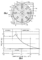
- Figure 1 shows diagrammatically a conventional vane-type compressor as one example of a positive displacement machine.
- Other examples are Lysholm screw machines mentioned above, single screw compressors, constrained-vane compressors, scroll-type compressors and reciprocatory piston and cylinder machines.
- the compressor shown has a stator housing 1 with a cylindrical interior 2 having an axis 3, a smaller port 4 forming the compressor outlet and a larger port 5 forming the inlet.
- a cylindrical rotor 6 of smaller diameter than the interior 2 is mounted for rotation therein about an axis 7 parallel to, but spaced from, the axis 3.
- Vanes 8 are slidable in equispaced pockets 9 in the rotor and as the latter rotates are thrown outwards to make sealing contact with the inner wall of the housing and thus divide the spaced between the rotor 6 and housing 1 into a set of working chambers 10a-10h, the volume of each of which varies from a minimum between positions 10a and 10b to a maximum between positions 10e and 10f.
- the rotor When used as a compressor, the rotor is driven in the direction of the arrow 11.
- the port 4 forms the inlet and the port 5 the outlet and the rotor is caused to rotate in the opposite direction.
- the mass flow rate through the machine is largely determined by the swept volume of the machine.
- the true induced volume is slightly less than the swept value due to backward leakage of fluid between the vanes, rotors or piston and the casing into the filling volume which is induced by the pressure gradient created by the compression process. This difference is expressed as a volumetric efficiency or ratio of volume of fluid induced to the swept volume in the machine during the filling process. In screw type compressors, where the clearance volume is negligible, this may be of the order of 95 %.
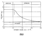
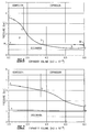
- the built in volume ratio may be selected approximately as the value required to raise the pressure from suction to discharge values according to the pressure-volume relationship appropriate to the compression process assumed i.e with or without liquid injection or external heat transfer. If the assumed value is incorrect, there will be either over pressurisation of the fluid, as shown in Fig. 3, or under pressurisation, as shown in Fig. 4, at the position (R) in the compression process where the discharge process commences. In both cases, the effects on the compressor performance and efficiency will be relatively small.
- the filling process TU is associated with a significant decrease in pressure, and hence, expansion. This is because the fluid accelerated through the inlet port gains momentum. This momentum increase is much larger for wet fluids than for gases because the wet fluids are much denser.
- a further feature which affects the performance of all positive displacement machines, whether operating in expander or compressor mode is internal friction. In all cases efficiency losses associated with it, increase with speed. The best design of expander will therefore involve a compromise between the need for high speed to minimise leakage losses and low speed to minimise friction, a large built in volume ratio to minimise losses due to underexpansion and a small volume ratio to minimise the significance of leakage effects while maximising the mass flow and thereby keeping the size of the expander to a minimum.
- the chiller installation shown in Fig. 8 is conventional in that is comprises a drive motor M the shaft 21 of which drives a compressor for compressing refrigerant vapour from an evaporator 23 which removes heat from a chilling circuit 24.
- the compressor 22 delivers hot compressed vapour to a condenser 25 where it is cooled and condensed into liquid by heat exchange with liquid in a cooling circuit 26.
- the liquid refrigerant would have its pressure reduced by being passed through a throttle valve 27 but instead is here expanded (from liquid to vapour) through a two-phase expander 28 in accordance with the invention.
- the power output of the expander 28 is applied by a shaft 29, either directly or through gearing, to assist the motor M in driving the compressor 22.
- Fig. 9 shows a modification of Fig. 8 in which the two phase expander 28 is arranged to drive a second vapour compressor 30 connected in parallel with the main compressor 22. Both the expander 28 and the second vapour compressor 30 are of the Lysholm twin-screw type.
- Refrigerant 134A as working fluid gives the following results: Overall Expansion Ratio Optimum Built in Expansion Ratio % Ratio Fig.8 13.63 3.20 23 % Fig.9 10.38 2.81 27 %
- positive displacement expanders may be used for the same function in large heat pumps and refrigeration cold stores in identical or related ways such as shown in Fig. 10.
- the main compressor is a two stage compressor which comprises a low pressure compressor 41, driven by a motor M1, the output of which is delivered by a line 42 to the inlet of the second stage, high pressure compressor 43.
- the output from the condenser 25 is passed through a throttle valve 44 for partial expansion into a vapour/liquid separator 45 from which the vapour is delivered through a line 46 to the line 42 supplying the inlet of the high pressure compressor 43.
- the liquid from the separator 45 is delivered to the inlet of the expander 28, the outlet of which is connected to the inlet of the evaporator 23.
- the output shaft 46 of the expander is connected to drive a two stage compressor 47 consisting of two screw compressors in series constructed as a low pressure stage 48 and a high pressure stage 49.
- the low pressure stage receives vapour from the evaporator outlet via a line 50 and the outlet from the high pressure stage 49 is delivered by a line 51 to the inlet of the condenser 25.
- the circuit 26 When used as a heat pump, the circuit 26 is the circuit to be heated by abstraction of heat from the circuit 24.
- Such machines may also be used as the main expander in a system for the recovery of power from low grade heat sources such as geothermal brines, which has been called by the inventors the Trilateral Flash Cycle (TFC) system.
- TFC Trilateral Flash Cycle
- the circuit is shown in fig. 11 and its cycle in Fig. 12.
- temperature changes and hence volume ratios are much larger and hence two or more expansion stages are needed operating in series.
- a typical example of this is, as shown in Fig. 11, the case of a supply of hot brine in the form of saturated liquid at 150°C which is currently being separated from wet steam in a flash steam plant and reinjected into the ground at this temperature.
- the working fluid in the system is n-butane with a temperature at the inlet of the expander 52 of 137°C and a condensing temperature of 35°C in a condenser 53, the condensate from which is pressurised by a feed pump 54 and returned to the heat exchanger 51.
- a large two stage twin screw expander system (driving a generator G), was considered to be the most suitable for this purpose, the main features of which are as follows: Rotor Diam mm Rotor Speed rpm Pressure Drop bar Power Output kW Volume Built in Ratio Overall Adiabatic Effic percent HP Stage: 390 1500 15 828 3.6 4.9 82 LP Stage: 620 1500 12 3042 3.2 7.1 80
Landscapes
- Engineering & Computer Science (AREA)
- Mechanical Engineering (AREA)
- General Engineering & Computer Science (AREA)
- Physics & Mathematics (AREA)
- Thermal Sciences (AREA)
- Chemical & Material Sciences (AREA)
- Combustion & Propulsion (AREA)
- Applications Or Details Of Rotary Compressors (AREA)
- Other Liquid Machine Or Engine Such As Wave Power Use (AREA)
- Engine Equipment That Uses Special Cycles (AREA)
Applications Claiming Priority (2)
| Application Number | Priority Date | Filing Date | Title |
|---|---|---|---|
| GB9602191 | 1996-01-31 | ||
| GB9602191A GB2309748B (en) | 1996-01-31 | 1996-01-31 | Deriving mechanical power by expanding a liquid to its vapour |
Publications (3)
| Publication Number | Publication Date |
|---|---|
| EP0787891A2 true EP0787891A2 (fr) | 1997-08-06 |
| EP0787891A3 EP0787891A3 (fr) | 1999-08-04 |
| EP0787891B1 EP0787891B1 (fr) | 2003-05-28 |
Family
ID=10788062
Family Applications (1)
| Application Number | Title | Priority Date | Filing Date |
|---|---|---|---|
| EP96309518A Expired - Lifetime EP0787891B1 (fr) | 1996-01-31 | 1996-12-27 | Production d'énergie mécanique par l'expansion d'un liquide en vapeur |
Country Status (7)
| Country | Link |
|---|---|
| US (1) | US5833446A (fr) |
| EP (1) | EP0787891B1 (fr) |
| DE (1) | DE69628406T2 (fr) |
| DK (1) | DK0787891T3 (fr) |
| ES (1) | ES2194964T3 (fr) |
| GB (1) | GB2309748B (fr) |
| WO (1) | WO1997028354A1 (fr) |
Cited By (14)
| Publication number | Priority date | Publication date | Assignee | Title |
|---|---|---|---|---|
| EP1067342A3 (fr) * | 1999-07-09 | 2002-02-27 | Carrier Corporation | Détendeur et compresseur comme remplacement d'un robinet détendeur d'écoulement diphasique |
| WO2003098128A1 (fr) * | 2002-05-21 | 2003-11-27 | M-Tec Mittermayr Gmbh | Machine frigorifique |
| EP1376032A2 (fr) * | 2002-06-25 | 2004-01-02 | Carrier Corporation | Régulation de capacité d'un ensemble détendeur-compresseur |
| EP1376030A1 (fr) * | 2002-06-25 | 2004-01-02 | Carrier Corporation | Système de réfrigération avec un compresseur principal et un ensemble détendeur-compresseur à vis |
| WO2005019743A1 (fr) * | 2003-06-16 | 2005-03-03 | Carrier Corporation | Regulation de pression supercritique d'un systeme de compression de vapeur |
| WO2005031123A1 (fr) * | 2003-09-25 | 2005-04-07 | City University | Obtenir de la puissance d'une source thermique a faible temperature |
| EP1586832A1 (fr) * | 2003-01-08 | 2005-10-19 | Daikin Industries, Ltd. | Appareil de refrigeration |
| EP1596140A2 (fr) * | 2004-05-14 | 2005-11-16 | Robert Bosch Gmbh | Dispositif pour l'expansion d'un réfrigérant |
| EP1752615A2 (fr) * | 2005-03-31 | 2007-02-14 | Air Products and Chemicals, Inc. | Procédé une source thermique de faible intensité à l'aide d'une machine à expansion de fluide dense |
| EP2097686A1 (fr) * | 2006-12-26 | 2009-09-09 | Carrier Corporation | Système de réfrigération à base de co2 équipé de compresseurs en tandem, d'un détendeur et d'un économiseur |
| EP2159386A2 (fr) * | 2008-08-14 | 2010-03-03 | Tramontana Technology Group (Holding) GmbH | Système de génération d'énergie thermique et solaire de haute efficacité utilisant un échangeur thermique de haute efficacité et une unité de conversion d'énergie |
| CN103306764A (zh) * | 2013-07-05 | 2013-09-18 | 重庆大学 | 一种带两相膨胀机的Kalina循环系统 |
| CN105986840A (zh) * | 2015-03-23 | 2016-10-05 | 株式会社神户制钢所 | 热回收型发电系统 |
| WO2017021293A1 (fr) * | 2015-07-31 | 2017-02-09 | Bitzer Kühlmaschinenbau Gmbh | Dispositif et procédé permettant la mise en œuvre d'un processus de vaporisation à froid |
Families Citing this family (41)
| Publication number | Priority date | Publication date | Assignee | Title |
|---|---|---|---|---|
| US6427453B1 (en) * | 1998-07-31 | 2002-08-06 | The Texas A&M University System | Vapor-compression evaporative air conditioning systems and components |
| WO2000053926A1 (fr) | 1999-03-05 | 2000-09-14 | Honda Giken Kogyo Kabushiki Kaisha | Machine rotative a fluide, machine a fluide a aubes, et dispositif de recuperation de chaleur de moteur a combustion interne |
| SE9902024D0 (sv) * | 1999-06-02 | 1999-06-02 | Henrik Oehman | Anordning vid en kylanordning med en köldmedieseparator |
| JP2003187694A (ja) * | 2001-12-21 | 2003-07-04 | Dainippon Screen Mfg Co Ltd | 隔壁形成方法、隔壁形成装置およびパネル |
| CN1193200C (zh) * | 2002-12-16 | 2005-03-16 | 西安交通大学 | 一种制冷系统用转子压缩-膨胀机 |
| RU2006114770A (ru) * | 2003-09-29 | 2007-11-10 | Селф Пропеллед Рисерч энд Дивелопмент Спешелистс,эЛэЛСи (US) | Сушильное устройство (варианты), стиральное устройство и сушильная камера (варианты) |
| GB0413442D0 (en) * | 2004-06-16 | 2004-07-21 | Ea Technical Services Ltd | Rolling piston stirling engine |
| US20070065326A1 (en) * | 2005-09-19 | 2007-03-22 | Orsello Robert J | Rotary piston and methods for operating a rotary piston as a pump, compressor and turbine |
| EP2044318A1 (fr) * | 2006-07-26 | 2009-04-08 | Turner, Geoffrey Russell | Systeme d'alimentation en energie |
| US20080163625A1 (en) * | 2007-01-10 | 2008-07-10 | O'brien Kevin M | Apparatus and method for producing sustainable power and heat |
| GB2446457A (en) * | 2007-02-08 | 2008-08-13 | Epicam Ltd | Rotary power generation |
| WO2009101818A1 (fr) * | 2008-02-15 | 2009-08-20 | Panasonic Corporation | Appareil à cycle de réfrigération |
| EP2244037A4 (fr) * | 2008-02-20 | 2012-04-25 | Panasonic Corp | Dispositif de cycle de réfrigération |
| DE102008024116A1 (de) * | 2008-05-17 | 2009-11-19 | Hamm & Dr. Oser GbR (vertretungsberechtiger Gesellschafter: Dr. Erwin Oser, 50670 Köln) | Umwandlung der Druckenergie von Gasen und Dämpfen bei niedrigen Ausgangsdrücken in mechanische Energie |
| JP5628892B2 (ja) | 2009-04-01 | 2014-11-19 | リナム システムズ、リミテッド | 廃熱空調システム |
| US20120017636A1 (en) * | 2009-05-29 | 2012-01-26 | Panasonic Corporation | Refrigeration cycle apparatus |
| WO2010140324A1 (fr) * | 2009-06-02 | 2010-12-09 | 三菱電機株式会社 | Dispositif à cycle de réfrigération |
| NZ599275A (en) * | 2009-09-23 | 2014-07-25 | Bright Energy Storage Technologies Llp | System for underwater compressed fluid energy storage and method of deploying same |
| CN102510985B (zh) * | 2009-09-24 | 2014-08-06 | 三菱电机株式会社 | 冷冻循环装置 |
| US20110175358A1 (en) * | 2010-01-15 | 2011-07-21 | Richard Langson | One and two-stage direct gas and steam screw expander generator system (dsg) |
| US20110271676A1 (en) | 2010-05-04 | 2011-11-10 | Solartrec, Inc. | Heat engine with cascaded cycles |
| JP5484604B2 (ja) * | 2011-02-09 | 2014-05-07 | 三菱電機株式会社 | 冷凍空調装置 |
| US9562444B2 (en) * | 2011-09-30 | 2017-02-07 | Nissan Motor Co., Ltd. | Engine waste-heat utilization device |
| US9476340B2 (en) | 2012-04-16 | 2016-10-25 | GM Global Technology Operations LLC | Vehicle with stirling engine integrated into engine exhaust system |
| DE102012014967A1 (de) * | 2012-07-30 | 2014-01-30 | Isabelle Oelschlägel | D.I.O. -device to intelligente generate own electricity Integrierte Vorrichtung zur Stromgewinnung während des Betriebes einer Wärme- bzw. Kältemaschine. |
| CN102996321A (zh) * | 2012-11-23 | 2013-03-27 | 贾东明 | 一种用于发电的动力循环系统 |
| CN102996192B (zh) * | 2012-12-31 | 2015-01-07 | 西安工业大学 | 高效内循环发动机 |
| EP2937526B1 (fr) * | 2014-04-04 | 2017-03-22 | Panasonic Intellectual Property Management Co., Ltd. | Système combiné de production d'elecricite et de chauffage |
| CN105953454B (zh) * | 2015-04-13 | 2021-04-20 | 李华玉 | 双向热力循环与第一类热驱动压缩式热泵 |
| CN105953453B (zh) * | 2015-04-13 | 2021-04-16 | 李华玉 | 双向热力循环与第一类热驱动压缩式热泵 |
| CN106225282B (zh) * | 2015-12-30 | 2020-05-29 | 李华玉 | 第一类热驱动压缩式热泵 |
| CN106440511B (zh) * | 2015-12-30 | 2020-05-12 | 李华玉 | 第一类热驱动压缩式热泵 |
| CN106225281B (zh) * | 2015-12-30 | 2020-06-16 | 李华玉 | 第一类热驱动压缩式热泵 |
| CN106352578B (zh) * | 2015-12-30 | 2020-04-21 | 李华玉 | 第一类热驱动压缩式热泵 |
| CN106403370B (zh) * | 2015-12-30 | 2020-06-16 | 李华玉 | 第一类热驱动压缩式热泵 |
| CN106403371B (zh) * | 2016-02-05 | 2020-08-21 | 李华玉 | 第一类热驱动压缩式热泵 |
| CN106440510B (zh) * | 2016-02-25 | 2020-05-29 | 李华玉 | 第二类热驱动压缩式热泵 |
| CN106403372B (zh) * | 2016-02-25 | 2020-05-01 | 李华玉 | 第二类热驱动压缩式热泵 |
| CN106225321B (zh) * | 2016-04-17 | 2020-04-21 | 李华玉 | 第二类热驱动压缩式热泵 |
| CN106225284B (zh) * | 2016-04-17 | 2020-04-07 | 李华玉 | 第一类热驱动压缩式热泵 |
| RU168561U1 (ru) * | 2016-04-18 | 2017-02-08 | Федеральное государственное бюджетное образовательное учреждение высшего профессионального образования "Казанский государственный энергетический университет" (ФГБОУ ВПО "КГЭУ") | Детандер-генераторный агрегат |
Citations (1)
| Publication number | Priority date | Publication date | Assignee | Title |
|---|---|---|---|---|
| US3751673A (en) | 1971-07-23 | 1973-08-07 | Roger Sprankle | Electrical power generating system |
Family Cites Families (8)
| Publication number | Priority date | Publication date | Assignee | Title |
|---|---|---|---|---|
| US3750393A (en) * | 1971-06-11 | 1973-08-07 | Kinetics Corp | Prime mover system |
| US4242870A (en) * | 1974-08-29 | 1981-01-06 | Searingen Judson S | Power systems using heat from hot liquid |
| IN147351B (fr) * | 1976-01-16 | 1980-02-09 | Rilett John W | |
| US4235079A (en) * | 1978-12-29 | 1980-11-25 | Masser Paul S | Vapor compression refrigeration and heat pump apparatus |
| IL64582A (en) * | 1981-12-18 | 1989-03-31 | Solmecs Corp Nv | Method for converting thermal energy |
| EP0082671B1 (fr) * | 1981-12-18 | 1990-03-21 | TFC Power Systems Limited | Conversion d'énergie thermique |
| GB8401908D0 (en) * | 1984-01-25 | 1984-02-29 | Solmecs Corp Nv | Utilisation of thermal energy |
| US4794752A (en) * | 1987-05-14 | 1989-01-03 | Redderson Roy H | Vapor stirling heat machine |
-
1996
- 1996-01-31 GB GB9602191A patent/GB2309748B/en not_active Expired - Lifetime
- 1996-12-19 WO PCT/US1996/020773 patent/WO1997028354A1/fr unknown
- 1996-12-27 ES ES96309518T patent/ES2194964T3/es not_active Expired - Lifetime
- 1996-12-27 DK DK96309518T patent/DK0787891T3/da active
- 1996-12-27 EP EP96309518A patent/EP0787891B1/fr not_active Expired - Lifetime
- 1996-12-27 DE DE69628406T patent/DE69628406T2/de not_active Expired - Fee Related
-
1997
- 1997-01-15 US US08/783,976 patent/US5833446A/en not_active Expired - Lifetime
Patent Citations (1)
| Publication number | Priority date | Publication date | Assignee | Title |
|---|---|---|---|---|
| US3751673A (en) | 1971-07-23 | 1973-08-07 | Roger Sprankle | Electrical power generating system |
Non-Patent Citations (3)
| Title |
|---|
| KESTIN, J.: "Sourcebook on the production of electricity from geothermal energy DOE/RA/28320-2", August 1982 |
| R.F. STEIDEL, H. WEISS, J.E. FLOWER: "Characteristics of the Lysholm engine as tested for geothermal applications in the Imperial Valley", J. ENG. FOR POWER, vol. 104, January 1982 (1982-01-01), pages 231 - 240 |
| TEST AND DEMONSTRATION OF 1-MW WELLHEAD GENERATOR: HELLICAL SCREW EXPANDER POWER PLANT, MODEL 76-1 - REPORT TO THE INTERNATIONAL ENERGY AGENCY, DOE/CE-0129 U.S. DEPARTMENT OF ENERGY DIV. OF GEOTHERMAL AND HYDROPOWER TECHNOLOGY, 1985, WASHINGTON, D.C. |
Cited By (27)
| Publication number | Priority date | Publication date | Assignee | Title |
|---|---|---|---|---|
| EP1067342A3 (fr) * | 1999-07-09 | 2002-02-27 | Carrier Corporation | Détendeur et compresseur comme remplacement d'un robinet détendeur d'écoulement diphasique |
| WO2003098128A1 (fr) * | 2002-05-21 | 2003-11-27 | M-Tec Mittermayr Gmbh | Machine frigorifique |
| EP1376032A2 (fr) * | 2002-06-25 | 2004-01-02 | Carrier Corporation | Régulation de capacité d'un ensemble détendeur-compresseur |
| EP1376030A1 (fr) * | 2002-06-25 | 2004-01-02 | Carrier Corporation | Système de réfrigération avec un compresseur principal et un ensemble détendeur-compresseur à vis |
| EP1376032A3 (fr) * | 2002-06-25 | 2007-02-28 | Carrier Corporation | Régulation de capacité d'un ensemble détendeur-compresseur |
| EP1586832A4 (fr) * | 2003-01-08 | 2006-06-21 | Daikin Ind Ltd | Appareil de refrigeration |
| US7434414B2 (en) | 2003-01-08 | 2008-10-14 | Daikin Industries, Ltd. | Refrigeration apparatus |
| EP1586832A1 (fr) * | 2003-01-08 | 2005-10-19 | Daikin Industries, Ltd. | Appareil de refrigeration |
| US6898941B2 (en) | 2003-06-16 | 2005-05-31 | Carrier Corporation | Supercritical pressure regulation of vapor compression system by regulation of expansion machine flowrate |
| WO2005019743A1 (fr) * | 2003-06-16 | 2005-03-03 | Carrier Corporation | Regulation de pression supercritique d'un systeme de compression de vapeur |
| WO2005031123A1 (fr) * | 2003-09-25 | 2005-04-07 | City University | Obtenir de la puissance d'une source thermique a faible temperature |
| EP1596140A2 (fr) * | 2004-05-14 | 2005-11-16 | Robert Bosch Gmbh | Dispositif pour l'expansion d'un réfrigérant |
| EP1596140A3 (fr) * | 2004-05-14 | 2010-04-28 | Robert Bosch Gmbh | Dispositif pour l'expansion d'un réfrigérant |
| EP1752615A2 (fr) * | 2005-03-31 | 2007-02-14 | Air Products and Chemicals, Inc. | Procédé une source thermique de faible intensité à l'aide d'une machine à expansion de fluide dense |
| EP1752615A3 (fr) * | 2005-03-31 | 2011-03-16 | Air Products and Chemicals, Inc. | Procédé une source thermique de faible intensité à l'aide d'une machine à expansion de fluide dense |
| EP2097686A1 (fr) * | 2006-12-26 | 2009-09-09 | Carrier Corporation | Système de réfrigération à base de co2 équipé de compresseurs en tandem, d'un détendeur et d'un économiseur |
| EP2097686A4 (fr) * | 2006-12-26 | 2010-03-10 | Carrier Corp | Système de réfrigération à base de co2 équipé de compresseurs en tandem, d'un détendeur et d'un économiseur |
| EP2159386A3 (fr) * | 2008-08-14 | 2010-04-28 | Tramontana Technology Group (Holding) GmbH | Système de génération d'énergie thermique et solaire de haute efficacité utilisant un échangeur thermique de haute efficacité et une unité de conversion d'énergie |
| EP2159386A2 (fr) * | 2008-08-14 | 2010-03-03 | Tramontana Technology Group (Holding) GmbH | Système de génération d'énergie thermique et solaire de haute efficacité utilisant un échangeur thermique de haute efficacité et une unité de conversion d'énergie |
| CN103306764A (zh) * | 2013-07-05 | 2013-09-18 | 重庆大学 | 一种带两相膨胀机的Kalina循环系统 |
| CN105986840A (zh) * | 2015-03-23 | 2016-10-05 | 株式会社神户制钢所 | 热回收型发电系统 |
| JP2016180322A (ja) * | 2015-03-23 | 2016-10-13 | 株式会社神戸製鋼所 | 熱回収型発電システム |
| EP3073065A3 (fr) * | 2015-03-23 | 2016-12-07 | Kabushiki Kaisha Kobe Seiko Sho (Kobe Steel, Ltd.) | Système de génération de puissance de type collecteur de chaleur |
| US9945267B2 (en) | 2015-03-23 | 2018-04-17 | Kobe Steel, Ltd. | Heat-collecting-type power generation system |
| CN105986840B (zh) * | 2015-03-23 | 2019-02-15 | 株式会社神户制钢所 | 热回收型发电系统 |
| WO2017021293A1 (fr) * | 2015-07-31 | 2017-02-09 | Bitzer Kühlmaschinenbau Gmbh | Dispositif et procédé permettant la mise en œuvre d'un processus de vaporisation à froid |
| US10254018B2 (en) | 2015-07-31 | 2019-04-09 | Bitzer Kuehlmaschinenbau Gmbh | Apparatus and method for carrying out a vapour refrigeration process |
Also Published As
| Publication number | Publication date |
|---|---|
| GB2309748A (en) | 1997-08-06 |
| DE69628406T2 (de) | 2004-05-06 |
| GB9602191D0 (en) | 1996-04-03 |
| GB2309748B (en) | 1999-08-04 |
| WO1997028354A1 (fr) | 1997-08-07 |
| DE69628406D1 (de) | 2003-07-03 |
| DK0787891T3 (da) | 2003-09-15 |
| EP0787891A3 (fr) | 1999-08-04 |
| ES2194964T3 (es) | 2003-12-01 |
| US5833446A (en) | 1998-11-10 |
| EP0787891B1 (fr) | 2003-05-28 |
Similar Documents
| Publication | Publication Date | Title |
|---|---|---|
| EP0787891B1 (fr) | Production d'énergie mécanique par l'expansion d'un liquide en vapeur | |
| US4984432A (en) | Ericsson cycle machine | |
| US6185956B1 (en) | Single rotor expressor as two-phase flow throttle valve replacement | |
| JP3771561B2 (ja) | 加熱構造を有するスクロール膨張器と、これを利用したスクロール型熱交換システム | |
| CN100460629C (zh) | 膨胀机 | |
| CN100575669C (zh) | 旋转式膨胀机 | |
| JP5178560B2 (ja) | 冷凍サイクル装置 | |
| US4738111A (en) | Power unit for converting heat to power | |
| CN100532843C (zh) | 容积式流体机械 | |
| US4185465A (en) | Multi-step regenerated organic fluid helical screw expander hermetic induction generator system | |
| WO1992015774A1 (fr) | Systemes thermodynamiques, y compris les machines du type a engrenages, pour la compression ou la detente des gaz ou vapeurs | |
| US4480654A (en) | Multipressure compressor | |
| JP4056433B2 (ja) | 冷凍装置 | |
| US4070871A (en) | Method of cold production and devices for the practical application of said method | |
| CN1164904C (zh) | 二氧化碳跨临界制冷循环转子式膨胀节能器 | |
| GB2294294A (en) | Orbital scroll expander for recovering power from flashing fluids | |
| JP2000088373A (ja) | 圧縮式冷凍機 | |
| GB2282852A (en) | Single screw expander for the recovery of power from flashing fluids. | |
| DK151056B (da) | Fremgangsmaade til drift af et koeleanlaeg | |
| Lemort et al. | Advances in ORC expander design | |
| GB2614564A (en) | Multistage compression system | |
| JP2860397B2 (ja) | スクリュー形蒸気圧縮機 | |
| JPH0329961B2 (fr) | ||
| WO2011161953A1 (fr) | Appareil de cycle de réfrigération | |
| JPS6358241B2 (fr) |
Legal Events
| Date | Code | Title | Description |
|---|---|---|---|
| PUAI | Public reference made under article 153(3) epc to a published international application that has entered the european phase |
Free format text: ORIGINAL CODE: 0009012 |
|
| AK | Designated contracting states |
Kind code of ref document: A2 Designated state(s): DE DK ES FR IT NL |
|
| PUAL | Search report despatched |
Free format text: ORIGINAL CODE: 0009013 |
|
| AK | Designated contracting states |
Kind code of ref document: A3 Designated state(s): DE DK ES FR IT NL |
|
| RIC1 | Information provided on ipc code assigned before grant |
Free format text: 6F 01K 21/00 A, 6F 01K 25/04 B, 6F 25B 11/02 B, 6F 03G 7/04 B |
|
| 17P | Request for examination filed |
Effective date: 19991115 |
|
| 17Q | First examination report despatched |
Effective date: 20011212 |
|
| GRAH | Despatch of communication of intention to grant a patent |
Free format text: ORIGINAL CODE: EPIDOS IGRA |
|
| GRAH | Despatch of communication of intention to grant a patent |
Free format text: ORIGINAL CODE: EPIDOS IGRA |
|
| GRAA | (expected) grant |
Free format text: ORIGINAL CODE: 0009210 |
|
| AK | Designated contracting states |
Designated state(s): DE DK ES FR IT NL |
|
| REF | Corresponds to: |
Ref document number: 69628406 Country of ref document: DE Date of ref document: 20030703 Kind code of ref document: P |
|
| REG | Reference to a national code |
Ref country code: DK Ref legal event code: T3 |
|
| ET | Fr: translation filed | ||
| PLBE | No opposition filed within time limit |
Free format text: ORIGINAL CODE: 0009261 |
|
| STAA | Information on the status of an ep patent application or granted ep patent |
Free format text: STATUS: NO OPPOSITION FILED WITHIN TIME LIMIT |
|
| 26N | No opposition filed |
Effective date: 20040302 |
|
| NLS | Nl: assignments of ep-patents |
Owner name: CITY UNIVERSITY |
|
| REG | Reference to a national code |
Ref country code: FR Ref legal event code: TP |
|
| PG25 | Lapsed in a contracting state [announced via postgrant information from national office to epo] |
Ref country code: IT Free format text: LAPSE BECAUSE OF NON-PAYMENT OF DUE FEES Effective date: 20051227 |
|
| PGFP | Annual fee paid to national office [announced via postgrant information from national office to epo] |
Ref country code: DE Payment date: 20060526 Year of fee payment: 10 |
|
| PGFP | Annual fee paid to national office [announced via postgrant information from national office to epo] |
Ref country code: FR Payment date: 20060529 Year of fee payment: 10 |
|
| PGFP | Annual fee paid to national office [announced via postgrant information from national office to epo] |
Ref country code: NL Payment date: 20060530 Year of fee payment: 10 |
|
| PGFP | Annual fee paid to national office [announced via postgrant information from national office to epo] |
Ref country code: ES Payment date: 20060531 Year of fee payment: 10 Ref country code: DK Payment date: 20060531 Year of fee payment: 10 |
|
| PG25 | Lapsed in a contracting state [announced via postgrant information from national office to epo] |
Ref country code: NL Free format text: LAPSE BECAUSE OF NON-PAYMENT OF DUE FEES Effective date: 20070701 |
|
| PG25 | Lapsed in a contracting state [announced via postgrant information from national office to epo] |
Ref country code: DE Free format text: LAPSE BECAUSE OF NON-PAYMENT OF DUE FEES Effective date: 20070703 |
|
| REG | Reference to a national code |
Ref country code: DK Ref legal event code: EBP |
|
| NLV4 | Nl: lapsed or anulled due to non-payment of the annual fee |
Effective date: 20070701 |
|
| REG | Reference to a national code |
Ref country code: FR Ref legal event code: ST Effective date: 20070831 |
|
| PG25 | Lapsed in a contracting state [announced via postgrant information from national office to epo] |
Ref country code: DK Free format text: LAPSE BECAUSE OF NON-PAYMENT OF DUE FEES Effective date: 20070102 |
|
| REG | Reference to a national code |
Ref country code: ES Ref legal event code: FD2A Effective date: 20061228 |
|
| PG25 | Lapsed in a contracting state [announced via postgrant information from national office to epo] |
Ref country code: FR Free format text: LAPSE BECAUSE OF NON-PAYMENT OF DUE FEES Effective date: 20070102 Ref country code: ES Free format text: LAPSE BECAUSE OF NON-PAYMENT OF DUE FEES Effective date: 20061228 |