EP0786844B1 - Überspannungsschutzelement - Google Patents
Überspannungsschutzelement Download PDFInfo
- Publication number
- EP0786844B1 EP0786844B1 EP97105664A EP97105664A EP0786844B1 EP 0786844 B1 EP0786844 B1 EP 0786844B1 EP 97105664 A EP97105664 A EP 97105664A EP 97105664 A EP97105664 A EP 97105664A EP 0786844 B1 EP0786844 B1 EP 0786844B1
- Authority
- EP
- European Patent Office
- Prior art keywords
- spark
- electrodes
- protection element
- overvoltage protection
- element according
- Prior art date
- Legal status (The legal status is an assumption and is not a legal conclusion. Google has not performed a legal analysis and makes no representation as to the accuracy of the status listed.)
- Expired - Lifetime
Links
- 230000015556 catabolic process Effects 0.000 claims description 28
- 239000004020 conductor Substances 0.000 claims description 23
- OKTJSMMVPCPJKN-UHFFFAOYSA-N Carbon Chemical compound [C] OKTJSMMVPCPJKN-UHFFFAOYSA-N 0.000 claims description 7
- 229910052799 carbon Inorganic materials 0.000 claims description 7
- 230000001154 acute effect Effects 0.000 claims description 5
- 239000000463 material Substances 0.000 claims description 5
- 238000002485 combustion reaction Methods 0.000 claims description 3
- 230000003628 erosive effect Effects 0.000 claims description 3
- 238000010438 heat treatment Methods 0.000 claims description 3
- 230000001052 transient effect Effects 0.000 claims description 3
- SBYXRAKIOMOBFF-UHFFFAOYSA-N copper tungsten Chemical compound [Cu].[W] SBYXRAKIOMOBFF-UHFFFAOYSA-N 0.000 claims description 2
- 239000011810 insulating material Substances 0.000 claims description 2
- 238000010276 construction Methods 0.000 claims 2
- 229920002994 synthetic fiber Polymers 0.000 claims 2
- 238000007599 discharging Methods 0.000 claims 1
- 230000004044 response Effects 0.000 description 14
- 238000005299 abrasion Methods 0.000 description 1
- 230000000694 effects Effects 0.000 description 1
- 230000009760 functional impairment Effects 0.000 description 1
- 238000010791 quenching Methods 0.000 description 1
- 230000000171 quenching effect Effects 0.000 description 1
- 230000001105 regulatory effect Effects 0.000 description 1
- 230000004043 responsiveness Effects 0.000 description 1
- 230000035945 sensitivity Effects 0.000 description 1
Images


Classifications
-
- H—ELECTRICITY
- H01—ELECTRIC ELEMENTS
- H01T—SPARK GAPS; OVERVOLTAGE ARRESTERS USING SPARK GAPS; SPARKING PLUGS; CORONA DEVICES; GENERATING IONS TO BE INTRODUCED INTO NON-ENCLOSED GASES
- H01T1/00—Details of spark gaps
- H01T1/20—Means for starting arc or facilitating ignition of spark gap
-
- H—ELECTRICITY
- H01—ELECTRIC ELEMENTS
- H01T—SPARK GAPS; OVERVOLTAGE ARRESTERS USING SPARK GAPS; SPARKING PLUGS; CORONA DEVICES; GENERATING IONS TO BE INTRODUCED INTO NON-ENCLOSED GASES
- H01T4/00—Overvoltage arresters using spark gaps
- H01T4/10—Overvoltage arresters using spark gaps having a single gap or a plurality of gaps in parallel
-
- H—ELECTRICITY
- H01—ELECTRIC ELEMENTS
- H01T—SPARK GAPS; OVERVOLTAGE ARRESTERS USING SPARK GAPS; SPARKING PLUGS; CORONA DEVICES; GENERATING IONS TO BE INTRODUCED INTO NON-ENCLOSED GASES
- H01T4/00—Overvoltage arresters using spark gaps
- H01T4/10—Overvoltage arresters using spark gaps having a single gap or a plurality of gaps in parallel
- H01T4/14—Arcing horns
Definitions
- the invention relates to a surge protection element according to the preamble of Claim 1.
- the present invention is based on an overvoltage protection element as is from GB - A - 939 459 is known.
- This well-known surge protection element is characterized in that it is both an air breakdown spark gap also has an auxiliary air-arcing spark gap from ignition aid.
- the ignition aid as an integrated auxiliary air-arcing spark gap has a relatively constant and above all, lower response voltage than that of the actual surge protection serving air breakdown spark gap.
- a relatively constant low response voltage leads the ignited auxiliary air-arcing spark gap to a "sudden" ignition of the air breakdown spark gap with a relatively high current carrying capacity, i.e. high lightning impulse current and Mains current carrying capacity.
- the advantages of an air breakdown spark gap and an air flashover spark gap realized while their disadvantages are avoided in principle.
- the response behavior of this known surge protection element in need of improvement.
- the object of the present invention is to provide an overvoltage protection element to provide a very good response behavior having.
- FIG. 5 and 6 and 7 to 10 - illustrated surge protection element 1 is used for dissipation of transient overvoltages and for limiting surge currents and consists in its essential structure of two electrodes 2, one between the Electrodes 2 effective air breakdown spark gap 3 and one of the electrodes 2 receiving housing 4.
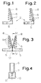
- Each electrode 2 has a connecting leg 5 and a spark horn running at an acute angle to the connecting leg 5 6 on. 1 to 3 and 6 show, the acute angle relates between the connecting leg 5 and the spark horn 6 on the functional surface of the Spark horns 6.
- the spark horns 6 of the two - spaced apart Electrodes 2 together form the air breakdown spark gap 3. that the spark horns 6 of the electrodes 2 in the manner explained above the air breakdown spark gap is at an acute angle to the connecting legs 5 3 executed at an acute angle; the angle between each other facing spark horns 6 of the electrodes 2 is preferably about 30 °.
- the spark horns 6 are the electrodes 2 in their areas adjacent to the connecting leg 5 with a parallel to the connecting legs 5 extending holes 7 provided in the embodiment are realized in the center of the spark horns 6 of the electrodes 2 (cf. in particular 4 and 5).
- FIG. 2 shows an electrode 2 in which the spark horn 6 has two bores 7 provided one above the other; compared to the electrode 2 according to FIG. list for the electrode 2 according to FIG. 2 below the bore 7 with which the 1, a further bore 7 is realized.
- holes 7 ensure that at the moment the response of the overvoltage protection element 1, ie the ignition, the resultant Arc next to the holes 7 by a thermal and / or electrical and / or magnetic pressure and / or force effect is "set in motion", thus migrates away from its point of origin.
- the figures show that in the illustrated embodiment the spark horns 6 of the electrodes 2 on both sides with a chamfer 8 are provided, are convex on their mutually facing sides and on their sides facing away from one another with the spark horns transverse to the longitudinal extent 6 extending slots 9 are provided; instead of the shown transverse Slots 9 are also possible.
- the chamfering of the spark horns 6 of the electrodes 2 prevents material abrasion on the edges of the Spark horns 6 is coming.
- arcing arises preferably in the center of the spark horns 6 arises and in the middle of the ends or tips of the spark horns 6 running.
- an inventive Surge protection element 1 is between the opposite ends the connecting leg 5 of the two electrodes 2 a - triggering a sliding discharge - Ignition aid 10 is provided, which preferably consists of an insulating material in the event of a change in state, for example heating, no carbon in emits functional impairment, and slightly, preferably 0.1 mm or more, in the air breakdown spark gap formed by the spark horns 6 of the electrodes 2 3 protrudes; the ignition aid 10 actually extends to the middle of the holes 7 into the air breakdown spark gap 3. Otherwise, the Ignition aid 10, as shown in FIGS. 4 and 5, on their air breakdown spark gap 3 facing side V-shaped and with one into the air breakdown spark gap 3 reaching narrow slot 11 provided. The slot 11 in the ignition aid 10 has a positive influence on the response voltage.
- an overvoltage protection element according to the invention 1 is, as it were, in the measures described above the narrowest part of the air breakdown spark gap 3, i.e. where there is a response or ignition takes place, an auxiliary air flashover spark gap is integrated.
- This integrated auxiliary air rollover spark gap has a relatively constant and above all, lower response voltage than that of the actual surge protection serving air breakdown spark gap 3. Once addressed, at one relatively constant low response voltage, leads the ignited auxiliary air arcing spark gap to a "sudden" ignition of the air breakdown spark gap 3 with a relatively high current carrying capacity.
- FIG. 5 and 6 and 7 to 10 show that in the illustrated embodiment of an overvoltage protection element 1 according to the invention also with respect to the Housing 4 special measures are realized. Because what is not shown applies is that the housing 4 is partially made of a plastic, which when heated or does not emit carbon or partially with a combustion such plastic is lined. The problems described earlier, the then occur when the housing is made of plastic, which when heated or emits carbon from a combustion are therefore eliminated.
- an inventive Surge protection element 1 also applies that the spark horns 6th the housing cover 13 adjacent to the electrodes 2 and made of electrically conductive material, preferably consists of erosion-resistant material, in particular of copper tungsten. Then there is the distance between the ends adjacent to the housing cover 13 the spark horns 6 of the electrodes 2 and the housing cover 13 are selected that between the ends of the spark horns 6 adjacent to the housing cover 13 and the housing cover 13 arcs can arise.
- an inventive Surge protection element 1 to which an electrode according to FIG. 2 belongs, thus one in which each spark horn 6 has two bores provided one above the other 7, the second, lower bore 7 is effective when the Ignition aid 10 burned down between the connecting legs 5 of the electrodes 2 is.
- the second bore 7 thus serves as a kind of security that the invention Surge protection element 1 also works in such a case.
- FIG. 7 to 10 in constructive detail such a preferred embodiment of an inventive Overvoltage protection element 1.
- the electrodes 2 are shown in such a way that the air breakdown spark gap 3 opens from the bottom up.
- the electrodes 2 are arranged so that the air breakdown spark gap 3 opens from top to bottom.
- the constructive Detail shown in FIGS. 7 to 10 embodiment of an inventive Surge protection element 1 the functionally essential elements, that is, the electrodes 2 with the spark horns 6 and the ignition aid 10 essentially carried out as described above in connection with FIGS. 1 to 6 in detail has been so that relevant statements in connection with FIG. 7th to 10 spare. 7 to 10 show above all structural details in relation on the housing 4.
- the housing 4 is a specially designed housing cover 13 assigned.
- This housing cover 13 has a dome-like shape 14 into which a holder 15 receiving the electrodes 2 is inserted.
- the housing cover 13 is connected to the actual housing 2 by internal screws 16.
- the housing 4 at least partially consists of a Plastic consists of no carbon when heated or burned emits or is at least partially lined with such a plastic.
- the housing 4 thus has a lining 17 made of a plastic which does not give off carbon when heated or burned.
- the spark horns 6 of the electrodes 2 adjacent housing cover 13 made of electrical consists of conductive material
- the distance between the housing cover 13th adjacent ends of the spark horns 6 of the electrodes 2 and the housing cover 13 is chosen so that between the housing cover 13 adjacent ends of the Spark horns 6 and the housing cover 13 arcs can occur.
- FIGS. 7 to 10 Embodiment achieved in that in the housing 4, the ends of the spark horns 6 opposite the electrodes 2, an insert 19 made of electrically conductive material, again preferably made of erosion-resistant material.
- FIGS. 7 to 9 show that the housing 4- and, accordingly, the housing cover 13 - is designed asymmetrically.
- the screws 16 with which the Housing cover 13 is connected to the housing 4 on the other hand connector body 20th for connecting electrical lines, not shown.
- Below the screws 16, with which the housing cover 13 is connected to the housing 14 Blow-out openings 21 realized.
- FIGS. 7 to 10 The constructional design shown in FIGS. 7 to 10 is also essential to the invention of the housing 4 and the arrangement of the electrodes 2 in the housing 4 and in Housing cover 13, also to the extent that this is only shown in detail in FIGS. 7 to 10 is, also insofar as this is not described before, especially insofar as as claims are not directed to these structural details.
Landscapes
- Emergency Protection Circuit Devices (AREA)
- Thermistors And Varistors (AREA)
Description
- Fig. 1
- eine Seitenansicht einer bevorzugten ersten Ausführungsform einer Elektrode eines erfindungsgemäßen Überspannungsschutzelements,
- Fig. 2
- eine Seitenansicht einer bevorzugten zweiten Ausführungsform einer Elektrode eines erfindungsgemäßen Überspannungsschutzelements,
- Fig. 3
- eine Seitenansicht von zwei zusammenwirkenden Elektroden nach Fig. 1,
- Fig. 4
- einen Schnitt durch die Elektroden nach Fig. 3 längs der Linie IV - IV,
- Fig. 5
- einen Querschnitt durch eine nur schematisch dargestellte bevorzugte Ausführungsform eines erfindungsgemäßen Überspannungsschutzelements,
- Fig. 6
- einen Längsschnitt durch das Überspannungsschutzelement nach Fig. 5,
- Fig. 7
- einen Längsschnitt durch eine detailliert dargestellte bevorzugte Ausführungsform eines erfindungsgemäßen Überspannungsschutzelements,
- Fig. 8
- eine Draufsicht auf das Überspannungsschutzelement nach Fig. 7, teilweise geschnitten,
- Fig. 9
- einen Schnitt durch das Überspannungsschutzelement nach Fig. 7 (längs der Linie IX - IX in Fig. 8) und
- Fig. 10
- einen Schnitt durch das Überspannungsschutzelement nach Fig. 7 (längs der Linie X - X in Fig. 8).
Claims (15)
- Überspannungsschutzelement zur Ableitung von transienten Überspannungen, mit zwei Elektroden (2), einer zwischen den Elektroden (2) wirksamen Luft-Durchschlag-Funkenstrecke (3) und einem die Elektroden (2) aufnehmenden Gehäuse (4), wobei jede Elektrode (2) einen Anschlußschenkel (5) und ein unter einem spitzen Winkel zu dem Anschlußschenkel (5) verlaufendes Funkenhorn (6) aufweist und die Funkenhörner (6) der beiden - mit Abstand zueinander angeordneten - Elektroden (2) zusammen die Luft-Durchschlag-Funkenstrecke (3) bilden, wobei zwischen den sich gegenüberstehenden Enden der Anschlußschenkel (5) der beiden Elektroden (2) eine - eine Gleitentladung auslösende - Zündhilfe (10) vorgesehen ist, dadurch gekennzeichnet, daß die Zündhilfe (10) an ihrer der Luft-Durchschlag-Funkenstrecke (3) zugewandten Seite V-förmig oder konkav ausgebildet ist und daß die Zündhilfe (10) mit einem schmalen Schlitz (11) versehen ist, der in die V-förmig oder konkav ausgebildete Seite der Zündhilfe (10) mündet und bis in die Luft-Durchschlag-Funkenstrecke (3) reicht.
- Überspannungsschutzelement nach Anspruch 1, dadurch gekennzeichnet, daß die Funkenhörner (6) der Elektroden (2) in ihren an die Anschlußschenkel (5) angrenzenden Bereichen mit einer parallel zu den Anschlußschenkeln (5) verlaufenden Bohrung (7) - vorzugsweise mit einem Durchmesser von weniger als 2 mm, insbesondere von ca. 1,5 mm - versehen sind.
- Überspannungsschutzelement nach Anspruch 1 oder 2, dadurch gekennzeichnet, daß die Zündhilfe (10) aus einem Isolierstoff besteht, der bei einer Zustandsänderung, beispielsweise einer Erhitzung, keinen Kohlenstoff in funktionsbeeinträchtigendem Maße abgibt.
- Überspannungsschutzelement nach Anspruch 2 oder 3, dadurch gekennzeichnet. daß die Zündhilfe (10) geringfügig, vorzugsweise 0,1 mm oder mehr, in die von den Funkenhörnern (6) der Elektroden (2) gebildete Luft-Durchschlag-Funkenstrecke (3) hineinragt, vorzugsweise bis in die Mitte der Bohrungen (7) oder geringfügig mehr in die Luft-Durchschlag-Funkenstrecke (3) hineinragt.
- Überspannungsschutzelement nach einem der Ansprüche 2 bis 4, dadurch gekennzeichnet, daß der Winkel zwischen den einander zugewandten Funkenhörnern (6) etwa 30° beträgt.
- Überspannungsschutzelement nach einem der Ansprüche 2 oder 5, dadurch gekennzeichnet, daß die Funkenhörner (6) eine Breite von weniger als 15 mm, insbesondere von ca. 8 mm aufweisen.
- Überspannungsschutzelement nach einem der Ansprüche 2 bis 6, dadurch gekennzeichnet, daß die Bohrungen (7) mittig in den Funkenhörnern (6) verwirklicht sind.
- Überspannungsschutzelement nach einem der Ansprüche 2 bis 7, dadurch gekennzeichnet, daß jedes Funkenhorn (6) jeder Elektrode (2) mit zwei übereinander vorgesehenen Bohrungen (7) versehen ist.
- Überspannungsschutzelement nach einem der Ansprüche 2 bis 8, dadurch gekennzeichnet, daß die Funkenhörner (6) der Elektroden (2) an beiden Seiten jeweils mit einer Fase (8) oder einer Rundung versehen sind.
- Überspannungsschutzelement nach einem der Ansprüche 2 bis 9, dadurch gekennzeichnet, daß die Funkenhörner (6) der Elektroden (2) an ihren einander zugewandten Seiten konvex ausgebildet sind.
- Überspannungsschutzelement nach einem der Ansprüche 2 bis 10, dadurch gekennzeichnet, daß die Funkenhörner (6) der Elektroden (2) an ihren voneinander abgewandten Seiten mit - vorzugsweise quer zur Längserstreckung der Funkenhörner (6) verlaufenden - Schlitzen (9) versehen sind.
- Überspannungsschutzelement nach einem der Ansprüche 1 bis 11, dadurch gekennzeichnet, daß das Gehäuse (4) zumindest teilweise aus einem Kunststoff besteht, der bei einer Erhitzung bzw. einer Verbrennung keinen Kohlenstoff abgibt oder zumindest teilweise mit einem solchen Kunststoff ausgekleidet ist.
- Überspannungsschutzelement nach einem der Ansprüche 1 bis 12, dadurch gekennzeichnet, daß die Seitenwandungen (12) des Gehäuses (4) relativ nahe an die Funkenhörner (6) der Elektroden (2) herangezogen sind, vorzugsweise bis an die Funkenhörner (6) der Elektroden (2) herangezogen sind.
- Überspannungsschutzelement nach einem der Ansprüche 1 bis 13, dadurch gekennzeichnet, daß der den Funkenhörnern (6) der Elektrode (2) benachbarte Gehäusedeckel (13) aus elektrisch leitendem Material, vorzugsweise aus abbrandfestem Material, insbesondere aus Kupferwolfram besteht.
- Überspannungsschutzelement nach Anspruch 14, dadurch gekennzeichnet, daß der Abstand zwischen den dem Gehäusedeckel (13) benachbarten Enden der Funkenhörner (6) der Elektroden (2) und dem Gehäusedeckel (13) so gewählt ist, daß zwischen den dem Gehäusedeckel (13) benachbarten Enden der Funkenhörner (6) und dem Gehäusedeckel (13) Lichtbögen entstehen können.
Applications Claiming Priority (5)
| Application Number | Priority Date | Filing Date | Title |
|---|---|---|---|
| DE4317933 | 1993-05-31 | ||
| DE4317933 | 1993-05-31 | ||
| DE4402615A DE4402615C3 (de) | 1993-05-31 | 1994-01-28 | Überspannungsschutzelement |
| DE4402615 | 1994-01-28 | ||
| EP94108276A EP0635919B1 (de) | 1993-05-31 | 1994-05-30 | Überspannungsschutzelement |
Related Parent Applications (2)
| Application Number | Title | Priority Date | Filing Date |
|---|---|---|---|
| EP94108276A Division EP0635919B1 (de) | 1993-05-31 | 1994-05-30 | Überspannungsschutzelement |
| EP94108276.0 Division | 1994-05-30 |
Publications (3)
| Publication Number | Publication Date |
|---|---|
| EP0786844A2 EP0786844A2 (de) | 1997-07-30 |
| EP0786844A3 EP0786844A3 (de) | 1997-10-22 |
| EP0786844B1 true EP0786844B1 (de) | 2001-01-17 |
Family
ID=27205139
Family Applications (1)
| Application Number | Title | Priority Date | Filing Date |
|---|---|---|---|
| EP97105664A Expired - Lifetime EP0786844B1 (de) | 1993-05-31 | 1994-05-30 | Überspannungsschutzelement |
Country Status (3)
| Country | Link |
|---|---|
| US (1) | US5604400A (de) |
| EP (1) | EP0786844B1 (de) |
| DE (3) | DE4447567B4 (de) |
Families Citing this family (5)
| Publication number | Priority date | Publication date | Assignee | Title |
|---|---|---|---|---|
| DE19818674B4 (de) * | 1998-04-27 | 2004-04-29 | Phoenix Contact Gmbh & Co. Kg | Überspannungsschutzelement |
| DE10008764A1 (de) | 1999-03-04 | 2000-09-28 | Phoenix Contact Gmbh & Co | Überspannungsschutzeinrichtung |
| US7023307B2 (en) * | 2003-11-06 | 2006-04-04 | Pratt & Whitney Canada Corp. | Electro-magnetically enhanced current interrupter |
| DE10357945A1 (de) * | 2003-12-09 | 2005-07-14 | Phoenix Contact Gmbh & Co. Kg | Überspannungsschutzeinrichtung |
| DE202004020260U1 (de) * | 2004-12-28 | 2005-02-24 | Phoenix Contact Gmbh & Co. Kg | Überspannungsschutzeinrichtung |
Family Cites Families (20)
| Publication number | Priority date | Publication date | Assignee | Title |
|---|---|---|---|---|
| US1144029A (en) * | 1913-03-19 | 1915-06-22 | Gen Electric | Protective device. |
| CH391069A (de) * | 1961-03-23 | 1965-04-30 | Licentia Gmbh | Magnetisch beblasene Löschfunkenstrecke für Überspannungsableiter |
| GB939459A (en) * | 1962-08-14 | 1963-10-16 | Licentia Gmbh | Improvements in and relating to arc gap devices |
| CH465046A (de) * | 1968-01-11 | 1968-11-15 | Sprecher & Schuh Ag | Löschfunkenstreckenanordnung, insbesondere für Überspannungsableiter |
| US3780350A (en) * | 1971-12-16 | 1973-12-18 | Gen Signal Corp | Surge arrester |
| US3795840A (en) * | 1972-11-29 | 1974-03-05 | Nasa | Overvoltage protection network |
| US3968393A (en) * | 1975-03-27 | 1976-07-06 | Tokyo Shibaura Electric Co., Ltd. | Spark gap device for a lightning arrestor |
| FR2337417A1 (fr) * | 1975-12-30 | 1977-07-29 | Comp Generale Electricite | Eclateur declenche dans un gaz |
| US4100588A (en) * | 1977-03-16 | 1978-07-11 | General Electric Company | Electrical overvoltage surge arrester with varistor heat transfer and sinking means |
| DE2718188C3 (de) * | 1977-04-23 | 1984-07-05 | Dehn + Söhne GmbH + Co KG, 8500 Nürnberg | Überspannungsschutzgerät |
| US4249224A (en) * | 1979-03-07 | 1981-02-03 | Reliable Electric Company | Surge voltage arrester with fail-safe feature |
| DE2934236C2 (de) * | 1979-08-24 | 1983-02-24 | Aeg-Telefunken Ag, 1000 Berlin Und 6000 Frankfurt | Überspannungsableiter mit Funkenstrecke |
| DE2934235A1 (de) * | 1979-08-24 | 1981-03-26 | Ant Nachrichtentechnik Gmbh, 71522 Backnang | Netzanschluss mit ueberspannungsableitern |
| DE3016265C2 (de) * | 1980-04-26 | 1984-05-17 | ANT Nachrichtentechnik GmbH, 7150 Backnang | Überspannungsableiter mit Funkenstrecke |
| DE3100924A1 (de) * | 1981-01-14 | 1982-08-05 | Siemens AG, 1000 Berlin und 8000 München | "gasentladungs-ueberspannungsableiter" |
| DE3101354C2 (de) * | 1981-01-17 | 1984-11-29 | Dehn + Söhne GmbH + Co KG, 8500 Nürnberg | Funkenstrecke für die Begrenzung von Überspannungen |
| DE3716997A1 (de) * | 1987-05-21 | 1988-12-08 | Phoenix Elekt | Ueberspannungsschutzgeraet |
| DE4141681C2 (de) * | 1991-12-17 | 1996-11-14 | Phoenix Contact Gmbh & Co | Überspannungsschutzelement |
| DE4141682C2 (de) * | 1991-12-17 | 1996-09-26 | Phoenix Contact Gmbh & Co | Überspannungsschutzelement |
| DE4244051C2 (de) * | 1992-12-28 | 1996-03-14 | Phoenix Contact Gmbh & Co | Überspannungsschutzelement |
-
1994
- 1994-01-28 DE DE4447567.5T patent/DE4447567B4/de not_active Expired - Lifetime
- 1994-05-30 EP EP97105664A patent/EP0786844B1/de not_active Expired - Lifetime
- 1994-05-30 DE DE59409641T patent/DE59409641D1/de not_active Expired - Lifetime
- 1994-05-30 DE DE59406601T patent/DE59406601D1/de not_active Expired - Lifetime
-
1996
- 1996-04-10 US US08/631,825 patent/US5604400A/en not_active Expired - Lifetime
Also Published As
| Publication number | Publication date |
|---|---|
| US5604400A (en) | 1997-02-18 |
| DE59409641D1 (de) | 2001-02-22 |
| DE4447567B4 (de) | 2019-01-03 |
| EP0786844A3 (de) | 1997-10-22 |
| DE59406601D1 (de) | 1998-09-10 |
| EP0786844A2 (de) | 1997-07-30 |
Similar Documents
| Publication | Publication Date | Title |
|---|---|---|
| DE4402615C2 (de) | Überspannungsschutzelement | |
| EP0706245B1 (de) | Überspannungsschutzelement | |
| EP1033798B1 (de) | Überspannungsschutzeinrichtung | |
| DE102011102937B4 (de) | Anordnung zur Zündung von Funkenstrecken | |
| DE4141681C2 (de) | Überspannungsschutzelement | |
| EP0635919B1 (de) | Überspannungsschutzelement | |
| EP1423894A1 (de) | Überspannungsschutzeinrichtung | |
| DE4439730C2 (de) | Überspannungsschutzelement | |
| EP1461852B1 (de) | Mehrpoliges überspannungsschutzsystem und verfahren zum sicheren betrieb eines mehrpoligen überspannungsschutzsystems | |
| EP1692751B1 (de) | Überspannungsschutzeinrichtung | |
| DE4244051C2 (de) | Überspannungsschutzelement | |
| DE4435968C2 (de) | Überspannungsschutzelement | |
| DE10312820B4 (de) | Lichtbogenlöschblechanordnung für einen elektrischen Schalter, insbesondere einen elektrischen Leitungsschutzschalter | |
| DE4447567B4 (de) | Überspannungsschutzelement | |
| DE3910435C2 (de) | ||
| DE69828861T2 (de) | Funkenstreckenvorrichtung zum Schutz von elektrischen Leitungen und/oder elektrischen Apparaten gegen zeitlichen Überspannungen | |
| EP3931921B1 (de) | Blitzschutz-funkenstrecke | |
| DE4141682A1 (de) | Ueberspannungsschutzelement | |
| EP3834260B1 (de) | Anordnung zur zündung von funkenstrecken | |
| DE10146728A1 (de) | Überspannungsschutzeinrichtung | |
| DE1908152A1 (de) | Funkenstreckenanordnung fuer UEberschlagssicherung | |
| EP0920098B1 (de) | Überspannungsschutzelement | |
| DE2140876A1 (de) | Funkenstreckenanordnung | |
| DE10120563A1 (de) | Überspannungsschutzelement und Überspannungsschutzeinrichtung | |
| DE854821C (de) | Funkenstreckenanordnung fuer einen Blitzableiter |
Legal Events
| Date | Code | Title | Description |
|---|---|---|---|
| PUAI | Public reference made under article 153(3) epc to a published international application that has entered the european phase |
Free format text: ORIGINAL CODE: 0009012 |
|
| AC | Divisional application: reference to earlier application |
Ref document number: 635919 Country of ref document: EP |
|
| AK | Designated contracting states |
Kind code of ref document: A2 Designated state(s): AT CH DE ES FR GB IT LI NL |
|
| PUAL | Search report despatched |
Free format text: ORIGINAL CODE: 0009013 |
|
| AK | Designated contracting states |
Kind code of ref document: A3 Designated state(s): AT CH DE ES FR GB IT LI NL |
|
| 17P | Request for examination filed |
Effective date: 19971229 |
|
| 17Q | First examination report despatched |
Effective date: 19980303 |
|
| GRAG | Despatch of communication of intention to grant |
Free format text: ORIGINAL CODE: EPIDOS AGRA |
|
| 17Q | First examination report despatched |
Effective date: 19980303 |
|
| GRAG | Despatch of communication of intention to grant |
Free format text: ORIGINAL CODE: EPIDOS AGRA |
|
| GRAH | Despatch of communication of intention to grant a patent |
Free format text: ORIGINAL CODE: EPIDOS IGRA |
|
| GRAH | Despatch of communication of intention to grant a patent |
Free format text: ORIGINAL CODE: EPIDOS IGRA |
|
| GRAA | (expected) grant |
Free format text: ORIGINAL CODE: 0009210 |
|
| AC | Divisional application: reference to earlier application |
Ref document number: 635919 Country of ref document: EP |
|
| AK | Designated contracting states |
Kind code of ref document: B1 Designated state(s): AT CH DE ES FR GB IT LI NL |
|
| REF | Corresponds to: |
Ref document number: 198813 Country of ref document: AT Date of ref document: 20010215 Kind code of ref document: T |
|
| REG | Reference to a national code |
Ref country code: CH Ref legal event code: EP |
|
| GBT | Gb: translation of ep patent filed (gb section 77(6)(a)/1977) |
Effective date: 20010117 |
|
| REF | Corresponds to: |
Ref document number: 59409641 Country of ref document: DE Date of ref document: 20010222 |
|
| REG | Reference to a national code |
Ref country code: CH Ref legal event code: NV Representative=s name: KELLER & PARTNER PATENTANWAELTE AG |
|
| ET | Fr: translation filed | ||
| ITF | It: translation for a ep patent filed | ||
| REG | Reference to a national code |
Ref country code: ES Ref legal event code: FG2A Ref document number: 2154431 Country of ref document: ES Kind code of ref document: T3 |
|
| PLBE | No opposition filed within time limit |
Free format text: ORIGINAL CODE: 0009261 |
|
| STAA | Information on the status of an ep patent application or granted ep patent |
Free format text: STATUS: NO OPPOSITION FILED WITHIN TIME LIMIT |
|
| REG | Reference to a national code |
Ref country code: GB Ref legal event code: IF02 |
|
| 26N | No opposition filed | ||
| PGFP | Annual fee paid to national office [announced via postgrant information from national office to epo] |
Ref country code: ES Payment date: 20120523 Year of fee payment: 19 |
|
| PGFP | Annual fee paid to national office [announced via postgrant information from national office to epo] |
Ref country code: AT Payment date: 20120523 Year of fee payment: 19 |
|
| PGFP | Annual fee paid to national office [announced via postgrant information from national office to epo] |
Ref country code: GB Payment date: 20130521 Year of fee payment: 20 Ref country code: CH Payment date: 20130522 Year of fee payment: 20 Ref country code: DE Payment date: 20130503 Year of fee payment: 20 |
|
| PGFP | Annual fee paid to national office [announced via postgrant information from national office to epo] |
Ref country code: NL Payment date: 20130516 Year of fee payment: 20 Ref country code: FR Payment date: 20130605 Year of fee payment: 20 Ref country code: IT Payment date: 20130525 Year of fee payment: 20 |
|
| REG | Reference to a national code |
Ref country code: DE Ref legal event code: R071 Ref document number: 59409641 Country of ref document: DE |
|
| REG | Reference to a national code |
Ref country code: NL Ref legal event code: V4 Effective date: 20140530 |
|
| REG | Reference to a national code |
Ref country code: CH Ref legal event code: PL |
|
| REG | Reference to a national code |
Ref country code: GB Ref legal event code: PE20 Expiry date: 20140529 |
|
| REG | Reference to a national code |
Ref country code: AT Ref legal event code: MK07 Ref document number: 198813 Country of ref document: AT Kind code of ref document: T Effective date: 20140530 |
|
| PG25 | Lapsed in a contracting state [announced via postgrant information from national office to epo] |
Ref country code: GB Free format text: LAPSE BECAUSE OF EXPIRATION OF PROTECTION Effective date: 20140529 |
|
| PG25 | Lapsed in a contracting state [announced via postgrant information from national office to epo] |
Ref country code: DE Free format text: LAPSE BECAUSE OF EXPIRATION OF PROTECTION Effective date: 20140531 |
|
| REG | Reference to a national code |
Ref country code: ES Ref legal event code: FD2A Effective date: 20140926 |
|
| PG25 | Lapsed in a contracting state [announced via postgrant information from national office to epo] |
Ref country code: ES Free format text: LAPSE BECAUSE OF EXPIRATION OF PROTECTION Effective date: 20140531 |