EP0786833B1 - Socket with an additionally function modul - Google Patents
Socket with an additionally function modul Download PDFInfo
- Publication number
- EP0786833B1 EP0786833B1 EP97100696A EP97100696A EP0786833B1 EP 0786833 B1 EP0786833 B1 EP 0786833B1 EP 97100696 A EP97100696 A EP 97100696A EP 97100696 A EP97100696 A EP 97100696A EP 0786833 B1 EP0786833 B1 EP 0786833B1
- Authority
- EP
- European Patent Office
- Prior art keywords
- plug connector
- circuit board
- module
- connector according
- socket
- Prior art date
- Legal status (The legal status is an assumption and is not a legal conclusion. Google has not performed a legal analysis and makes no representation as to the accuracy of the status listed.)
- Expired - Lifetime
Links
Images


Classifications
-
- H—ELECTRICITY
- H01—ELECTRIC ELEMENTS
- H01R—ELECTRICALLY-CONDUCTIVE CONNECTIONS; STRUCTURAL ASSOCIATIONS OF A PLURALITY OF MUTUALLY-INSULATED ELECTRICAL CONNECTING ELEMENTS; COUPLING DEVICES; CURRENT COLLECTORS
- H01R13/00—Details of coupling devices of the kinds covered by groups H01R12/70 or H01R24/00 - H01R33/00
- H01R13/66—Structural association with built-in electrical component
- H01R13/665—Structural association with built-in electrical component with built-in electronic circuit
-
- H—ELECTRICITY
- H01—ELECTRIC ELEMENTS
- H01R—ELECTRICALLY-CONDUCTIVE CONNECTIONS; STRUCTURAL ASSOCIATIONS OF A PLURALITY OF MUTUALLY-INSULATED ELECTRICAL CONNECTING ELEMENTS; COUPLING DEVICES; CURRENT COLLECTORS
- H01R13/00—Details of coupling devices of the kinds covered by groups H01R12/70 or H01R24/00 - H01R33/00
- H01R13/648—Protective earth or shield arrangements on coupling devices, e.g. anti-static shielding
- H01R13/655—Protective earth or shield arrangements on coupling devices, e.g. anti-static shielding with earth brace
-
- H—ELECTRICITY
- H01—ELECTRIC ELEMENTS
- H01R—ELECTRICALLY-CONDUCTIVE CONNECTIONS; STRUCTURAL ASSOCIATIONS OF A PLURALITY OF MUTUALLY-INSULATED ELECTRICAL CONNECTING ELEMENTS; COUPLING DEVICES; CURRENT COLLECTORS
- H01R24/00—Two-part coupling devices, or either of their cooperating parts, characterised by their overall structure
- H01R24/76—Two-part coupling devices, or either of their cooperating parts, characterised by their overall structure with sockets, clips or analogous contacts and secured to apparatus or structure, e.g. to a wall
- H01R24/78—Two-part coupling devices, or either of their cooperating parts, characterised by their overall structure with sockets, clips or analogous contacts and secured to apparatus or structure, e.g. to a wall with additional earth or shield contacts
Definitions
- the invention relates to a socket consisting of a Insulating base with a pair of sockets in the middle, which engages with connector pins of a connector forms a switch contact, a cover plate made of insulating material for the socket and one with the insulating base electrically and mechanically connectable module for Additional functions according to the preamble of claim 1.
- an electrotechnical installation device for example in the form of a socket and thus according to The preamble of claim 1 is known in modular design, at by the from the building side of the socket whose insulating base is pluggable module of the socket Additional functions are given.
- the electrical contact spring-loaded contacts are used for the pluggable module achieved when a connector pin of a connector in the Socket pair of the socket is inserted.
- DE-U-295 07 448 shows a socket consisting of an insulating base with a central one Pair of sockets, which in engagement with connector pins Plug forms a switching contact. There is provided to leave a space next to the insulating base or to use this free space so that arranged on a plate can protrude electronic components.
- those for the connection between are problematic the actual surge protection components and the electrical connections of the protective contact socket necessary flexible lines. This leads to essentials Disadvantages in terms of assembly effort and risk of reverse polarity.
- the components of a Surge protection device positioned so that it in Free space that can be found just like the - Subject of EP-0 654 864 between the bottom of the flush-mounted box and the lower surface opposite this floor of the insulating base. It should be noted that the space between the bottom of the flush-mounted box and the this floor facing surface of the insulating base in its height due to the prescribed dimensions of the Flush-mounted box and the required dimension of the insulating base limited and therefore not expandable is.
- the invention is therefore initially based on the problem that To design the socket known from EP A1 0 654 864 in such a way that even voluminous modules are available standing space while observing the required internal dimensions a socket with an insulating base can be.
- the module contains an overvoltage protection device, which is parallel to the bottom of the PCB with a minimum of has two corners, including the one in detail their arrangement explained varistors.
- the circuit board can only on one side, namely the side facing the insulating base, be equipped. A PCB assembly on both Pages are not required. Because it is not necessary is on the underside facing away from the insulating base the circuit board components of surge protection, in particular applied varistors or gas discharge tubes to accommodate, the task-related advantage of Space saving. You can also see the bottom of the Electrical elements of the insulating base Keep the top of the PCB small.
- This overvoltage protection namely the varistors on the other hand, arranged and protruding in the corners of the circuit board in the created space next to the insulating base into it.
- the formation of the socket base also contribute Creation of free space on the one hand and the associated Design of the module, in particular in the form of an overvoltage protection device with two relatively large varistors, to achieve the object of the invention in a Surge protection module together.
- the embodiment according to claim 4 gives the advantage that both the insulating base and the overvoltage protection device against damage during storage and is protected during transport, moreover it can be easily used Protection against accidental contact.
- the configurations of the socket according to claims 5, 6 and 7 have the advantage that the assembly of surge protective device and insulating base with the help the cap quickly and easily done can be.
- an optical display is provided as to whether the surge protection elements such a surge protection device are still fine.
- Corresponding display means are usually arranged in a corner of the circuit board.
- a corresponding optical signaling through the socket to allow outside including a clear one Distinguishing different signals are the characteristics of claim 9 provided.
- the signal lamps are located on two in the Distance from the corners of the socket. she are both clearly visible from the room side as well as differentiating from each other. Even in bright light, the user is able to use the spatial separation, for example a red from a green display, recognizability given at all times.
- An arrangement of the fuses is advantageous a compact, spatially adjacent to the varistors space-saving design of the socket and optimal heat transfer from the varistor to this thermal fuses reached.
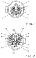
- the socket according to the invention consists of an insulating base 1 with one in the middle of the socket Pair of sockets 2, which in engagement with connector pins Plug forms a switching contact. Furthermore, the Socket on a cover plate made of insulating material, which in the drawing is not shown, and a protective contact 3. With the insulating base 1 is a module 4 for Additional functions, in particular also one below with 4 numbered surge protection device, electrical and mechanically connectable. According to the invention, the insulating base 1 asymmetrical to socket pair 2 and thus Or type asymmetrical to the side wall 12 'of the flush-mounted box 12 arranged that the resulting space 5 for the accommodation of parts of the surge protection device 4 can be used.
- the free space 5 extends at least over the entire height H of the insulating base (see also Fig. 3). However, if spatially possible, also in the space 5 'below in FIG. 3 and / or - as also shown in Fig. 3 - in the extend through a bracket indicated upper space 5 ".
- Fig. 1 shows the asymmetrical configuration already explained device and arrangement of the insulating base 1 to the sockets 2. Furthermore, Fig. 1 shows that the dashed there Lines indicated free space 5 about 1/3 to 1/2 of that of the Flush box 12 surrounding space.
- the overvoltage protection device 4 has a parallel to the bottom 6 of the insulating base 1 PCB 7 on.
- the in the known prior art essential square circuit board is in the invention Socket designed such that the circuit board 7th corresponding bulges 14 in at least two corners 7 ′ having. At these bulges 14 of the circuit board 7 are Varistors 8 arranged opposite to the circuit board 7 raise vertically and into the space 5 between the insulating base 1 and surrounding junction box 12 protrude.
- the insulating base 1 and the overvoltage protection device 4 from a cap 13 open towards these parts 1, 4 surrounded by insulating material.
- the cap 13 In order to install the surge protection device 4 or their replacement in the event of service quickly and easily To carry out handles, the cap 13 has both locking means 15 for attachment to the surge protection device 4, as well as locking means 16 for attachment to the insulating base 1 on.
- the cap 13 is by means of locking hooks 15 attached to the printed circuit board 7, the printed circuit board 7 even serves as a locking edge. To unlatch only the plastic snap hooks 15 pushed to the side become.
- the recesses are just as easy to operate 16 in the cap 13 and protrusions 17 of the insulating base 1 existing locking device.
- socket according to the invention are spatially adjacent to the varistors 8 display means 9 arranged, which through the cover plate of the socket go.
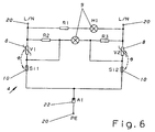
- FIG. 6 is the circuit diagram of such an overvoltage protection device 4 shown.
- the Phase conductor L or neutral conductor N via the knife contacts 20 of the circuit board 7 connected.
- the parallel connection off Resistor R1 and the one display means 9 and resistor R2, R3 and the other display means 9 shows the operating state the overvoltage protection device 4. It serves the display 9 in the parallel branch with resistance R1 of the display, that the surge protection device is intact. As soon as the surge protection element or elements are destroyed 8 has taken place, this is done via the parallel branch with that arranged in series with resistors R2 and R3 Display means 9 signals.
- the circuit consisting of the overvoltage protection elements, e.g. Varistors 8 and thermal monitoring fuses 10 is matched so that these fuses the overloaded varistor split off.
- the main advantages of the invention are that one despite the here due to the internal dimensions of the flush-mounted box given a relatively large surge protection device,
- the varistors explained are intended can accommodate in the manner explained. It is without the need for additional space Housing of thermal fuses given.
- the electrical Plug contacts can be stable and largely capable of withstanding surge currents his. It is an easy assembly and disassembly both in mechanical and electrical terms of the Module on the insulating base possible. This easy interchangeability is for practical operation, especially the quick retrofitting without considering the installation L / N an advantage.
Abstract
Description
Die Erfindung betrifft eine Steckdose bestehend aus einem
Isolierstoffsockel mit einem mittig angeordneten Buchsenpaar,
welches im Eingriff mit Steckerstiften eines Steckers
einen Schaltkontakt bildet, einer Abdeckplatte aus Isolierstoff
für die Steckdose und einem mit dem Isolierstoffsockel
elektrisch und mechanisch verbindbaren Modul für
Zusatzfunktionen gemäß Oberbegriff des Patentanspruchs 1.The invention relates to a socket consisting of a
Insulating base with a pair of sockets in the middle,
which engages with connector pins of a connector
forms a switch contact, a cover plate made of insulating material
for the socket and one with the insulating base
electrically and mechanically connectable module for
Additional functions according to the preamble of
Um einen Isolierstoffsockel von Steckdosen für Zusatzfunktionen
in seiner Höhe unverändert zu belassen, ist aus der
EP-A-0 654 864 ein elektrotechnisches Installationsgerät,
beispielsweise in Form einer Steckdose und damit gemäß dem
Oberbegriff des Anspruches 1 in Modulbauweise bekannt, bei
der durch das von der Bauwerksseite der Steckdose her an
deren Isolierstoffsockel ansteckbare Modul der Steckdose
Zusatzfunktionen gegeben werden. Die elektrische Kontaktgabe
für das steckbare Modul wird jeweils durch gefederte Kontakte
erzielt, wenn ein Steckerstift eines Steckers in das
Buchsenpaar der Steckdose eingeführt wird.To an insulating base of sockets for additional functions
to remain unchanged in height is from the
EP-A-0 654 864 an electrotechnical installation device,
for example in the form of a socket and thus according to
The preamble of
Die DE-U-295 07 448 zeigt eine Steckdose, bestehend aus einem Isolierstoffsockel mit einem mittig angeordneten Buchsenpaar, welches im Eingriff mit Steckerstiften eines Steckers einen Schaltkontakt bildet. Dort ist vorgesehen, neben dem Isolierstoffsockel einen Freiraum zu belassen bzw. diesen Freiraum so zu nutzen, daß auf einer Platte angeordnete elektronische Bauelemente hineinragen können. Problematisch sind jedoch die für die Verbindung zwischen den eigentlichen Überspannungsschutz-Bauelementen und den elektrischen Anschlüssen der Schutzkontakt-Steckdose notwendigen flexiblen Leitungen. Dies führt zu wesentlichen Nachteilen hinsichtlich des Montageaufwands und der Gefahr von Verpolungen. DE-U-295 07 448 shows a socket consisting of an insulating base with a central one Pair of sockets, which in engagement with connector pins Plug forms a switching contact. There is provided to leave a space next to the insulating base or to use this free space so that arranged on a plate can protrude electronic components. However, those for the connection between are problematic the actual surge protection components and the electrical connections of the protective contact socket necessary flexible lines. This leads to essentials Disadvantages in terms of assembly effort and risk of reverse polarity.
Weiterhin ist aus der DE-OS 37 36 945 eine Steckdose mit Zusatzmodul bekannt, bei der an die Unterseite des Isolierstoffsockels die Oberseite des Zusatzmoduls angebracht ist. Dabei ist der Isolierstoffsockel dahingehend geändert worden, daß er gekürzte Abstandsstege besitzt und mit diesen Abstandsstegen am Tragring angebracht ist. Ferner kann eine Anhebung des äußeren Steckertopfes erfolgen. Das Zusatzmodul wird hier ebenso wie bei dem Gegenstand von EP 0 654 864 mittels klammerartig ausgebildeter Rasthaken an Vorsprüngen des Isolierstoffsockels unmittelbar an diesem anliegend verankert. Durch die o.g. Kürzung der Abstandsstege und dem damit verbundenen Anheben des Isolierstoffsockels kann der genormte Mindestabstand zwischen der Steckdose und dem Dosenboden einer Unterputzdose eingehalten werden. Auf der Leiterplatte des Zusatzmoduls sind die Bauelemente einer Überspannungsschutzeinrichtung so positioniert, daß sie in Freiräumen Platz finden können, die sich ebenso wie beim - Gegenstand von EP-0 654 864 zwischen dem Boden der Unterputzdose und der diesem Boden gegenüberliegenden Unterfläche des Isolierstoffsockels befinden. Dabei ist zu beachten, daß der Freiraum zwischen dem Boden der Unterputzdose und der diesem Boden zugewandten Fläche des Isolierstoffsockels in seiner Höhe aufgrund der vorgeschriebenen Abmessungen der Unterputzdose und der erforderlichen Abmessung des Isolierstoffsockels begrenzt und damit nicht beliebig vergrößerbar ist.Furthermore, from DE-OS 37 36 945 an outlet with Additional module known, at the bottom of the insulating base the top of the additional module is attached. The base of the insulating material has been changed that he has shortened spacers and with these Spacers is attached to the support ring. Furthermore, a Lift the outer connector pot. The additional module here as well as the subject of EP 0 654 864 by means of clip-like locking hooks on projections of the insulating base directly adjacent to this anchored. Through the above Reduction of the spacer bars and the associated lifting of the insulating base can standardized minimum distance between the socket and the The bottom of a flush-mounted box can be observed. On the PCB of the additional module are the components of a Surge protection device positioned so that it in Free space that can be found just like the - Subject of EP-0 654 864 between the bottom of the flush-mounted box and the lower surface opposite this floor of the insulating base. It should be noted that the space between the bottom of the flush-mounted box and the this floor facing surface of the insulating base in its height due to the prescribed dimensions of the Flush-mounted box and the required dimension of the insulating base limited and therefore not expandable is.
Es hat sich nun gezeigt, daß derartig gestaltete, jeweils zwischen Isolierstoffsockel und Boden der Unterputzdose befindende Module für Zusatzfunktionen nicht allen Anforderungen in der Praxis genügen, insbesondere wenn die für die Realisierung der Zusatzfunktionen benötigten diskreten Bauelemente so groß sind, daß diese nicht in den vorhandenen Freiräumen untergebracht werden können.It has now been shown that such a design, in each case between the insulating base and the bottom of the flush-mounted box modules for additional functions not all requirements in practice are sufficient, especially if those for the implementation of the additional functions required discrete Components are so large that they are not in the existing ones Free spaces can be accommodated.
Der Erfindung liegt daher zunächst das Problem zugrunde, die aus EP A1 0 654 864 bekannte Steckdose derart auszugestalten, daß auch voluminöse Module im zur Verfügung stehenden Raum unter Einhaltung der erforderlichen Innenabmessungen einer Steckdose mit Isolierstoffsockel untergebracht werden können.The invention is therefore initially based on the problem that To design the socket known from EP A1 0 654 864 in such a way that even voluminous modules are available standing space while observing the required internal dimensions a socket with an insulating base can be.
Dieses Problem wird, ausgehend von einer Steckdose gemäß dem
Oberbegriff gemäß Anspruch 1 dadurch gelöst, daß der
Isolierstoffsockel asymmetrisch zum Buchsenpaar angeordnet
ist und daß ein dadurch neben dem Isolierstoffsockel geschaffener
und sich über die Höhe des Isolierstoffsockels
erstreckender Freiraum für die Unterbringung eines Teiles
des Moduls genutzt wird. Weiterhin besitzt der Isolierstoffsockel
mindestens eine Ausnehmung an seiner Unterseite
zur Aufnahme von Bauelementen des Moduls.This problem is caused by an outlet according to the
Preamble according to
Durch die erfindungsgemäße Gestaltung der Steckdose ist die Möglichkeit gegeben, entsprechend groß dimensionierte Bauelemente eines Moduls unterzubringen, ohne die Höhe des Isolierstoffsockels ändern zu müssen bzw. durch Kürzung der Abstandsstege entsprechende konstruktive Aufwendungen zu verursachen. Zweckmäßigerweise sind die Gestaltung des vorgenannten Freiraumes einerseits und die Gestaltung der hierin einzubringenden Bauteile des Moduls in ihrer Formgebung andererseits aufeinander abgestimmt, um den vorhandenen Platz des Freiraumes optimal ausnützen zu können. Die Bemühungen beim Stand der Technik gehen dagegen in die Richtung, die benötigten Bauelemente entweder so klein zu machen, daß sie bei normalen, d.h. unveränderten Isolierstoffsockeln in sowieso vorhandene Ecken bzw. Freiräume passen. Oder man ordnete dagegen die großen Bauelemente auf der Unterseite der Leiterplatte an, womit die Bauhöhe für das Modul erhöht wurde. Dies erlaubten entsprechende Zusatzmaßnahmen, wie beispielsweise die o.g. Verkürzung der Abstandsstege zum Tragring (DE-OS 37 36 945).Due to the design of the socket according to the invention Possibility given correspondingly large dimensions To accommodate components of a module without the height of the Need to change the insulating base or by reducing the Spacer webs corresponding design expenses cause. The design of the aforementioned free space on the one hand and the design of the Components of the module to be incorporated therein in their shape on the other hand matched to the existing one To be able to make optimal use of space. The However, efforts in the prior art go into the Direction, the components required are either too small make that with normal, i.e. unchanged insulating base in existing corners or open spaces anyway fit. Or you ordered the large components the underside of the circuit board, with which the overall height for the module was increased. This allowed corresponding Additional measures, such as the above Shortening the Spacers to the support ring (DE-OS 37 36 945).
Gemäß der Erfindung beinhaltet das Modul eine Überspannungsschutzeinrichtung, welche eine parallel zum Boden des Isolierstoffsockels verlaufende Leiterplatte mit mindestens zwei Ecken aufweist, einschließlich der im einzelnen in ihrer Anordnung erläuterten Varistoren. Dies ergibt den Vorteil, daß man auch große Varistoren zusammen mit den übrigen Bauelementen der Überspannungsschutzeinrichtung mit vorsehen kann. Die Leiterplatte kann nur an einer Seite, nämlich der dem Isolierstoffsockel zugewandten Seite, bestückt werden. Eine Bestückung der Leiterplatte auf beiden Seiten ist nicht erforderlich. Da es somit nicht notwendig ist, an der dem Isolierstoffsockel abgewandten Unterseite der Leiterplatte Bauelemente des Überspannungsschutzes, insbesondere auftragende Varistoren oder Gasableiter unterzubringen, ergibt sich der aufgabengemäße Vorteil der Raumersparnis. Auch kann man die an der Unterseite des Isolierstoffsockels befindlichen elektrischen Elemente der Leiterplattenoberseite klein halten. Die großen Bauelemente dieses Überspannungsschutzes, nämlich die Varistoren, sind dagegen in den Ecken der Leiterplatte angeordnet und ragen in den geschaffenen Freiraum neben dem Isolierstoffsockel hinein.According to the invention, the module contains an overvoltage protection device, which is parallel to the bottom of the PCB with a minimum of has two corners, including the one in detail their arrangement explained varistors. This gives the Advantage that you can also large varistors together with the other components of the surge protection device with can provide. The circuit board can only on one side, namely the side facing the insulating base, be equipped. A PCB assembly on both Pages are not required. Because it is not necessary is on the underside facing away from the insulating base the circuit board components of surge protection, in particular applied varistors or gas discharge tubes to accommodate, the task-related advantage of Space saving. You can also see the bottom of the Electrical elements of the insulating base Keep the top of the PCB small. The big components this overvoltage protection, namely the varistors on the other hand, arranged and protruding in the corners of the circuit board in the created space next to the insulating base into it.
Es wirken also die Ausbildung des Steckdosensockels mit Schaffung des Freiraumes einerseits und die zugehörige Ausgestaltung des Moduls, insbesondere in Form einer Überspannungsschutzeinrichtung mit zwei relativ großen Varistoren, zur Lösung der erfindungsgemäßen Aufgabe bei einem Modul zum Überspannungsschutz zusammen.So the formation of the socket base also contribute Creation of free space on the one hand and the associated Design of the module, in particular in the form of an overvoltage protection device with two relatively large varistors, to achieve the object of the invention in a Surge protection module together.
Die Ausgestaltung nach Anspruch 4 ergibt den Vorteil, daß
sowohl der Isolierstoffsockel als auch die Überspannungsschutzeinrichtung
gegen Beschädigung bei der Lagerung und
beim Transport geschützt ist, zudem kann hiermit auf einfache
Art und Weise ein Berührungsschutz realisiert werden.The embodiment according to
Die Ausgestaltungen der Steckdose nach den Ansprüchen 5, 6
und 7 weisen den Vorteil auf, daß der Zusammenbau von Überspannungsschutzeinrichtung
und Isolierstoffsockel mit Hilfe
der Kappe schnell und mittels einfacher Handgriffe vorgenommen
werden kann.The configurations of the socket according to
Bei Anordnung von Überspannungsschutzelementen ist häufig
eine optische Anzeige dahingehend vorgesehen, ob die Überspannungsschutzelemente
einer solchen Überspannungsschutzeinrichtung
noch in Ordnung sind. Entsprechende Anzeigemittel
sind in der Regel in einer Ecke der Leiterplatte'angeordnet.
Um nun im vorliegenden Fall durch die Abdeckplatte
der Steckdose hindurch eine entsprechende optische Signalgebung
nach außen zu ermöglichen, einschließich einer klaren
Unterscheidung unterschiedlicher Signale, sind die Merkmale
des Anspruches 9 vorgesehen. Hierdurch können von den in den
Eckenbereichen befindlichen Varistoren relativ kurze Leitungen
durch die Abdeckplatte hindurch nach oben geführt
werden. Damit befinden sich die Signallampen an zwei im
Abstand voneinander befindlichen Ecken der Steckdose. Sie
sind hiermit von der Raumseite her sowohl gut zu erkennen
als auch vor allen Dingen gut voneinander zu unterscheiden.
Selbst bei grellem Licht ist für den Benutzer durch die
räumliche Trennung, beispielsweise einer roten von einer
grünen Anzeige, die Erkennbarkeit jederzeit gegeben.When arranging surge protection elements is common
an optical display is provided as to whether the surge protection elements
such a surge protection device
are still fine. Corresponding display means
are usually arranged in a corner of the circuit board.
To now in the present case through the cover plate
a corresponding optical signaling through the socket
to allow outside, including a clear one
Distinguishing different signals are the characteristics
of
Vorteilhafterweise wird durch eine Anordnung der Sicherungen räumlich benachbart zu den Varistoren ferner eine kompakte, raumsparende Gestaltung der erfindungsgemäßen Steckdose und eine optimale Wärmeübertragung vom Varistor auf diese thermischen Sicherungen erreicht.An arrangement of the fuses is advantageous a compact, spatially adjacent to the varistors space-saving design of the socket and optimal heat transfer from the varistor to this thermal fuses reached.
Durch die Merkmale des Anspruches 11 wird die räumliche Unterbringung der Varistoren im Freiraum und damit die Ausnützung des geschaffenen Freiraumes innerhalb der Unterputzdose oder der Kunststoffkappe weiter verbessert.Due to the features of claim 11, the spatial Housing the varistors in the free space and thus the Exploitation of the space created within the flush-mounted box or the plastic cap further improved.
Weitere Vorteile und Merkmale der Erfindung sind den weiteren Unteransprüchen zu entnehmen, sowie in der nachstehenden Beschreibung anhand der Figuren 1 bis 6 der Zeichnung beschrieben und erläutert. Es zeigen:
- Fig. 1:
- eine Draufsicht auf den erfindungsgemäßen Isolierstoffsockel, eingebaut in eine Unterputzdose,
- Fig. 2:
- eine Draufsicht auf Isolierstoffsockel und Modul gemäß der Erfindung,
- Fig. 3:
- einen Schnitt durch die Steckdose in der Ebene III-III in Fig. 2,
- Fig. 4:
- eine Draufsicht auf Leiterplatte und Kappe,
- Fig. 5:
- eine Explosionsdarstellung von Isolierstoffsockel, Platine und Kappe und
- Fig. 6:
- das elektrische Schaltbild der Überspannungsschutzeinrichtung.
- Fig. 1:
- 2 shows a top view of the insulating base according to the invention, installed in a flush-mounted box,
- Fig. 2:
- a plan view of the insulating base and module according to the invention,
- Fig. 3:
- a section through the socket in the plane III-III in Fig. 2,
- Fig. 4:
- a top view of the circuit board and cap,
- Fig. 5:
- an exploded view of the insulating base, circuit board and cap and
- Fig. 6:
- the electrical circuit diagram of the surge protection device.
Die erfindungsgemäße Steckdose besteht aus einem Isolierstoffsockel
1 mit einem mittig zur Steckdose angeordneten
Buchsenpaar 2, welches im Eingriff mit Steckerstiften eines
Steckers einen Schaltkontakt bildet. Weiterhin weist die
Steckdose eine Abdeckplatte aus Isolierstoff auf, welche in
der Zeichnung nicht dargestellt ist, sowie einen Schutzkontakt
3. Mit dem Isolierstoffsockel 1 ist ein Modul 4 für
Zusatzfunktionen, insbesondere eine nachfolgend ebenfalls
mit 4 bezifferte Überspannungsschutzeinrichtung, elektrisch
und mechanisch verbindbar. Erfindungsgemäß ist der Isolierstoffsockel
1 asymmetrisch zum Buchsenpaar 2 und damit
Oderart asymmetrisch zur Seitenwandung 12' der Unterputzdose
12 angeordnet, daß der dadurch entstehende Freiraum 5 für
die Unterbringung von Teilen der Überspannungsschutzeinrichtung
4 genutzt werden kann. Dabei befindet sich der Freiraum
5 neben dem Isolierstoffsockel 1 und der Seitenwand 12'
einer Unterputzdose 12. Der Freiraum 5 erstreckt sich zumindest
über die gesamte Höhe H des Isolierstoffsockels (siehe
ebenfalls Fig. 3). Er kann sich aber, wenn räumlich möglich,
auch noch in den in Fig. 3 darunter befindlichen Raum 5'
und/oder - wie ebenfalls in Fig. 3 dargestellt - in dem
durch eine Klammer angedeuteten oberen Raum 5" erstrecken.The socket according to the invention consists of an
Fig. 1 zeigt die schon erläuterte asymmetrische Ausgestal
tung und Anordnung des Isolierstoffsockels 1 zu den Buchsen
2. Ferner zeigt Fig. 1, daß der dort mit gestrichelten
Linien angedeutete Freiraum 5 etwa 1/3 bis 1/2 des von der
Unterputzdose 12 umgebenen Raumes ausmacht. 1 shows the asymmetrical configuration already explained
device and arrangement of the insulating
Wie insbesondere aus der Explosionsdarstellung nach Fig. 5
hervorgeht, weist die Überspannungsschutzeinrichtung 4 eine
parallel zum Boden 6 des Isolierstoffsockels 1 verlaufende
Leiterplatte 7 auf. Die beim bekannten Stand der Technik im
wesentlichen viereckige Leiterplatte ist bei der erfindungsgemäßen
Steckdose derartig gestaltet, daß die Leiterplatte 7
in mindestens zwei Ecken 7' entsprechende Ausbuchtungen 14
aufweist. An diesen Ausbuchtungen 14 der Leiterplatte 7 sind
Varistoren 8 angeordnet, die sich gegenüber der Leiterplatte
7 senkrecht erheben und in den Freiraum 5 zwischen Isolierstoffsockel
1 und umgebender Unterputzdose 12 hineinragen.As in particular from the exploded view according to FIG. 5
emerges, the
In weiterer Ausgestaltung des erfindungsgemäßen Moduls sind
der Isolierstoffsockel 1 und die Überspannungsschutzeinrichtung
4 von einer zu diesen Teilen 1, 4 hin offenen Kappe 13
aus Isolierstoff umgeben.In a further embodiment of the module according to the invention
the insulating
Um die Montage der Überspannungsschutzeinrichtung 4 bzw.
deren Austausch im Servicefall schnell und mit einfachen
Handgriffen vorzunehmen, weist die Kappe 13 sowohl Rastmittel
15 zur Befestigung an der Überspannungsschutzeinrichtung
4, als auch Rastmittel 16 zur Befestigung am Isolierstoffsockel
1 auf. Im einzelnen ist die Kappe 13 mittels Rasthaken
15 an der Leiterplatte 7 befestigt, wobei die Leiterplatte 7
selbst als Rastkante dient. Zum Entrasten muß lediglich der
aus Kunststoff bestehende Rasthaken 15 zur Seite gedrückt
werden. Ebenso einfach zu betätigen sind die aus Ausnehmungen
16 in der Kappe 13 sowie aus Vorsprüngen 17 des Isolierstoffsockels
1 bestehenden Rastmittel.In order to install the
Um dem Erfordernis der einfachen Montage und Demontage der
erfindungsgemäßen Steckdose, einschließlich des Anbringens
oder Lösens des Moduls 4 am bzw. vom Steckdosensockel weiter
zu dienen, weist in weiterer Ausgestaltung der Erfindung die
Leiterplatte 7 zur elektrischen Verbindung mit schraublosen
Klemmen 21 der Steckdose Messerkontakte 20 auf. Weiterhin
sind in .diesem.Bereich Bohrungen 19 in der Leiterplatte 7
vorgesehen, in welche Fixierstifte 18 der Kappe 13 eingreifen.
Hierdurch wird der Vorteil erreicht, daß mit einem
Bedienungsvorgang sowohl die elektrische als auch die mechanische
Verbindung hergestellt wird. Durch das Zusammenwirken
von Fixierstiften 18 und Rastmitteln 15, 16 und 17 wird
darüber hinaus eine automatische Zuordnung der Anschlüsse
des Modules zu denen der Steckdose sichergestellt. Damit ist
es nicht wie beim Stand der Technik erforderlich, die elektrische
Verbindung mit herausgeführten Drähten und mittels
Schraubendreher vorzunehmen, wobei bei einer solchen Befestigung
die Zuordnung der Anschlüsse leicht verwechselt
werden kann.To meet the requirement of easy assembly and disassembly of the
Socket according to the invention, including the attachment
or loosen
Im Hinblick auf eine raumsparende Anordnung von Überspannungsschutzeinrichtung
4 und Isolierstoffsockel 1 kann ein
Gasentladungsableiter 22 in einer Ausnehmung, z.B. einer
Steckdose, mit auf der Unterseite des Isolierstoffsockels_1
untergebracht werden, wodurch ebenfalls Bauhöhe eingespart
werden kann (in der Zeichnung nicht dargestellt).With regard to a space-saving arrangement of
In weiterer Ausgestaltung der erfindungsgemäßen Steckdose
sind räumlich benachbart zu den Varistoren 8 Anzeigemittel 9
angeordnet, welche durch die Abdeckplatte der Steckdose hindurch
gehen. Durch die Verteilung der Anzeigemittel 9 auf die
Ausbuchtungen 14 dieser beiden Ecken 7' ist deren Erkennbarkeit
verbessert, zudem ist eine bessere Unterscheidung möglich.In a further embodiment of the socket according to the invention
are spatially adjacent to the
Schließlich können auf der nach außen, d.h. in Richtung zur
Unterputzdose 12 hin gelegenen Seitenflächen der Varistoren
8 zumindest die thermischen Sicherungen 10 angebracht werden.
Zum einen wird hiermit der noch vorhandene Platz zwischen
den senkrecht zur Leiterplatte und damit etwa parallel
zur Wand der Unterputzdose stehenden Varistoren und der
Innenseite der Unterputzdose ausgenützt. Außerdem ist damit
eine unmittelbare Wärmeübertragung von den Varistoren zu den
Thermosicherungen 10 gegeben. Der optimalen Raumausnutzung
dient ferner die im Winkel zur Schnittebene III-III in Fig.
2 verlaufende Anordnung der Varistoren, da hierdurch bei
optimaler Raumausnutzung zwischen der jeweiligen Außenfäche
bzw. -seite der Varistoren und der Innenfläche der Wand 12'
der Unterputzdose der bereits erläuterte Platz für die
Thermowiderstände geschaffen wird.Finally, on the outside, i.e. towards
Flush-mounted
In Fig. 6 ist der Schaltplan einer solchen Überspannungsschutzeinrichtung
4 dargestellt. Netzseitig werden der
Phasenleiter L bzw. der Nulleiter N über die Messerkontakte
20 der Leiterplatte 7 verbunden. Die Parallelschaltung aus
Widerstand R1 und dem einen Anzeigemittel 9 sowie Widerstand
R2, R3 und dem anderen Anzeigemittel 9 zeigt den Betriebszustand
der Überspannungsschutzeinrichtung 4 an. Dabei dient
die Anzeige 9 im Parallelzweig mit Widerstand R1 der Anzeige,
daß die Überspannungsschutzeinrichtung intakt ist.
Sobald eine Zerstörung des oder der Überspannungsschutzelemente
8 stattgefunden hat, wird dies über den Parallelzweig
mit dem in Reihe mit den Widerständen R2 und R3 angeordneten
Anzeigemittel 9 signalisiert.6 is the circuit diagram of such an
Die Schaltung aus den Überspannungsschutzelementen, z.B.
Varistoren 8 und thermischen Überwachungssicherungen 10 ist
so abgestimmt, daß diese Sicherungen den überlasteten Varistor
abtrennen.The circuit consisting of the overvoltage protection elements,
Ferner ist mit dem gemeinsamen Anschluß der beiden thermischen
Sicherungen 10 der o.g. Gasentladungsableiter 22
verbunden, welcher eine Funkenstrecke bildet. Durch die
Dimensionierung der Bauteile können auch hohe Stoßströme
abgeleitet werden, ohne daß die Überspannungsschutzeinrichtung
funktionsunfähig wird.Furthermore, with the common connection of the two
Die hauptsächlichen Vorteile der Erfindung sind, daß man trotz des hier durch die Innenabmessungen der Unterputzdose vorgegebenen Raumes relativ große Überspannungsschutzmittel, insbesondere ist dabei an die erläuterten Varistoren gedacht, in der erläuterten Weise unterbringen kann. Es ist ohne zusätzliche Raumbeanspruchung auch die Möglichkeit der Unterbringung von Thermosicherungen gegeben. Die elektrischen Steckkontakte können stabil und weitgehend stoßstromtragfähig sein. Es ist eine leichte Montage und Demontage sowohl in mechanischer als auch elektrischer Hinsicht des Moduls am Isolierstoffsockel möglich. Diese leichte Auswechselbarkeit ist für den praktischen Betrieb, insbesondere die schnelle Nachrüstbarkeit ohne Berücksichtigung der Installation L/N von Vorteil.The main advantages of the invention are that one despite the here due to the internal dimensions of the flush-mounted box given a relatively large surge protection device, In particular, the varistors explained are intended can accommodate in the manner explained. It is without the need for additional space Housing of thermal fuses given. The electrical Plug contacts can be stable and largely capable of withstanding surge currents his. It is an easy assembly and disassembly both in mechanical and electrical terms of the Module on the insulating base possible. This easy interchangeability is for practical operation, especially the quick retrofitting without considering the installation L / N an advantage.
Claims (11)
- A plug connector consisting of an insulant base (1) with a centrally arranged socket pair (2) which upon an engagement with male plugs of a male connector makes a switching contact, a cover plate of insulating material for the plug connector and a module (4) which is electrically and mechanically connectable with the insulant base (1) for additional functions for overvoltage protection; with the module (4) comprising a circuit board (7) extending parallel to the bottom (6) and the circuit board (7) comprising knife contacts (20) for the electric connection with screwless terminals (21) of the plug connector,
characterised in that
the insulant base (1) is arranged asymmetrically to the socket pair (2) and that a free space (5) provided thereby adjacent to the insulant base and extending over the height of the insulant base is utilised for the accommodation of part of the module (4), the circuit board (7) further comprises two comers, with a varistor (8) being arranged in each of said corners, which extends vertically to the circuit board (7) and protrudes into the free space (5), as well as thermal fuses (10) being arranged in a spatial neighbourhood to the varistors (8), and the insulant base (1) comprises at least one recess in its side facing the module (4) for components (22) of the module (4). - The plug connector according to Claim 1,
characterised in that
the comers (7') of the circuit board (7) are formed as outwardly projecting bulges (14). - The plug connector according to Claim 1 or 2,
characterised in that
the circuit board (7) with a portion of its area lies on the bottom (6) of the insulant base (1) and with the remaining portion of its area is located in the free space (5) and carries the module (4). - The plug connector according to one of Claims 1 to 3,
characterised in that
the insulant base (1) and the module (4) are surrounded by a cap (13) of insulating material, which is open towards said parts (1, 4). - The plug connector according to Claim 4,
characterised in that
the cap (13) comprises both engagement means (15) for fastening at the module (4) and engagement means (16) for fastening at the insulant base (1). - The plug connector according to Claim 5,
characterised in that
the cap (13) is fastened by means of engaging hooks (15) at the circuit board (7), while the circuit board (7) serves as an engagement edge. - The plug connector according to Claim 5,
characterised in that
the cap (13) comprises recesses (16) into which projections (17) of the insulant base (1) engage. - The plug connector according to one of Claims 1 to 7,
characterised in that
the circuit board (7) comprises holes (19) into which locating pins (18) of the cap (13) engage. - The plug connector according to one of Claims 1 to 8,
characterised in that
indication means (9) are arranged in a spatial neighbourhood to the varistors (8), which penetrate the cover plate. - The plug connector according to Claim 1,
characterised in that
the thermal fuses (10) are disposed at the side faces of the varistors (8), which are oriented towards the wall (12') of the flush device box (12). - The plug connector according to one of Claims 1 to 10,
characterised in that
the varistors (8) when viewed in a plan view extend approximately parallel to the circumferential direction of the opposite wall (12') of the flush device box (12).
Applications Claiming Priority (2)
| Application Number | Priority Date | Filing Date | Title |
|---|---|---|---|
| DE29601440U DE29601440U1 (en) | 1996-01-29 | 1996-01-29 | Socket with a module for additional functions |
| DE29601440U | 1996-01-29 |
Publications (3)
| Publication Number | Publication Date |
|---|---|
| EP0786833A2 EP0786833A2 (en) | 1997-07-30 |
| EP0786833A3 EP0786833A3 (en) | 1998-12-16 |
| EP0786833B1 true EP0786833B1 (en) | 2003-04-16 |
Family
ID=8018644
Family Applications (1)
| Application Number | Title | Priority Date | Filing Date |
|---|---|---|---|
| EP97100696A Expired - Lifetime EP0786833B1 (en) | 1996-01-29 | 1997-01-17 | Socket with an additionally function modul |
Country Status (5)
| Country | Link |
|---|---|
| EP (1) | EP0786833B1 (en) |
| AT (1) | ATE237874T1 (en) |
| DE (2) | DE29601440U1 (en) |
| NO (1) | NO970359L (en) |
| TR (1) | TR199700045A2 (en) |
Cited By (7)
| Publication number | Priority date | Publication date | Assignee | Title |
|---|---|---|---|---|
| DE202008008905U1 (en) | 2008-04-02 | 2008-09-04 | Dehn + Söhne Gmbh + Co. Kg | Overvoltage protection device for, even retrofitting, insertion into connection, distribution and / or sockets for flush or surface mounting |
| EP2075889A2 (en) | 2007-12-29 | 2009-07-01 | Merten GmbH & Co. KG | Electric installation device |
| DE102008064442A1 (en) | 2008-12-22 | 2010-07-01 | Merten Gmbh & Co. Kg | Electrical installation device i.e. plug socket, for use during building construction, has locking device that is integrated into front element and lockably and/or releasably movable in plane of front element to receiving area |
| RU2491688C2 (en) * | 2007-12-21 | 2013-08-27 | Мертен Гмбх Энд Ко. Кг | Wiring device |
| DE102013201570A1 (en) | 2013-01-31 | 2014-07-31 | Robert Bosch Gmbh | Overvoltage protection device for protecting an electrical system of an electric vehicle from an electrical overvoltage and corresponding method and electric vehicle with the overvoltage protection device |
| WO2014173616A2 (en) | 2013-04-25 | 2014-10-30 | Robert Bosch Gmbh | Surge protection device for protecting an onboard power system of an electric vehicle from an electric surge, corresponding method, and electric vehicle with the surge protection device |
| DE102022002140A1 (en) | 2022-06-14 | 2023-12-14 | Torsten Gross | Electrical installation arrangement |
Families Citing this family (6)
| Publication number | Priority date | Publication date | Assignee | Title |
|---|---|---|---|---|
| DE29815547U1 (en) * | 1998-08-29 | 1998-10-15 | Phoenix Contact Gmbh & Co | Surge protection socket |
| EP1560301B1 (en) * | 2004-02-02 | 2007-01-03 | Alombard SAS | Electrical connection terminal and application in an electrical socket |
| DE102005016082B4 (en) * | 2005-04-08 | 2008-10-02 | Abb Ag | Flush installation device with device insert and support ring |
| DE102007042380A1 (en) * | 2007-09-06 | 2009-03-12 | Pero Nilovic | Overvoltage protection unit for use in switch box and power socket-insert, has circuit board with two thermal fuses and two varistors where circuit board has through-hole or recess at periphery |
| DE102007063592A1 (en) * | 2007-12-21 | 2009-07-02 | Merten Gmbh & Co. Kg | contact element |
| DE102013010190A1 (en) * | 2013-06-17 | 2014-12-18 | Pero Nilovic | Overvoltage protection |
Family Cites Families (6)
| Publication number | Priority date | Publication date | Assignee | Title |
|---|---|---|---|---|
| DE3736945A1 (en) | 1987-03-10 | 1988-09-22 | Dehn & Soehne | SOCKET WITH ADDITIONAL MODULE |
| DE3840198A1 (en) * | 1988-11-29 | 1990-05-31 | Dehn & Soehne | Plug socket with overvoltage protection |
| DE3929229C2 (en) * | 1989-09-02 | 1994-11-17 | Kleinhuis Hermann Gmbh | Socket, in particular an earthed socket |
| DE4001576A1 (en) * | 1990-01-20 | 1991-07-25 | Hochkoepper Paul Gmbh | Overvoltage protection socket - has varistors in shallow recess and thermal coupling to fuse which is ruptured by overheating to break circuit connection |
| EP0654864B1 (en) | 1993-11-22 | 1997-01-15 | Siemens Aktiengesellschaft | Electrical installation equipment in modular construction |
| DE29507448U1 (en) * | 1995-05-04 | 1995-06-29 | Kleinhuis Hermann Gmbh | Socket, in particular an earthed socket |
-
1996
- 1996-01-29 DE DE29601440U patent/DE29601440U1/en not_active Expired - Lifetime
-
1997
- 1997-01-17 AT AT97100696T patent/ATE237874T1/en not_active IP Right Cessation
- 1997-01-17 DE DE59709811T patent/DE59709811D1/en not_active Expired - Fee Related
- 1997-01-17 EP EP97100696A patent/EP0786833B1/en not_active Expired - Lifetime
- 1997-01-23 TR TR97/00045A patent/TR199700045A2/en unknown
- 1997-01-28 NO NO970359A patent/NO970359L/en not_active Application Discontinuation
Cited By (12)
| Publication number | Priority date | Publication date | Assignee | Title |
|---|---|---|---|---|
| RU2491688C2 (en) * | 2007-12-21 | 2013-08-27 | Мертен Гмбх Энд Ко. Кг | Wiring device |
| EP2075889A2 (en) | 2007-12-29 | 2009-07-01 | Merten GmbH & Co. KG | Electric installation device |
| DE102007063585A1 (en) | 2007-12-29 | 2009-07-09 | Merten Gmbh & Co. Kg | Electrical installation device |
| DE102007063585B4 (en) * | 2007-12-29 | 2012-08-09 | Merten Gmbh & Co. Kg | Electrical installation device |
| DE202008008905U1 (en) | 2008-04-02 | 2008-09-04 | Dehn + Söhne Gmbh + Co. Kg | Overvoltage protection device for, even retrofitting, insertion into connection, distribution and / or sockets for flush or surface mounting |
| DE102009004014A1 (en) | 2008-04-02 | 2009-10-08 | Dehn + Söhne Gmbh + Co. Kg | Overvoltage protective device for additional insertion in connection boxes, junction boxes and sockets for in-wall or on-wall mounting, for retrofitting plug insertion box, has ring-band-shaped load-carrying portion extension with unit |
| DE102009004014B4 (en) * | 2008-04-02 | 2013-10-10 | Dehn + Söhne Gmbh + Co. Kg | Overvoltage protection device for, even retrofitting, insertion in connection or distribution boxes for flush or surface mounting |
| DE102008064442A1 (en) | 2008-12-22 | 2010-07-01 | Merten Gmbh & Co. Kg | Electrical installation device i.e. plug socket, for use during building construction, has locking device that is integrated into front element and lockably and/or releasably movable in plane of front element to receiving area |
| DE102013201570A1 (en) | 2013-01-31 | 2014-07-31 | Robert Bosch Gmbh | Overvoltage protection device for protecting an electrical system of an electric vehicle from an electrical overvoltage and corresponding method and electric vehicle with the overvoltage protection device |
| WO2014173616A2 (en) | 2013-04-25 | 2014-10-30 | Robert Bosch Gmbh | Surge protection device for protecting an onboard power system of an electric vehicle from an electric surge, corresponding method, and electric vehicle with the surge protection device |
| DE102013207514A1 (en) | 2013-04-25 | 2014-10-30 | Robert Bosch Gmbh | Overvoltage protection device for protecting an electrical system of an electric vehicle from an electrical overvoltage and corresponding method and electric vehicle with the overvoltage protection device |
| DE102022002140A1 (en) | 2022-06-14 | 2023-12-14 | Torsten Gross | Electrical installation arrangement |
Also Published As
| Publication number | Publication date |
|---|---|
| EP0786833A3 (en) | 1998-12-16 |
| TR199700045A2 (en) | 1997-08-21 |
| ATE237874T1 (en) | 2003-05-15 |
| DE29601440U1 (en) | 1997-05-28 |
| NO970359D0 (en) | 1997-01-28 |
| EP0786833A2 (en) | 1997-07-30 |
| DE59709811D1 (en) | 2003-05-22 |
| NO970359L (en) | 1997-07-30 |
Similar Documents
| Publication | Publication Date | Title |
|---|---|---|
| EP0786833B1 (en) | Socket with an additionally function modul | |
| EP0281969B1 (en) | Receptacle with additional module | |
| EP0753916A2 (en) | Bus bar adapter system | |
| DE4005049A1 (en) | ELECTRICAL CONNECTION HOUSING | |
| DE3834626A1 (en) | MAINS CONNECTION BOX | |
| EP0621655B1 (en) | Connecting terminal for at least one electrical installation | |
| EP0221839B1 (en) | Power switch with a frontal opening of an insulative enclosure and a circuit board | |
| EP0316259A2 (en) | Connector block composed of a plurality of subblocks | |
| DE19500068B4 (en) | Attachable to a plate connector | |
| EP0649192B1 (en) | Electrical installation device with additional module | |
| DE3829421C2 (en) | ||
| DE3620416C2 (en) | ||
| DE3806478A1 (en) | Plug socket for installation in buildings | |
| DE3340253C2 (en) | ||
| DE3246405C2 (en) | ||
| EP1059703B1 (en) | Protector plug for a telecommunication technology device | |
| DE3246404C2 (en) | ||
| DE4001576C2 (en) | ||
| DE19846219B4 (en) | power switch | |
| DE3513296C2 (en) | PCB relays with contact connections | |
| EP0111756B1 (en) | Multiple socket with contact giving, mountable cover plate for plugs with a protective contact and bipolar plugs | |
| EP0595304B1 (en) | Shielding device for a rectangular cable connector | |
| CH683732A5 (en) | Appts. socket unit for connection to mains - provides overvoltage protection by varistors at least on appliance side | |
| DE2643088A1 (en) | Connection module for telephone exchanges - uses plug coupled to switching wires and insertable into contact springs which can be applied from module rear | |
| DE4439426C2 (en) | Bracket unit for pluggable fuses |
Legal Events
| Date | Code | Title | Description |
|---|---|---|---|
| PUAI | Public reference made under article 153(3) epc to a published international application that has entered the european phase |
Free format text: ORIGINAL CODE: 0009012 |
|
| AK | Designated contracting states |
Kind code of ref document: A2 Designated state(s): AT DE ES GR SE |
|
| PUAL | Search report despatched |
Free format text: ORIGINAL CODE: 0009013 |
|
| AK | Designated contracting states |
Kind code of ref document: A3 Designated state(s): AT DE ES GR SE |
|
| 17P | Request for examination filed |
Effective date: 19990305 |
|
| 17Q | First examination report despatched |
Effective date: 20001107 |
|
| RIC1 | Information provided on ipc code assigned before grant |
Free format text: 7H 01R 24/06 A, 7H 01R 24/08 B, 7H 01R 13/66 B |
|
| GRAG | Despatch of communication of intention to grant |
Free format text: ORIGINAL CODE: EPIDOS AGRA |
|
| GRAG | Despatch of communication of intention to grant |
Free format text: ORIGINAL CODE: EPIDOS AGRA |
|
| GRAH | Despatch of communication of intention to grant a patent |
Free format text: ORIGINAL CODE: EPIDOS IGRA |
|
| GRAH | Despatch of communication of intention to grant a patent |
Free format text: ORIGINAL CODE: EPIDOS IGRA |
|
| GRAA | (expected) grant |
Free format text: ORIGINAL CODE: 0009210 |
|
| AK | Designated contracting states |
Designated state(s): AT DE ES GR SE |
|
| REF | Corresponds to: |
Ref document number: 59709811 Country of ref document: DE Date of ref document: 20030522 Kind code of ref document: P |
|
| PG25 | Lapsed in a contracting state [announced via postgrant information from national office to epo] |
Ref country code: SE Free format text: LAPSE BECAUSE OF FAILURE TO SUBMIT A TRANSLATION OF THE DESCRIPTION OR TO PAY THE FEE WITHIN THE PRESCRIBED TIME-LIMIT Effective date: 20030716 Ref country code: GR Free format text: LAPSE BECAUSE OF FAILURE TO SUBMIT A TRANSLATION OF THE DESCRIPTION OR TO PAY THE FEE WITHIN THE PRESCRIBED TIME-LIMIT Effective date: 20030716 |
|
| PG25 | Lapsed in a contracting state [announced via postgrant information from national office to epo] |
Ref country code: ES Free format text: LAPSE BECAUSE OF FAILURE TO SUBMIT A TRANSLATION OF THE DESCRIPTION OR TO PAY THE FEE WITHIN THE PRESCRIBED TIME-LIMIT Effective date: 20031030 |
|
| PGFP | Annual fee paid to national office [announced via postgrant information from national office to epo] |
Ref country code: AT Payment date: 20040123 Year of fee payment: 8 |
|
| PLBE | No opposition filed within time limit |
Free format text: ORIGINAL CODE: 0009261 |
|
| STAA | Information on the status of an ep patent application or granted ep patent |
Free format text: STATUS: NO OPPOSITION FILED WITHIN TIME LIMIT |
|
| PGFP | Annual fee paid to national office [announced via postgrant information from national office to epo] |
Ref country code: DE Payment date: 20040330 Year of fee payment: 8 |
|
| 26N | No opposition filed |
Effective date: 20040119 |
|
| PG25 | Lapsed in a contracting state [announced via postgrant information from national office to epo] |
Ref country code: AT Free format text: LAPSE BECAUSE OF NON-PAYMENT OF DUE FEES Effective date: 20050117 |
|
| PG25 | Lapsed in a contracting state [announced via postgrant information from national office to epo] |
Ref country code: DE Free format text: LAPSE BECAUSE OF NON-PAYMENT OF DUE FEES Effective date: 20050802 |