EP2075889A2 - Electric installation device - Google Patents
Electric installation device Download PDFInfo
- Publication number
- EP2075889A2 EP2075889A2 EP08021986A EP08021986A EP2075889A2 EP 2075889 A2 EP2075889 A2 EP 2075889A2 EP 08021986 A EP08021986 A EP 08021986A EP 08021986 A EP08021986 A EP 08021986A EP 2075889 A2 EP2075889 A2 EP 2075889A2
- Authority
- EP
- European Patent Office
- Prior art keywords
- installation device
- closure
- front element
- closure elements
- installation
- Prior art date
- Legal status (The legal status is an assumption and is not a legal conclusion. Google has not performed a legal analysis and makes no representation as to the accuracy of the status listed.)
- Granted
Links
Images


Classifications
-
- H—ELECTRICITY
- H01—ELECTRIC ELEMENTS
- H01R—ELECTRICALLY-CONDUCTIVE CONNECTIONS; STRUCTURAL ASSOCIATIONS OF A PLURALITY OF MUTUALLY-INSULATED ELECTRICAL CONNECTING ELEMENTS; COUPLING DEVICES; CURRENT COLLECTORS
- H01R13/00—Details of coupling devices of the kinds covered by groups H01R12/70 or H01R24/00 - H01R33/00
- H01R13/44—Means for preventing access to live contacts
- H01R13/447—Shutter or cover plate
-
- H—ELECTRICITY
- H01—ELECTRIC ELEMENTS
- H01R—ELECTRICALLY-CONDUCTIVE CONNECTIONS; STRUCTURAL ASSOCIATIONS OF A PLURALITY OF MUTUALLY-INSULATED ELECTRICAL CONNECTING ELEMENTS; COUPLING DEVICES; CURRENT COLLECTORS
- H01R2103/00—Two poles
-
- H—ELECTRICITY
- H01—ELECTRIC ELEMENTS
- H01R—ELECTRICALLY-CONDUCTIVE CONNECTIONS; STRUCTURAL ASSOCIATIONS OF A PLURALITY OF MUTUALLY-INSULATED ELECTRICAL CONNECTING ELEMENTS; COUPLING DEVICES; CURRENT COLLECTORS
- H01R24/00—Two-part coupling devices, or either of their cooperating parts, characterised by their overall structure
- H01R24/76—Two-part coupling devices, or either of their cooperating parts, characterised by their overall structure with sockets, clips or analogous contacts and secured to apparatus or structure, e.g. to a wall
- H01R24/78—Two-part coupling devices, or either of their cooperating parts, characterised by their overall structure with sockets, clips or analogous contacts and secured to apparatus or structure, e.g. to a wall with additional earth or shield contacts
Definitions
- the invention relates to an electrical installation device according to the preamble of claim 1.
- sockets are used as part of the building installation technology and usually mounted stationary. Depending on the application and purpose of these sockets are often provided with lids to prevent the ingress of foreign bodies and also to prevent unauthorized access.
- the object of the present invention is therefore to eliminate the above-mentioned disadvantages and to provide an installation device which is formed lockable and flat construction.
- the invention according to claim 1 has an installation device with a closure which is integrated in a front element and thus formed flat construction. When closed, a nearly flush surface is created between the front element and the closure. The shutter opens and closes in the plane of the front element. Closure elements are mounted and guided on the edge side in the front element and radially surround a central region, preferably a socket pot. No additional space is required in front of or behind the front element. Rather, the closure is integrated by optimizing the space and the component assembly in the existing structure.
- the closure has a plurality of closure elements which extend in the plane of the front element and are each arranged to be movable about a fixed bearing. In this case, the closure elements move radially inward or outward relative to the center of the front element.
- the individual closure elements are mechanically coupled to ensure a proper movement of the closure elements when opening and closing the closure.
- the closure elements are preferably guided in a surrounding guide element, wherein pins of the closure elements slide in slot-like grooves of the guide element.
- the closure can either be moved directly on the front element by means of handling elements on the front element or by means of automatisms which are located at a central location, for example via a Gear in conjunction with the guide element, drive the shutter.
- the closure mechanism is electrically driven by means of a correspondingly small electric motor.
- the electrical system can be activated in different ways, for example directly by means of a function key on the installation device or remotely operable.
- wireless functionalities for example radio or IR components, are conceivable here.
- An advantage is a sensory detection of approaching metals, eg. As the pins of a device plug, thereby causing an automatic opening of the closure.
- an authorization query is possible, so that only by means of special access parameters, such as transponder signals or numerical codes, an opening of the shutter takes place. Conveniently, therefore, different equipped front elements that can be used depending on the application.
- the front elements including the closure elements can be seamlessly adapted to the surfaces of the environment by means of correspondingly designed surfaces and thus integrated. Also conceivable are informative inscriptions and imprints of the closure elements.
- an installation device 1 in the form of a socket is shown, which is fastened in an installation housing 2, which is fixed in a fixed position in a building wall 3.
- the socket 1 has a device base 4, the outside a support frame 5 surrounds, which allows the attachment of the socket 1 in the installation housing 2.
- a front element 6 is fixed, in which a receiving space 7 is formed for a device connector 8 and depending on the application may be one or more parts.
- terminals 9 and associated metallic contact elements are arranged in the front side connecting contacts 10 of the device connector 8 are inserted.
- Grounding arranged, which serves for the front-side contacting a ground contact of the device plug 8.
- a wall-mounted supply line 11 supplies the socket 1 with a mains voltage, wherein the individual lines 12 are releasably fixed in the terminals 9. ( FIG. 1 )
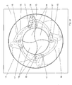
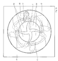
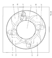
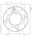
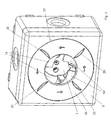
- FIGS. 2a-f an interior view of a front element 6 is shown, so that the components of an integrated closure 13 are visible.
- the closure 13 has a plurality of closure elements 14, which extend in the plane of the front element 6 and are wing-like.
- the closure elements 14 are each arranged to be movable about a fixed bearing 15 and are mechanically coupled in order to ensure a proper sequence of movements during the opening and closing of the closure 13.
- the closure elements 14 are guided in a surrounding guide element 16, wherein pins 17 of the closure elements 14 slide in slot-like grooves 18 of the guide member 16.
- the guide element 16 is annular and dented in some places.
- a prestressed spring 19 acts on the guide element 16 in order to enable a nearly automatic opening or closing of the closure 13 or to secure the opening position after a first movement pulse.
- an opening cycle of the shutter 13 is to be followed.
- a nearly flush surface between front element 6 and closure 13 is formed.
- the closure elements 14 guided by the guide element 16 move uniformly radially outward relative to the center of the front element 6 and release the socket 7 so that a device plug 8 is inserted can be.
- the proper movement of the closure elements 14 ensures the surrounding guide element 16, wherein the pins 17 of the closure elements 14 slide in the grooves 18.
- a nearly flush surface is created between the front element 6 and the closure 13.
- the closure elements 14 are located completely peripherally in the front element 6 and radially surround the sockets 7.
- FIG. 3 an embodiment of a surface-mounted installation is shown, in which case in particular handling elements 20 are visible, which allow a front-side manual movement of the closure 13.
- Other embodiments not shown arise in particular by automatic mechanisms that drive the closure 13 at a central location, for example via a gear in conjunction with the guide member 16.
Landscapes
- Connector Housings Or Holding Contact Members (AREA)
- Details Of Connecting Devices For Male And Female Coupling (AREA)
- Operating, Guiding And Securing Of Roll- Type Closing Members (AREA)
- Casings For Electric Apparatus (AREA)
Abstract
Die Erfindung betrifft ein Installationsgerät (1) bestehend aus einem Gerätesockel (4) und aus einem an dem Gerätesockel (4) befestigten Tragrahmen (5), wobei an einer Rückseite des Gerätesockels (4) Leitungen (12) anschließbar sind und wobei an einer Frontseite des Gerätesockels (4) ein Frontelement (6) befestigt ist. Um ein Installationsgerät (1) zu schaffen, das verschließbar und flachbauend ausgebildet ist, ist in das Frontelement (6) ein Verschluss (13) integriert, der in der Ebene des Frontelementes (6) bewegbar ist.The invention relates to an installation device (1) consisting of a device base (4) and one of the device base (4) attached to the support frame (5), wherein at a rear side of the device base (4) lines (12) are connectable and wherein on a front side of the device base (4) a front element (6) is fixed. In order to create an installation device (1) which is designed to be lockable and flat, a closure (13) is integrated into the front element (6) and can be moved in the plane of the front element (6).
Description
Die Erfindung betrifft ein elektrisches Installationsgerät nach dem Oberbegriff des Patentanspruches 1.The invention relates to an electrical installation device according to the preamble of claim 1.
Elektrische Installationsgeräte in Form von Steckdosen werden im Rahmen der Gebäudeinstallationstechnik eingesetzt und in der Regel ortsfest montiert. In Abhängigkeit von dem Einsatzgebiet und -zweck werden diese Steckdosen oftmals mit Deckeln versehen, um das Eindringen von Fremdkörpern zu vermeiden und darüber hinaus auch um einen unberechtigten Zugriff zu verhindern.Electrical installation devices in the form of sockets are used as part of the building installation technology and usually mounted stationary. Depending on the application and purpose of these sockets are often provided with lids to prevent the ingress of foreign bodies and also to prevent unauthorized access.
Aus dem Stand der Technik sind vielfältige Lösungen bekannt, um mit einem Deckel die Öffnung des Steckdosentopfes zu verschließen. Aus der
Nachteilig ist bei diesen Lösungen, dass die Deckel sowohl in der Verschlussposition als auch in der Öffnungsposition über die übrigen Bauteile des Installationsgerätes, beispielsweise der Zentralplatte oder dem Rahmen, vorstehen. Allgemein besteht das Bedürfnis eine verschließbare aber möglichst flache Baueinheit zu haben, wobei insbesondere im Wohnbereich zusätzlich optisch ansprechende Lösungen erwünscht sind.A disadvantage of these solutions, that the lid both in the closed position and in the open position on the other components of the installation device, such as the central plate or the frame protrude. Generally, there is a need to have a closable but flat as possible unit, especially in the living area additionally visually appealing solutions are desired.
Die Aufgabe der vorliegenden Erfindung besteht deshalb darin, die vorstehend genannten Nachteile zu beseitigen und ein Installationsgerät zu schaffen, das verschließbar und flachbauend ausgebildet ist.The object of the present invention is therefore to eliminate the above-mentioned disadvantages and to provide an installation device which is formed lockable and flat construction.
Gelöst wird diese Aufgabe durch die im Patentanspruch 1 angegebenen Merkmale. Vorteilhafte Ausgestaltungen ergeben sich aus den Unteransprüchen.This problem is solved by the features specified in claim 1. Advantageous embodiments emerge from the subclaims.
Die Erfindung gemäß dem Patentanspruch 1 weist ein Installationsgerät mit einem Verschluss auf, der in ein Frontelement integriert ist und damit flachbauend ausgebildet ist. Im geschlossenen Zustand entsteht eine nahezu flächenbündige Oberfläche zwischen Frontelement und Verschluss. Der Verschluss öffnet und schließt in der Ebene des Frontelementes. Verschlusselemente sind randseitig in dem Frontelement gelagert und geführt und umgeben radial einen mittleren Bereich, vorzugsweise einen Steckdosentopf. Es wird kein zusätzlicher Platz vor oder hinter dem Frontelement benötigt. Vielmehr wird der Verschluss durch Optimierung des Raumes und der Bauteilanordnung in die vorhandene Struktur integriert.The invention according to claim 1 has an installation device with a closure which is integrated in a front element and thus formed flat construction. When closed, a nearly flush surface is created between the front element and the closure. The shutter opens and closes in the plane of the front element. Closure elements are mounted and guided on the edge side in the front element and radially surround a central region, preferably a socket pot. No additional space is required in front of or behind the front element. Rather, the closure is integrated by optimizing the space and the component assembly in the existing structure.
Der Verschluss weist mehrere Verschlusselemente auf, die sich in der Ebene des Frontelementes erstrecken und jeweils um ein Festlager bewegbar angeordnet sind. Dabei bewegen sich die Verschlusselemente radial ein- oder auswärts gegenüber dem Mittelpunkt des Frontelementes. Die einzelnen Verschlusselemente sind mechanisch gekoppelt, um einen ordnungsgemäßen Bewegungsablauf der Verschlusselemente beim Öffnen und Schließen des Verschlusses zu gewährleisten. Vorzugsweise sind die Verschlusselemente hierzu in einem sie umgebenden Führungselement geführt, wobei Zapfen der Verschlusselemente in kulissenartigen Nuten des Führungselementes gleiten.The closure has a plurality of closure elements which extend in the plane of the front element and are each arranged to be movable about a fixed bearing. In this case, the closure elements move radially inward or outward relative to the center of the front element. The individual closure elements are mechanically coupled to ensure a proper movement of the closure elements when opening and closing the closure. For this purpose, the closure elements are preferably guided in a surrounding guide element, wherein pins of the closure elements slide in slot-like grooves of the guide element.
Der Verschluss kann entweder frontseitig direkt durch Handhabungselemente an dem Frontelement bewegt werden oder durch Automatismen, die an einer zentralen Stelle, beispielsweise über ein Getriebe in Verbindung mit dem Führungselement, den Verschluss antreiben. Neben dem manuell zu bedienenden Verschluss existiert eine Ausführung, bei der die Verschlussmechanik mittels eines entsprechend kleinen Elektromotors elektrisch angetrieben wird. Je nach Ausführung lässt sich die Elektrik auf unterschiedliche Weise aktivieren, beispielsweise direkt mittels einer Funktionstaste am Installationsgerät oder fernbedienbar. Denkbar sind hier vor allem drahtlose Funktionalitäten beispielsweise Funk- oder IR-Komponenten. Von Vorteil ist eine sensorische Erfassung sich nähernder Metalle, z. B. der Kontaktstifte eines Gerätesteckers, um hierdurch eine automatische Öffnung des Verschlusses zu bewirken. Darüber hinaus ist auch eine Berechtigungsabfrage möglich, so dass nur mittels spezieller Zugangsparameter, beispielsweise Transpondersignale oder Zahlencodes, eine Öffnung des Verschlusses erfolgt. Praktischerweise existieren deshalb unterschiedlich ausgestattete Frontelemente, die je nach Anwendungsfall einsetzbar sind.The closure can either be moved directly on the front element by means of handling elements on the front element or by means of automatisms which are located at a central location, for example via a Gear in conjunction with the guide element, drive the shutter. In addition to the manually operated closure there is an embodiment in which the closure mechanism is electrically driven by means of a correspondingly small electric motor. Depending on the version, the electrical system can be activated in different ways, for example directly by means of a function key on the installation device or remotely operable. Above all, wireless functionalities, for example radio or IR components, are conceivable here. An advantage is a sensory detection of approaching metals, eg. As the pins of a device plug, thereby causing an automatic opening of the closure. In addition, an authorization query is possible, so that only by means of special access parameters, such as transponder signals or numerical codes, an opening of the shutter takes place. Conveniently, therefore, different equipped front elements that can be used depending on the application.
In einer besonders vorteilhaften Ausführung lassen sich die Frontelemente einschließlich der Verschlusselemente durch entsprechend gestaltete Oberflächen nahtlos an die Oberflächen der Umgebung anpassen und damit integrieren. Denkbar sind auch informative Beschriftungen und Bedruckungen der Verschlusselemente.In a particularly advantageous embodiment, the front elements including the closure elements can be seamlessly adapted to the surfaces of the environment by means of correspondingly designed surfaces and thus integrated. Also conceivable are informative inscriptions and imprints of the closure elements.
Es wird ein universell verwendbares Frontelement geschaffen, mit dem im Bedarfsfall bestehende Installationsgeräte umgerüstet werden können. Wesentlich ist dabei, dass zur Aufrüstung des Installationsgerätes lediglich das gerätespezifische Frontelement ausgetauscht werden muss. Eine Demontage des Gerätesockels bzw. des Tragrahmens ist nicht notwendig. Die vorhandene Geometrie der Gerätesockel kann unverändert genutzt werden, da die Befestigungspunkte und Kontaktpunkte erhalten bleiben.It creates a universally usable front element, with which existing installation equipment can be converted if necessary. It is essential that only the device-specific front element needs to be replaced to upgrade the installation device. A disassembly of the device base or the support frame is not necessary. The existing geometry of the device base can be used unchanged, since the attachment points and contact points are retained.
Weitere Einzelheiten, Merkmale und Vorteile der Erfindung ergeben sich aus nachfolgender Beschreibung eines bevorzugten Ausführungsbeispieles anhand der Zeichnungen.Further details, features and advantages of the invention will become apparent from the following description of a preferred embodiment with reference to the drawings.
- Figur 1FIG. 1
- einen schematischen Aufbau eines Installationsgerätes.a schematic structure of an installation device.
- Figur 2a-fFigure 2a-f
- schematisch den Aufbau eines Frontelementes des Installationsgerätes und einen Öffnungszyklus eines Verschlusses.schematically the structure of a front element of the installation device and an opening cycle of a closure.
- Figur 3FIG. 3
- eine perspektivische Ansicht einer Aufputzanordnung mit halb geöffnetem Verschluss und Handhabungselementen.a perspective view of a surface-mounted arrangement with half-open shutter and handling elements.
Gleiche oder gleichwirkende Bauteile sind in der nachfolgenden Beschreibung mit gleichen Bezugszeichen versehen.The same or equivalent components are provided in the following description with the same reference numerals.
Nachfolgend wird der Aufbau und die Funktionsweise des erfindungsgemäßen Installationsgerätes 1 näher beschrieben. Beispielhaft ist dabei ein Installationsgerät 1 in Form einer Steckdose dargestellt, die in einem Installationsgehäuse 2 befestigt ist, welches ortsfest in einer Gebäudewand 3 fixiert ist. Die Steckdose 1 weist einen Gerätesockel 4 auf, den außenseitig ein Tragrahmen 5 umgibt, der die Befestigung der Steckdose 1 in dem Installationsgehäuse 2 ermöglicht. Frontseitig ist ein Frontelement 6 befestigt, in dem ein Aufnahmeraum 7 für einen Gerätestecker 8 ausgebildet ist und das je nach Anwendung ein- oder mehrteilig sein kann. In dem Gerätesockel 4 sind Anschlussklemmen 9 und damit verbundene metallische Kontaktelemente angeordnet, in die frontseitig Anschlusskontakte 10 des Gerätesteckers 8 gesteckt werden. Des weiteren ist in dem Gerätesockel 4 ein nicht dargestellter Erdungsbügel angeordnet, der zur frontseitigen Kontaktierung eines Erdungskontaktes des Gerätesteckers 8 dient. Eine wandseitig verlegte Versorgungsleitung 11 versorgt die Steckdose 1 mit einer Netzspannung, wobei die einzelnen Leitungen 12 lösbar in den Anschlussklemmen 9 fixiert sind. (
In den
Anhand der
In
Die vorstehende Beschreibung des Ausführungsbeispieles dient nur zu illustrativen Zwecken und nicht zum Zwecke der Beschränkung der Erfindung. Im Rahmen der Erfindung sind verschiedene Änderungen und Modifikationen möglich, ohne den Umfang der Erfindung sowie ihrer Äquivalente zu verlassen.The foregoing description of the embodiment is for illustrative purposes only and not for the purpose of limiting the invention. Various changes and modifications are possible within the scope of the invention without departing from the scope of the invention and its equivalents.
- 11
- Installationsgerätinstallation device
- 22
- Installationsgehäuseinstallation Enclosures
- 33
- Gebäudewandbuilding wall
- 44
- Gerätesockeldevice base
- 55
- Tragrahmensupporting frame
- 66
- Frontelementfront element
- 77
- Aufnahmeraum (Steckdosentopf)Recording room (socket pot)
- 88th
- Gerätesteckerconnectors
- 99
- Anschlussklemmenterminals
- 1010
- Anschlusskontakteterminals
- 1111
- Versorgungsleitungsupply line
- 1212
- Leitungencables
- 1313
- Verschlussshutter
- 1414
- Verschlusselementclosure element
- 1515
- Festlagerfixed bearing
- 1616
- Führungselementguide element
- 1717
- Zapfenspigot
- 1818
- Nutgroove
- 1919
- Federfeather
- 2020
- Handhabungselementehandling elements
Claims (13)
Applications Claiming Priority (1)
| Application Number | Priority Date | Filing Date | Title |
|---|---|---|---|
| DE102007063585A DE102007063585B4 (en) | 2007-12-29 | 2007-12-29 | Electrical installation device |
Publications (3)
| Publication Number | Publication Date |
|---|---|
| EP2075889A2 true EP2075889A2 (en) | 2009-07-01 |
| EP2075889A3 EP2075889A3 (en) | 2011-04-13 |
| EP2075889B1 EP2075889B1 (en) | 2016-08-24 |
Family
ID=40548840
Family Applications (1)
| Application Number | Title | Priority Date | Filing Date |
|---|---|---|---|
| EP08021986.8A Not-in-force EP2075889B1 (en) | 2007-12-29 | 2008-12-18 | Electric installation device |
Country Status (4)
| Country | Link |
|---|---|
| EP (1) | EP2075889B1 (en) |
| DE (1) | DE102007063585B4 (en) |
| DK (1) | DK2075889T3 (en) |
| ES (1) | ES2603224T3 (en) |
Cited By (7)
| Publication number | Priority date | Publication date | Assignee | Title |
|---|---|---|---|---|
| WO2011051150A1 (en) * | 2009-10-28 | 2011-05-05 | Amad Mennekes Holding Gmbh & Co. Kg | Plug device having a closure unit |
| CN102347549A (en) * | 2010-07-21 | 2012-02-08 | 施耐德电器工业公司 | Tamper-proof socket outlet assembly |
| WO2012123265A1 (en) * | 2011-03-16 | 2012-09-20 | Amad Mennekes Holding Gmbh & Co. Kg | Electrical plug-in device comprising a closure unit |
| EP2685568A1 (en) * | 2012-06-14 | 2014-01-15 | Scame Parre S.p.A. | Industrial socket with live contacts protection device |
| EP3772605A1 (en) * | 2019-08-05 | 2021-02-10 | KÖRA-PACKMAT Maschinenbau GmbH | Sealing device for a gas-conveying conduit |
| CN113508500A (en) * | 2018-12-13 | 2021-10-15 | 汉斯-彼得·弗兰克 | Mounting elements for socket elements |
| CN115031028A (en) * | 2022-07-07 | 2022-09-09 | 安徽汉威环境科技有限公司 | Rotary closing gate |
Families Citing this family (14)
| Publication number | Priority date | Publication date | Assignee | Title |
|---|---|---|---|---|
| DE102012025533B4 (en) | 2011-12-22 | 2014-12-24 | Bachmann Technology GmbH & Co. KG | installation housing |
| DE102013000829B4 (en) * | 2013-01-18 | 2015-03-12 | Maximilian Rüttiger | Grommet |
| CN105351545B (en) * | 2015-12-09 | 2017-12-22 | 长沙盛泓机械有限公司 | The circular baiting valve of Daqu production line |
| DE102019128509A1 (en) * | 2019-10-22 | 2021-04-22 | Volkswagen Aktiengesellschaft | Locking system for a high-voltage connection |
| DE102020002945B3 (en) | 2020-05-18 | 2021-07-29 | Berthold Kalkus | Installation element |
| EP4264762A1 (en) | 2020-12-21 | 2023-10-25 | Bachmann GmbH | Installation housing and method for operating an installation housing |
| DE102021106039A1 (en) | 2020-12-21 | 2022-06-23 | Bachmann Gmbh | built-in housing; Procedure for operating an installation housing |
| DE112022000985A5 (en) | 2021-02-08 | 2024-02-08 | Bachmann Gmbh | CAN CASES; METHOD FOR OPERATING A CAN HOUSING |
| WO2022167039A1 (en) | 2021-02-08 | 2022-08-11 | Bachmann Gmbh | Socket housing, method for operating a socket housing |
| DE102021106042A1 (en) | 2021-02-08 | 2022-08-11 | Bachmann Gmbh | can housing; Method of operating a can body |
| DE102021106043A1 (en) | 2021-02-08 | 2022-08-11 | Bachmann Gmbh | can housing; Method of operating a can housing |
| DE102021107848B4 (en) | 2021-03-29 | 2026-01-22 | Bachmann Gmbh | Can housing; method for operating a can housing |
| EP4550598A1 (en) | 2023-10-31 | 2025-05-07 | Bachmann GmbH | Can housing; method for operating a can housing |
| DE102024115508B4 (en) * | 2023-10-31 | 2025-08-21 | Bachmann Gmbh | Can housing; method for operating a can housing |
Citations (1)
| Publication number | Priority date | Publication date | Assignee | Title |
|---|---|---|---|---|
| EP0786833B1 (en) | 1996-01-29 | 2003-04-16 | Dehn + Söhne Gmbh + Co. Kg | Socket with an additionally function modul |
Family Cites Families (14)
| Publication number | Priority date | Publication date | Assignee | Title |
|---|---|---|---|---|
| DE429630C (en) * | 1924-09-25 | 1926-05-31 | Friedrich Breitlaender | Incandescent lamp socket with extended socket casing to protect against contact with live parts |
| DE1837279U (en) * | 1961-02-24 | 1961-09-07 | Kurt Rath | ELECTRIC FAN USED FOR VENTILATION OF CLOSED ROOMS. |
| DE2060966A1 (en) * | 1970-12-11 | 1972-06-29 | Bbc Brown Boveri & Cie | Electrical installation device with cover |
| US4217019A (en) * | 1976-11-19 | 1980-08-12 | Bunker Ramo Corporation | EMI protected connector assembly |
| DE8708617U1 (en) * | 1987-06-20 | 1987-09-03 | Spiegeler, Jakob, 5630 Remscheid | Safety socket |
| RU2109192C1 (en) * | 1996-03-21 | 1998-04-20 | Александр Леонидович Кузьмин | Shutoff device |
| DE19631496A1 (en) * | 1996-08-03 | 1998-02-05 | Merten Gmbh & Co Kg Geb | Electrical socket with child lock |
| US6050834A (en) * | 1998-12-21 | 2000-04-18 | The United States Of America As Represented By The Secretary Of The Navy | Electrical outlet splash protector |
| DE10155502A1 (en) * | 2001-11-13 | 2003-05-22 | Abb Patent Gmbh | Electrical installation device with sliding cover |
| KR200276531Y1 (en) * | 2002-03-08 | 2002-05-24 | 이덕현 | Safty device of an electric outlet |
| US6545218B1 (en) * | 2002-05-14 | 2003-04-08 | Donald J. Blaess | Safety cover for dual electrical wall mounted outlets |
| DE10246654B3 (en) * | 2002-10-07 | 2004-04-15 | Chao-Chi Wang | Electrical plug socket with rotatable protective cover spring biased into closed position for preventing ingress of dirt and moisture |
| US7438567B2 (en) * | 2004-12-28 | 2008-10-21 | Belkin International Inc. | Safety mechanism, electrical outlet containing same, and method of manufacturing same |
| DE102006058894A1 (en) * | 2005-12-21 | 2007-06-28 | Bachmann Gmbh & Co. Kg | Cover for connection box, has closing parts continuously movable from closing position which covers bush, to opening position which releases bush by opening and releasing common opening in its opening position |
-
2007
- 2007-12-29 DE DE102007063585A patent/DE102007063585B4/en not_active Expired - Fee Related
-
2008
- 2008-12-18 DK DK08021986.8T patent/DK2075889T3/en active
- 2008-12-18 EP EP08021986.8A patent/EP2075889B1/en not_active Not-in-force
- 2008-12-18 ES ES08021986.8T patent/ES2603224T3/en active Active
Patent Citations (1)
| Publication number | Priority date | Publication date | Assignee | Title |
|---|---|---|---|---|
| EP0786833B1 (en) | 1996-01-29 | 2003-04-16 | Dehn + Söhne Gmbh + Co. Kg | Socket with an additionally function modul |
Cited By (16)
| Publication number | Priority date | Publication date | Assignee | Title |
|---|---|---|---|---|
| WO2011051150A1 (en) * | 2009-10-28 | 2011-05-05 | Amad Mennekes Holding Gmbh & Co. Kg | Plug device having a closure unit |
| US8523599B2 (en) | 2009-10-28 | 2013-09-03 | Amad Mennekes Holding Gmbh & Co. Kg | Plug device having a closure unit |
| CN102347549A (en) * | 2010-07-21 | 2012-02-08 | 施耐德电器工业公司 | Tamper-proof socket outlet assembly |
| CN102347549B (en) * | 2010-07-21 | 2016-01-20 | 施耐德电器工业公司 | Socket outlet assembly |
| EP2410625A3 (en) * | 2010-07-21 | 2013-07-17 | Schneider Electric Industries SAS | Tamper-proof socket outlet assembly |
| RU2546961C1 (en) * | 2011-03-16 | 2015-04-10 | Амад Меннекес Холдинг Гмбх Унд Ко. Кг | Electric plugging device, control gate (versions) and electric plugging device control method |
| US8845345B2 (en) | 2011-03-16 | 2014-09-30 | Amad Mennekes Holding Gmbh & Co. Kg | Electrical plug-in device with closure device |
| CN103503241A (en) * | 2011-03-16 | 2014-01-08 | Amad曼奈柯斯控股有限责任两合公司 | Electrical plug-in device comprising a closure unit |
| WO2012123265A1 (en) * | 2011-03-16 | 2012-09-20 | Amad Mennekes Holding Gmbh & Co. Kg | Electrical plug-in device comprising a closure unit |
| CN103503241B (en) * | 2011-03-16 | 2016-08-17 | Amad曼奈柯斯控股有限责任两合公司 | Electrical plug-in devices with locking devices |
| US9431748B2 (en) | 2011-03-16 | 2016-08-30 | Amad Mennekes Holding Gmbh & Co. Kg | Electrical plug-in connector with closure device |
| EP2685568A1 (en) * | 2012-06-14 | 2014-01-15 | Scame Parre S.p.A. | Industrial socket with live contacts protection device |
| CN113508500A (en) * | 2018-12-13 | 2021-10-15 | 汉斯-彼得·弗兰克 | Mounting elements for socket elements |
| EP3772605A1 (en) * | 2019-08-05 | 2021-02-10 | KÖRA-PACKMAT Maschinenbau GmbH | Sealing device for a gas-conveying conduit |
| US11353119B2 (en) | 2019-08-05 | 2022-06-07 | Köra-Packmat Maschinenbau GmbH | Closing device for a gas-conducting conduit |
| CN115031028A (en) * | 2022-07-07 | 2022-09-09 | 安徽汉威环境科技有限公司 | Rotary closing gate |
Also Published As
| Publication number | Publication date |
|---|---|
| ES2603224T3 (en) | 2017-02-24 |
| DE102007063585A1 (en) | 2009-07-09 |
| DK2075889T3 (en) | 2016-12-05 |
| DE102007063585B4 (en) | 2012-08-09 |
| EP2075889B1 (en) | 2016-08-24 |
| EP2075889A3 (en) | 2011-04-13 |
Similar Documents
| Publication | Publication Date | Title |
|---|---|---|
| EP2075889B1 (en) | Electric installation device | |
| DE102010041314A1 (en) | Charging devices for charging battery of electric car, have drive unit electrically interconnecting devices and/or locking or unlocking mechanical linkage between devices, where mechanical linkage is latched by lever | |
| EP2368295A1 (en) | Closure system for a power outlet | |
| DE29818023U1 (en) | Device for winding and unwinding a curtain | |
| DE102008057588A1 (en) | Electric device | |
| DE102008064442A1 (en) | Electrical installation device i.e. plug socket, for use during building construction, has locking device that is integrated into front element and lockably and/or releasably movable in plane of front element to receiving area | |
| EP1837957A2 (en) | Bayonet lock with self contact | |
| DE102019209521B4 (en) | User interface device | |
| DE102010054372A1 (en) | Outside mirror arrangement with sliding disk | |
| EP3710661B1 (en) | Modular drive device | |
| DE202016006336U1 (en) | Device for switching and / or power supply for mobile installations | |
| DE102007063584A1 (en) | Electrical installation device for use in building installation engineering, has cylindrical module comprising circular segment shaped base area and mounted at front side in receiving space of socket | |
| EP2633594B1 (en) | Wall insert | |
| EP2223392B1 (en) | Electrical installation device | |
| EP1797261B1 (en) | Device for actuating a lock in a vehicle | |
| DE102016002739A1 (en) | Wall bracket for electronic components | |
| DE102024115508B4 (en) | Can housing; method for operating a can housing | |
| DE202006001398U1 (en) | Current adaptor with multiple angle current connection possibilities has a moveable base with two moveable contact points for connection with fixed contact points | |
| WO2019011378A1 (en) | LED PANEL WITH SWITCHABLE CONNECTOR | |
| EP2568851A1 (en) | Securing apparatus for furniture drive | |
| EP4550598A1 (en) | Can housing; method for operating a can housing | |
| EP3913178A1 (en) | Lifting and sliding door system and method for installing a sliding door | |
| EP2202851B1 (en) | Socket with release mechanism | |
| EP4258307A1 (en) | Apparatus for home installation technology | |
| EP4545346A1 (en) | Charging station for electric vehicles |
Legal Events
| Date | Code | Title | Description |
|---|---|---|---|
| PUAI | Public reference made under article 153(3) epc to a published international application that has entered the european phase |
Free format text: ORIGINAL CODE: 0009012 |
|
| AK | Designated contracting states |
Kind code of ref document: A2 Designated state(s): AT BE BG CH CY CZ DE DK EE ES FI FR GB GR HR HU IE IS IT LI LT LU LV MC MT NL NO PL PT RO SE SI SK TR |
|
| AX | Request for extension of the european patent |
Extension state: AL BA MK RS |
|
| PUAL | Search report despatched |
Free format text: ORIGINAL CODE: 0009013 |
|
| AK | Designated contracting states |
Kind code of ref document: A3 Designated state(s): AT BE BG CH CY CZ DE DK EE ES FI FR GB GR HR HU IE IS IT LI LT LU LV MC MT NL NO PL PT RO SE SI SK TR |
|
| AX | Request for extension of the european patent |
Extension state: AL BA MK RS |
|
| RIC1 | Information provided on ipc code assigned before grant |
Ipc: F16K 3/03 20060101ALI20110309BHEP Ipc: H02G 3/14 20060101ALI20110309BHEP Ipc: H01R 13/453 20060101AFI20110309BHEP Ipc: H01R 24/00 20110101ALI20110309BHEP |
|
| 17P | Request for examination filed |
Effective date: 20110926 |
|
| AKX | Designation fees paid |
Designated state(s): AT BE BG CH CY CZ DE DK EE ES FI FR GB GR HR HU IE IS IT LI LT LU LV MC MT NL NO PL PT RO SE SI SK TR |
|
| 17Q | First examination report despatched |
Effective date: 20140527 |
|
| REG | Reference to a national code |
Ref country code: DE Ref legal event code: R079 Ref document number: 502008014549 Country of ref document: DE Free format text: PREVIOUS MAIN CLASS: H02G0003140000 Ipc: H01R0013453000 |
|
| GRAP | Despatch of communication of intention to grant a patent |
Free format text: ORIGINAL CODE: EPIDOSNIGR1 |
|
| RIC1 | Information provided on ipc code assigned before grant |
Ipc: H01R 24/00 20110101ALI20160304BHEP Ipc: H01R 24/78 20110101ALI20160304BHEP Ipc: H01R 13/453 20060101AFI20160304BHEP Ipc: H02G 3/14 20060101ALI20160304BHEP Ipc: F16K 3/03 20060101ALI20160304BHEP Ipc: H01R 103/00 20060101ALI20160304BHEP Ipc: H01R 13/447 20060101ALI20160304BHEP |
|
| INTG | Intention to grant announced |
Effective date: 20160323 |
|
| GRAS | Grant fee paid |
Free format text: ORIGINAL CODE: EPIDOSNIGR3 |
|
| GRAA | (expected) grant |
Free format text: ORIGINAL CODE: 0009210 |
|
| AK | Designated contracting states |
Kind code of ref document: B1 Designated state(s): AT BE BG CH CY CZ DE DK EE ES FI FR GB GR HR HU IE IS IT LI LT LU LV MC MT NL NO PL PT RO SE SI SK TR |
|
| RAP1 | Party data changed (applicant data changed or rights of an application transferred) |
Owner name: MERTEN GMBH |
|
| REG | Reference to a national code |
Ref country code: GB Ref legal event code: FG4D Free format text: NOT ENGLISH |
|
| REG | Reference to a national code |
Ref country code: CH Ref legal event code: EP |
|
| REG | Reference to a national code |
Ref country code: AT Ref legal event code: REF Ref document number: 823817 Country of ref document: AT Kind code of ref document: T Effective date: 20160915 |
|
| REG | Reference to a national code |
Ref country code: IE Ref legal event code: FG4D Free format text: LANGUAGE OF EP DOCUMENT: GERMAN |
|
| REG | Reference to a national code |
Ref country code: DE Ref legal event code: R096 Ref document number: 502008014549 Country of ref document: DE |
|
| REG | Reference to a national code |
Ref country code: FR Ref legal event code: PLFP Year of fee payment: 9 |
|
| REG | Reference to a national code |
Ref country code: DK Ref legal event code: T3 Effective date: 20161129 |
|
| REG | Reference to a national code |
Ref country code: SE Ref legal event code: TRGR |
|
| REG | Reference to a national code |
Ref country code: LT Ref legal event code: MG4D |
|
| REG | Reference to a national code |
Ref country code: NL Ref legal event code: MP Effective date: 20160824 |
|
| PG25 | Lapsed in a contracting state [announced via postgrant information from national office to epo] |
Ref country code: HR Free format text: LAPSE BECAUSE OF FAILURE TO SUBMIT A TRANSLATION OF THE DESCRIPTION OR TO PAY THE FEE WITHIN THE PRESCRIBED TIME-LIMIT Effective date: 20160824 Ref country code: NL Free format text: LAPSE BECAUSE OF FAILURE TO SUBMIT A TRANSLATION OF THE DESCRIPTION OR TO PAY THE FEE WITHIN THE PRESCRIBED TIME-LIMIT Effective date: 20160824 Ref country code: FI Free format text: LAPSE BECAUSE OF FAILURE TO SUBMIT A TRANSLATION OF THE DESCRIPTION OR TO PAY THE FEE WITHIN THE PRESCRIBED TIME-LIMIT Effective date: 20160824 Ref country code: NO Free format text: LAPSE BECAUSE OF FAILURE TO SUBMIT A TRANSLATION OF THE DESCRIPTION OR TO PAY THE FEE WITHIN THE PRESCRIBED TIME-LIMIT Effective date: 20161124 Ref country code: LT Free format text: LAPSE BECAUSE OF FAILURE TO SUBMIT A TRANSLATION OF THE DESCRIPTION OR TO PAY THE FEE WITHIN THE PRESCRIBED TIME-LIMIT Effective date: 20160824 Ref country code: IT Free format text: LAPSE BECAUSE OF FAILURE TO SUBMIT A TRANSLATION OF THE DESCRIPTION OR TO PAY THE FEE WITHIN THE PRESCRIBED TIME-LIMIT Effective date: 20160824 |
|
| PGFP | Annual fee paid to national office [announced via postgrant information from national office to epo] |
Ref country code: DE Payment date: 20161213 Year of fee payment: 9 |
|
| REG | Reference to a national code |
Ref country code: ES Ref legal event code: FG2A Ref document number: 2603224 Country of ref document: ES Kind code of ref document: T3 Effective date: 20170224 |
|
| PG25 | Lapsed in a contracting state [announced via postgrant information from national office to epo] |
Ref country code: LV Free format text: LAPSE BECAUSE OF FAILURE TO SUBMIT A TRANSLATION OF THE DESCRIPTION OR TO PAY THE FEE WITHIN THE PRESCRIBED TIME-LIMIT Effective date: 20160824 Ref country code: GR Free format text: LAPSE BECAUSE OF FAILURE TO SUBMIT A TRANSLATION OF THE DESCRIPTION OR TO PAY THE FEE WITHIN THE PRESCRIBED TIME-LIMIT Effective date: 20161125 Ref country code: PT Free format text: LAPSE BECAUSE OF FAILURE TO SUBMIT A TRANSLATION OF THE DESCRIPTION OR TO PAY THE FEE WITHIN THE PRESCRIBED TIME-LIMIT Effective date: 20161226 |
|
| PG25 | Lapsed in a contracting state [announced via postgrant information from national office to epo] |
Ref country code: EE Free format text: LAPSE BECAUSE OF FAILURE TO SUBMIT A TRANSLATION OF THE DESCRIPTION OR TO PAY THE FEE WITHIN THE PRESCRIBED TIME-LIMIT Effective date: 20160824 Ref country code: RO Free format text: LAPSE BECAUSE OF FAILURE TO SUBMIT A TRANSLATION OF THE DESCRIPTION OR TO PAY THE FEE WITHIN THE PRESCRIBED TIME-LIMIT Effective date: 20160824 |
|
| REG | Reference to a national code |
Ref country code: DE Ref legal event code: R097 Ref document number: 502008014549 Country of ref document: DE |
|
| PG25 | Lapsed in a contracting state [announced via postgrant information from national office to epo] |
Ref country code: CZ Free format text: LAPSE BECAUSE OF FAILURE TO SUBMIT A TRANSLATION OF THE DESCRIPTION OR TO PAY THE FEE WITHIN THE PRESCRIBED TIME-LIMIT Effective date: 20160824 Ref country code: SK Free format text: LAPSE BECAUSE OF FAILURE TO SUBMIT A TRANSLATION OF THE DESCRIPTION OR TO PAY THE FEE WITHIN THE PRESCRIBED TIME-LIMIT Effective date: 20160824 Ref country code: PL Free format text: LAPSE BECAUSE OF FAILURE TO SUBMIT A TRANSLATION OF THE DESCRIPTION OR TO PAY THE FEE WITHIN THE PRESCRIBED TIME-LIMIT Effective date: 20160824 Ref country code: BE Free format text: LAPSE BECAUSE OF NON-PAYMENT OF DUE FEES Effective date: 20161231 Ref country code: BG Free format text: LAPSE BECAUSE OF FAILURE TO SUBMIT A TRANSLATION OF THE DESCRIPTION OR TO PAY THE FEE WITHIN THE PRESCRIBED TIME-LIMIT Effective date: 20161124 |
|
| PLBE | No opposition filed within time limit |
Free format text: ORIGINAL CODE: 0009261 |
|
| STAA | Information on the status of an ep patent application or granted ep patent |
Free format text: STATUS: NO OPPOSITION FILED WITHIN TIME LIMIT |
|
| REG | Reference to a national code |
Ref country code: CH Ref legal event code: PL |
|
| 26N | No opposition filed |
Effective date: 20170526 |
|
| PG25 | Lapsed in a contracting state [announced via postgrant information from national office to epo] |
Ref country code: SI Free format text: LAPSE BECAUSE OF FAILURE TO SUBMIT A TRANSLATION OF THE DESCRIPTION OR TO PAY THE FEE WITHIN THE PRESCRIBED TIME-LIMIT Effective date: 20160824 |
|
| PG25 | Lapsed in a contracting state [announced via postgrant information from national office to epo] |
Ref country code: MC Free format text: LAPSE BECAUSE OF FAILURE TO SUBMIT A TRANSLATION OF THE DESCRIPTION OR TO PAY THE FEE WITHIN THE PRESCRIBED TIME-LIMIT Effective date: 20160824 |
|
| REG | Reference to a national code |
Ref country code: IE Ref legal event code: MM4A |
|
| PG25 | Lapsed in a contracting state [announced via postgrant information from national office to epo] |
Ref country code: LI Free format text: LAPSE BECAUSE OF NON-PAYMENT OF DUE FEES Effective date: 20161231 Ref country code: CH Free format text: LAPSE BECAUSE OF NON-PAYMENT OF DUE FEES Effective date: 20161231 Ref country code: LU Free format text: LAPSE BECAUSE OF NON-PAYMENT OF DUE FEES Effective date: 20161218 |
|
| REG | Reference to a national code |
Ref country code: FR Ref legal event code: PLFP Year of fee payment: 10 |
|
| PG25 | Lapsed in a contracting state [announced via postgrant information from national office to epo] |
Ref country code: IE Free format text: LAPSE BECAUSE OF NON-PAYMENT OF DUE FEES Effective date: 20161218 |
|
| REG | Reference to a national code |
Ref country code: BE Ref legal event code: MM Effective date: 20161231 |
|
| REG | Reference to a national code |
Ref country code: AT Ref legal event code: MM01 Ref document number: 823817 Country of ref document: AT Kind code of ref document: T Effective date: 20161218 |
|
| PG25 | Lapsed in a contracting state [announced via postgrant information from national office to epo] |
Ref country code: AT Free format text: LAPSE BECAUSE OF NON-PAYMENT OF DUE FEES Effective date: 20161218 Ref country code: CY Free format text: LAPSE BECAUSE OF FAILURE TO SUBMIT A TRANSLATION OF THE DESCRIPTION OR TO PAY THE FEE WITHIN THE PRESCRIBED TIME-LIMIT Effective date: 20160824 Ref country code: HU Free format text: LAPSE BECAUSE OF FAILURE TO SUBMIT A TRANSLATION OF THE DESCRIPTION OR TO PAY THE FEE WITHIN THE PRESCRIBED TIME-LIMIT; INVALID AB INITIO Effective date: 20081218 |
|
| PG25 | Lapsed in a contracting state [announced via postgrant information from national office to epo] |
Ref country code: IS Free format text: LAPSE BECAUSE OF FAILURE TO SUBMIT A TRANSLATION OF THE DESCRIPTION OR TO PAY THE FEE WITHIN THE PRESCRIBED TIME-LIMIT Effective date: 20160824 Ref country code: TR Free format text: LAPSE BECAUSE OF FAILURE TO SUBMIT A TRANSLATION OF THE DESCRIPTION OR TO PAY THE FEE WITHIN THE PRESCRIBED TIME-LIMIT Effective date: 20160824 |
|
| REG | Reference to a national code |
Ref country code: DE Ref legal event code: R119 Ref document number: 502008014549 Country of ref document: DE |
|
| PG25 | Lapsed in a contracting state [announced via postgrant information from national office to epo] |
Ref country code: MT Free format text: LAPSE BECAUSE OF FAILURE TO SUBMIT A TRANSLATION OF THE DESCRIPTION OR TO PAY THE FEE WITHIN THE PRESCRIBED TIME-LIMIT Effective date: 20160824 |
|
| PG25 | Lapsed in a contracting state [announced via postgrant information from national office to epo] |
Ref country code: DE Free format text: LAPSE BECAUSE OF NON-PAYMENT OF DUE FEES Effective date: 20180703 |
|
| PGFP | Annual fee paid to national office [announced via postgrant information from national office to epo] |
Ref country code: GB Payment date: 20231102 Year of fee payment: 16 |
|
| PGFP | Annual fee paid to national office [announced via postgrant information from national office to epo] |
Ref country code: SE Payment date: 20231110 Year of fee payment: 16 Ref country code: FR Payment date: 20231108 Year of fee payment: 16 Ref country code: DK Payment date: 20231215 Year of fee payment: 16 |
|
| PGFP | Annual fee paid to national office [announced via postgrant information from national office to epo] |
Ref country code: ES Payment date: 20240111 Year of fee payment: 16 |
|
| REG | Reference to a national code |
Ref country code: DK Ref legal event code: EBP Effective date: 20241231 |
|
| REG | Reference to a national code |
Ref country code: SE Ref legal event code: EUG |
|
| GBPC | Gb: european patent ceased through non-payment of renewal fee |
Effective date: 20241218 |
|
| PG25 | Lapsed in a contracting state [announced via postgrant information from national office to epo] |
Ref country code: GB Free format text: LAPSE BECAUSE OF NON-PAYMENT OF DUE FEES Effective date: 20241218 |
|
| PG25 | Lapsed in a contracting state [announced via postgrant information from national office to epo] |
Ref country code: FR Free format text: LAPSE BECAUSE OF NON-PAYMENT OF DUE FEES Effective date: 20241231 |
|
| PG25 | Lapsed in a contracting state [announced via postgrant information from national office to epo] |
Ref country code: DK Free format text: LAPSE BECAUSE OF NON-PAYMENT OF DUE FEES Effective date: 20241231 |
|
| REG | Reference to a national code |
Ref country code: ES Ref legal event code: FD2A Effective date: 20260130 |