EP0786047B1 - Vorrichtung mit kraftstoffeinspritzung und schmiermittelfördereinrichtung für verbrennungsmotoren - Google Patents
Vorrichtung mit kraftstoffeinspritzung und schmiermittelfördereinrichtung für verbrennungsmotoren Download PDFInfo
- Publication number
- EP0786047B1 EP0786047B1 EP96927669A EP96927669A EP0786047B1 EP 0786047 B1 EP0786047 B1 EP 0786047B1 EP 96927669 A EP96927669 A EP 96927669A EP 96927669 A EP96927669 A EP 96927669A EP 0786047 B1 EP0786047 B1 EP 0786047B1
- Authority
- EP
- European Patent Office
- Prior art keywords
- lubricant
- pump
- adjustable
- mating
- lubricant pump
- Prior art date
- Legal status (The legal status is an assumption and is not a legal conclusion. Google has not performed a legal analysis and makes no representation as to the accuracy of the status listed.)
- Expired - Lifetime
Links
Images


Classifications
-
- F—MECHANICAL ENGINEERING; LIGHTING; HEATING; WEAPONS; BLASTING
- F02—COMBUSTION ENGINES; HOT-GAS OR COMBUSTION-PRODUCT ENGINE PLANTS
- F02B—INTERNAL-COMBUSTION PISTON ENGINES; COMBUSTION ENGINES IN GENERAL
- F02B63/00—Adaptations of engines for driving pumps, hand-held tools or electric generators; Portable combinations of engines with engine-driven devices
- F02B63/02—Adaptations of engines for driving pumps, hand-held tools or electric generators; Portable combinations of engines with engine-driven devices for hand-held tools
-
- B—PERFORMING OPERATIONS; TRANSPORTING
- B27—WORKING OR PRESERVING WOOD OR SIMILAR MATERIAL; NAILING OR STAPLING MACHINES IN GENERAL
- B27B—SAWS FOR WOOD OR SIMILAR MATERIAL; COMPONENTS OR ACCESSORIES THEREFOR
- B27B17/00—Chain saws; Equipment therefor
- B27B17/12—Lubricating devices specially designed for chain saws
-
- F—MECHANICAL ENGINEERING; LIGHTING; HEATING; WEAPONS; BLASTING
- F01—MACHINES OR ENGINES IN GENERAL; ENGINE PLANTS IN GENERAL; STEAM ENGINES
- F01M—LUBRICATING OF MACHINES OR ENGINES IN GENERAL; LUBRICATING INTERNAL COMBUSTION ENGINES; CRANKCASE VENTILATING
- F01M1/00—Pressure lubrication
- F01M1/02—Pressure lubrication using lubricating pumps
-
- F—MECHANICAL ENGINEERING; LIGHTING; HEATING; WEAPONS; BLASTING
- F01—MACHINES OR ENGINES IN GENERAL; ENGINE PLANTS IN GENERAL; STEAM ENGINES
- F01M—LUBRICATING OF MACHINES OR ENGINES IN GENERAL; LUBRICATING INTERNAL COMBUSTION ENGINES; CRANKCASE VENTILATING
- F01M3/00—Lubrication specially adapted for engines with crankcase compression of fuel-air mixture or for other engines in which lubricant is contained in fuel, combustion air, or fuel-air mixture
-
- F—MECHANICAL ENGINEERING; LIGHTING; HEATING; WEAPONS; BLASTING
- F02—COMBUSTION ENGINES; HOT-GAS OR COMBUSTION-PRODUCT ENGINE PLANTS
- F02B—INTERNAL-COMBUSTION PISTON ENGINES; COMBUSTION ENGINES IN GENERAL
- F02B67/00—Engines characterised by the arrangement of auxiliary apparatus not being otherwise provided for, e.g. the apparatus having different functions; Driving auxiliary apparatus from engines, not otherwise provided for
- F02B67/04—Engines characterised by the arrangement of auxiliary apparatus not being otherwise provided for, e.g. the apparatus having different functions; Driving auxiliary apparatus from engines, not otherwise provided for of mechanically-driven auxiliary apparatus
-
- F—MECHANICAL ENGINEERING; LIGHTING; HEATING; WEAPONS; BLASTING
- F02—COMBUSTION ENGINES; HOT-GAS OR COMBUSTION-PRODUCT ENGINE PLANTS
- F02M—SUPPLYING COMBUSTION ENGINES IN GENERAL WITH COMBUSTIBLE MIXTURES OR CONSTITUENTS THEREOF
- F02M37/00—Apparatus or systems for feeding liquid fuel from storage containers to carburettors or fuel-injection apparatus; Arrangements for purifying liquid fuel specially adapted for, or arranged on, internal-combustion engines
- F02M37/04—Feeding by means of driven pumps
- F02M37/06—Feeding by means of driven pumps mechanically driven
-
- F—MECHANICAL ENGINEERING; LIGHTING; HEATING; WEAPONS; BLASTING
- F02—COMBUSTION ENGINES; HOT-GAS OR COMBUSTION-PRODUCT ENGINE PLANTS
- F02B—INTERNAL-COMBUSTION PISTON ENGINES; COMBUSTION ENGINES IN GENERAL
- F02B75/00—Other engines
- F02B75/02—Engines characterised by their cycles, e.g. six-stroke
- F02B2075/022—Engines characterised by their cycles, e.g. six-stroke having less than six strokes per cycle
- F02B2075/025—Engines characterised by their cycles, e.g. six-stroke having less than six strokes per cycle two
Definitions
- the device with fuel injection and Lubricant delivery device for internal combustion engines can be used wherever a compact arrangement to be created for such a device, preferably with a chainsaw with several, if necessary also adjustable lubrication circuits and one Fuel delivery with higher pressure.
- the invention relates to a device Fuel injection and lubricant delivery system for internal combustion engines, preferably for Hand-held tools, such as chainsaws, with one on a crankshaft arranged or indirectly through the Crankshaft driven helical gear with a Counter wheel for driving the lubricant pump in engagement stands, with a piston of the lubricant pump one Bearing pin for the counter gear forms and one has frontal inclined surface against a Housing is held by an adjustable lifting pin, what about the flow rate of the lubricant pump is adjustable.
- Hand-held chainsaws have been used for lubrication the cutting chain is mainly controlled without valves Piston pumps proven.
- the oil pump in question has a cylindrical formed in a pump housing Pump chamber with one inlet opening and one Outlet opening and one in this pump chamber formed by a helical gear and a counter gear Gear rotatable pump piston on one Side is resiliently supported and on the other side has an end sloping surface that against an eccentric to the piston longitudinal axis Lift pin rests so that when the piston rod rotates an axial movement is generated which is used for pumping is exploited.
- the axially adjustable stop lets set different stroke of the pump piston.
- This lubricant delivery device is mostly as Auxiliary unit block together with the fuel injection flanged to the internal combustion engine.
- DE 37 35 711 A1 is a portable one Two-stroke powered, manually controlled Tool, such as a chainsaw or the like, with a pneumatically driven injection pump for Inject fuel and an intake manifold for the Combustion air and a low-vibration Handle housing for carrying and guiding the implement known in which the injection pump separately from Two-stroke engine is arranged in the handle housing and over flexible connections with the two-stroke engine in Connection is established.
- DD-PS 41 648 are lubricant pumps for Internal combustion engines are known, the two in a row arranged, rotating piston conveyor units exhibit. These lead to the constant stroke of one Engine speed of high reduction gearbox out.
- the first delivery unit supplies the lubricant and the second the fuel. Both media will mixed fed to the internal combustion engine, which as Two-stroke engine is executed.
- the invention Device is one of the counter wheels on both sides one lubricant feed unit each, preferably the two conveyor units of a lifting disc on one of the conveyor units are drivable. It already serves as the lifting disc called front oblique surface of the piston rod.
- one of the counter wheels can be on both sides one conveyor unit each, one of which of these funding units as continuously working Fuel pump and the other feed unit one in the flow rate is adjustable lubricant pump.
- the easiest way to adjust the stroke Conveyor unit consists of the as a stop serving lifting pin connected with a set screw is that can be rotated in a thread fixed to the housing and with which the axial position of the lifting pin is individual can be adjusted.
- the radial position of the Lift pin with respect to the longitudinal axis of the piston Change pump.
- the other counter gear on the opposite side of the crankshaft
- one permanently adjustable lubricant pump assigned.
- the adjustable lubricant pump that is on the same Side of how the fuel pump is arranged offers itself as a location for the actuator one axis above of the axes of the counter wheels, which are preferably transverse to Crankshaft axis lies.
- the counter gear driving the fuel pump becomes after a further embodiment of the invention axially guided on both sides in the housing block; the same applies for the one driving the lubricant delivery device Counter wheel.
- all lubricant pumps as adjustable Conveyor units are designed.
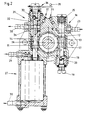
- the devices shown in Figs. 1 to 3 each have in a housing 10 on the Crankshaft 11 arranged helical gear 12 on opposite sides with counter wheels 13 and 14 in Intervention stands.
- the counter wheel 13 drives the Housing part 15 arranged lubricant pump 16 over the drive shaft 17, the drive shaft 17th the piston of the lubricant pump 16 at the same time Bearing pin for the counter wheel 13 forms.
- This piston 18a has an end sloping surface 18 as a lifting disk on against one in the housing 15 via a Adjustment screw 19 held lifting pin 20 abuts.
- At Rotation of the counter wheel 13 guides the drive shaft 17 oscillating up and down movements, whereby the (see Fig. 1) in the inlet port 21, 22 promoted Oil is pressed under pressure in the outlets 23, 24.
- the drive shaft 26 forms in a corresponding manner the opposite side a bearing journal for the Counter wheel 14 and serves to drive a fuel pump 27, the conveyor unit 28 via the inlet port 29 Sucks in fuel and pumps it into the outlet port 30.
- the two drive shafts for the lubricant pump 16 and the fuel pump 27 are parallel to each other aligned. This results in a compact dense design that is used in internal combustion engines for Hand-held tools are beneficial. Alternatively for this it would also be possible to drive the drive shaft 17th and 26 to be arranged in a V-shape.
- Fig. 2 Unit block through the crankshaft 11 that Helical gear 12 driven, which in the counter wheels 13, 14 engages.
- the drive shaft 17 serves as Bearing journal for the counter gear 13.
- the drive shaft 17 is part of a lubricant pump 16, which over the Inlet 21 the lubricant in the outlet port 23rd promotes.
- Corresponding same parts as the Lifting disc 18, the lifting pin 20 and the adjusting screw 19 and the spring 25 are the same Reference numerals as designated in Figure 1.
- On the opposite side serves the counter gear 14 and the Drive shaft 26 both for driving the fuel pump 27 and for driving the lubricant pump 31, the is arranged above the fuel pump 27.
- the Drive shaft 26 has one at its upper end frontal and serving as a lifting disc 32 Inclined surface against an adjustable lifting pin 33 is present.
- An actuating unit serves in the direction of the drive shaft 26 34, which has a manual operating lever 35 can be operated.
- the piston 36, the part of the Drive shaft 26, feeds through an inlet 37th lubricant entering the outlet 38 in after the State of the art for plunger pumps known Wise.
- the actuator 34 above the drive shafts 17 and 26 and across Longitudinal axis of the crankshaft 11 arranged.
- the adjustable actuator 34 for controlling the Pump delivery rate of the lubricant pump 16 below the Counter wheels 13 and 14 arranged while the Set screw 19 for the axial displacement of the previously described lifting pin 33 and thus to regulate the Delivery rate of the lubricant pump 31 is used.
- This too as an auxiliary unit block of an internal combustion engine, trained especially for two-stroke chainsaws Device is compact and uses Application of a few components through the Crankshaft rotation available during engine operation standing energy.
Description
- Fig. 1 bis 3
- im Schnitt quer zur Kurbelwellenachse jeweils unterschiedliche Ausführungen der erfindungsgemäßen Vorrichtung.
- Gehäuse
- 10
- Kurbelwelle
- 11
- Schraubenrad
- 12
- Gegenräder
- 13, 14
- Gehäuseteil
- 15
- Schmiermittelpumpe
- 16
- Antriebswelle
- 17
- Schrägfläche
- 18
- Einstellschraube
- 19
- Hubstift
- 20
- Einlaßstutzen
- 21, 22
- Auslässe
- 23, 24
- Feder
- 25
- Antriebswelle
- 26
- Kraftstoffpumpe
- 27
- Fördereinheit
- 28
- Einlaßstutzen
- 29
- Auslaßstutzen
- 30
- Schmiermittelpumpe
- 31
- Hubscheibe
- 32
- Hubstift
- 33
- Stelleinheit
- 34
- Betätigungshebel
- 35
- Kolben
- 36
- Einlaß
- 37
- Auslaß
- 38
- Fördereinheiten
- 161, 162
Claims (10)
- Vorrichtung mit Kraftstoffeinspritzung und Schmiermittelfördereinrichtung für Verbrennungsmotoren, vorzugsweise für von Hand geführte Werkzeuge, wie Kettensägen, mit einem auf einer Kurbelwelle (11) angeordneten oder indirekt durch die Kurbelwelle (11) angetriebenen Schraubenrad (12), das mit einem Gegenrad (13) zum Antrieb der Schmiermittelpumpe (16) in Eingriff steht, wobei ein Kolben (18a) der Schmiermittelpumpe (16) einen Lagerzapfen für das Gegenrad (13) bildet und eine stirnseitige Schrägfläche (18) aufweist, die gegen einen im Gehäuse einstellbar gehaltenen Hubstift (20) anliegt, worüber die Fördermenge der Schmiermittelpumpe (16) einstellbar ist,
dadurch gekennzeichnet,
daß das Schraubenrad (12) mit zwei Gegenrädern (13, 14) im Eingriff steht, von denen jedes mit einer Antriebswelle (17, 26) für jeweils eine Schmiermittel- (16, 31) und/oder eine Kraftstoffpumpe (27) verbunden ist. - Vorrichtung nach Anspruch 1,
dadurch gekennzeichnet,
daß die Antriebswellen (17, 26) für die Schmiermittel- (16, 31) und/oder Kraftstoffpumpe (27) parallel oder V-förmig zueinander ausgerichtet sind. - Vorrichtung nach Anspruch 1 oder 2,
dadurch gekennzeichnet,
daß einem der Gegenräder (13) beiderseits je eine Fördereinheit (161, 162) für Schmiermittel zugeordnet ist, wobei vorzugsweise beide Fördereinheiten (161, 162) von einer Hubscheibe (18) an einer der Fördereinheiten (162) antreibbar sind. - Vorrichtung nach Anspruch 3,
dadurch gekennzeichnet,
daß die Fördereinheiten (161, 162) für Schmiermittel verschieden große wirksame Kolbenflächen aufweisen. - Vorrichtung nach einem der Ansprüche 1, 2 oder 4,
dadurch gekennzeichnet,
daß einem der Gegenräder (14) beiderseits jeweils eine Fördereinheit zugeordnet ist, wovon eine dieser Fördereinheiten als kontinuierlich arbeitende Kraftstoffpumpe (27) und die andere Fördereinheit eine in der Fördermenge verstellbare Schmiermittelpumpe (31) ist. - Vorrichtung nach Anspruch 5,
dadurch gekennzeichnet,
daß dem anderen Gegenrad (13) eine fest einstellbare Schmiermittelpumpe (16) zugeordnet ist. - Vorrichtung nach Anspruch 5 oder 6,
dadurch gekennzeichnet,
daß die Stelleinheit (34) für die regelbare Schmiermittelpumpe (31) in einer Achse oberhalb der Achsen der Gegenräder (13, 14) angeordnet ist, vorzugsweise quer zur Kurbelwellenachse. - Vorrichtung nach einem der Ansprüche 5 bis 7,
dadurch gekennzeichnet,
daß das die Kraftstoffpumpe (27) und/oder die Schmiermittelfördereinrichtung (16, 31) treibende Gegenrad (13, 14) axial beidseitig im Gehäuseblock (10, 15) geführt ist. - Vorrichtung nach einem der Ansprüche 5 bis 8,
dadurch gekennzeichnet,
daß der Kolben (36) oder die Hubscheibe (32) der regelbaren Schmiermittelpumpe mit dem zugeordneten Gegenrad (14) drehfest, aber schubbeweglich in Eingriff steht. - Vorrichtung nach einem der Ansprüche 1 bis 9,
dadurch gekennzeichnet,
daß alle Schmiermittelpumpen (16, 31) als regelbare Fördereinheiten ausgebildet sind.
Applications Claiming Priority (3)
| Application Number | Priority Date | Filing Date | Title |
|---|---|---|---|
| DE19529368 | 1995-08-10 | ||
| DE19529368A DE19529368C1 (de) | 1995-08-10 | 1995-08-10 | Vorrichtung mit Kraftstoffeinspritzung und Schmiermittelfördereinrichtung für Verbrennungsmotoren |
| PCT/EP1996/003424 WO1997006359A1 (de) | 1995-08-10 | 1996-08-02 | Vorrichtung mit kraftstoffeinspritzung und schmiermittelfördereinrichtung für verbrennungsmotoren |
Publications (2)
| Publication Number | Publication Date |
|---|---|
| EP0786047A1 EP0786047A1 (de) | 1997-07-30 |
| EP0786047B1 true EP0786047B1 (de) | 2000-06-07 |
Family
ID=7769128
Family Applications (1)
| Application Number | Title | Priority Date | Filing Date |
|---|---|---|---|
| EP96927669A Expired - Lifetime EP0786047B1 (de) | 1995-08-10 | 1996-08-02 | Vorrichtung mit kraftstoffeinspritzung und schmiermittelfördereinrichtung für verbrennungsmotoren |
Country Status (5)
| Country | Link |
|---|---|
| US (1) | US5787854A (de) |
| EP (1) | EP0786047B1 (de) |
| AU (1) | AU6741596A (de) |
| DE (2) | DE19529368C1 (de) |
| WO (1) | WO1997006359A1 (de) |
Families Citing this family (9)
| Publication number | Priority date | Publication date | Assignee | Title |
|---|---|---|---|---|
| DE19808887A1 (de) * | 1998-03-03 | 1999-09-09 | Dolmar Gmbh | Handarbeitsgerät mit 2-Takt-Brennkraftmaschine und Getrenntschmierung sowie kombinierte Förder/Dosierpumpe für ein solches Handarbeitsgerät |
| US5964198A (en) * | 1998-04-29 | 1999-10-12 | Industrial Technology Research Institute | Lubrication system of internal combustion engine |
| DE20006638U1 (de) | 2000-04-11 | 2001-08-30 | Dolmar Gmbh | Medienpumpe |
| US6644250B1 (en) * | 2000-09-27 | 2003-11-11 | Bombardier Motor Corporation Of America | Engine oiling system and an oil system distribution manifold, and method of use |
| DE102004036555A1 (de) * | 2003-08-01 | 2005-03-03 | Andreas Stihl Ag & Co. Kg | Pumpsystem zur Förderung von Schmieröl |
| US7299780B1 (en) * | 2004-06-05 | 2007-11-27 | Thompson Brian M | Dual high-pressure lube-oil pumps for diesel fuel injection |
| DE102010016357A1 (de) | 2010-04-07 | 2011-10-13 | A. T. Süd GmbH | Verbrennungskraftmaschine mit Kraftstoffpumpe |
| SE539242C2 (sv) * | 2013-12-05 | 2017-05-30 | Scania Cv Ab | Drivarrangemang för en bränslepump |
| US9862116B2 (en) | 2014-11-20 | 2018-01-09 | Black & Decker Inc. | Dual speed gearboxes, transmissions, and apparatuses incorporating the same |
Family Cites Families (18)
| Publication number | Priority date | Publication date | Assignee | Title |
|---|---|---|---|---|
| DD41648A (de) * | ||||
| JPS4937260A (de) * | 1972-08-14 | 1974-04-06 | ||
| DK169775A (da) * | 1974-04-30 | 1975-10-31 | A Batscheider | Fremgangsmade til naturlig vitaminisering af korn |
| US3938622A (en) * | 1974-10-17 | 1976-02-17 | Outboard Marine Corporation | Chain saw oil pump with overload protection |
| US4411602A (en) * | 1979-02-12 | 1983-10-25 | Ray Earl L | Fuel injection apparatus for internal combustion engines |
| US4539949A (en) * | 1981-10-08 | 1985-09-10 | Outboard Marine Corporation | Combined fluid pressure actuated fuel and oil pump |
| US4383504A (en) * | 1981-11-23 | 1983-05-17 | Outboard Marine Corporation | Marine propulsion device with mechanical fuel pressure operated device for supplying a fuel/oil mixture |
| JPS5937260A (ja) * | 1982-08-24 | 1984-02-29 | Yanmar Diesel Engine Co Ltd | 内燃機関用燃料噴射装置 |
| JPS6030427A (ja) * | 1983-07-29 | 1985-02-16 | Iseki & Co Ltd | エンジンの附隨機構部連動装置 |
| US4551076A (en) * | 1983-10-07 | 1985-11-05 | Outboard Marine Corporation | Fluid driven pump with one-way valve in fluid inlet |
| DE3341658C2 (de) * | 1983-11-18 | 1986-07-10 | GerroKaiser Dosenwerk GmbH & Co KG, 4350 Recklinghausen | Vorrichtung zum Schmieren einer Kette |
| SE463221B (sv) * | 1985-08-21 | 1990-10-22 | Tetra Pak Ab | Doseringspump |
| SE458265C (sv) * | 1985-11-11 | 1991-03-26 | Electrolux Ab | Anordning med oljepump |
| JPS62253927A (ja) * | 1986-04-28 | 1987-11-05 | Sanshin Ind Co Ltd | 燃料噴射機関 |
| DE3735711C2 (de) * | 1987-10-22 | 1995-03-16 | Stihl Maschf Andreas | Zweitaktmotor mit pneumatisch betätigter Einspritzpumpe zum Antrieb eines Arbeitsgerätes |
| DE3818802C2 (de) * | 1988-06-03 | 1994-05-26 | Baier & Koeppel | Schmiermittelpumpe mit einer Hubbetätigung eines Förderkolbens und mit einer einstellbaren Dosierung |
| US5315971A (en) * | 1991-07-15 | 1994-05-31 | Yamaha Hatsudoki Kabushiki Kaisha | Lubricating oil supplying device for engine |
| DE9203378U1 (de) * | 1992-03-13 | 1992-04-23 | Dolmar Gmbh, 2000 Hamburg, De |
-
1995
- 1995-08-10 DE DE19529368A patent/DE19529368C1/de not_active Expired - Fee Related
-
1996
- 1996-08-02 WO PCT/EP1996/003424 patent/WO1997006359A1/de active IP Right Grant
- 1996-08-02 DE DE59605397T patent/DE59605397D1/de not_active Expired - Fee Related
- 1996-08-02 AU AU67415/96A patent/AU6741596A/en not_active Abandoned
- 1996-08-02 EP EP96927669A patent/EP0786047B1/de not_active Expired - Lifetime
- 1996-08-02 US US08/817,240 patent/US5787854A/en not_active Expired - Fee Related
Also Published As
| Publication number | Publication date |
|---|---|
| US5787854A (en) | 1998-08-04 |
| EP0786047A1 (de) | 1997-07-30 |
| DE19529368C1 (de) | 1996-10-31 |
| AU6741596A (en) | 1997-03-05 |
| WO1997006359A1 (de) | 1997-02-20 |
| DE59605397D1 (de) | 2000-07-13 |
Similar Documents
| Publication | Publication Date | Title |
|---|---|---|
| EP0786047B1 (de) | Vorrichtung mit kraftstoffeinspritzung und schmiermittelfördereinrichtung für verbrennungsmotoren | |
| EP1859170B1 (de) | Drehkolbenmaschine | |
| CH684020A5 (de) | Trockenlaufender Hubkolben-Kompressor. | |
| DE3447091A1 (de) | Oelpumpe | |
| DE4216703A1 (de) | Fahrzeuggetriebe | |
| DE102005030725A1 (de) | Kompressoreinheit | |
| EP0405118A1 (de) | Als Rotorpumpe ausgebildete Kraftstofförderpumpe | |
| EP3077135B1 (de) | Oszillierend antreibbare werkzeugmaschine | |
| DE3307735A1 (de) | Schmieroel-zufuehrvorrichtung fuer eine kraftstoffeinspritzpumpe | |
| DE560073C (de) | Brennstoffpumpe | |
| DE10325310B4 (de) | Kraftstoffeinspritzpumpe | |
| EP2557334A1 (de) | Schaltbare Riemenscheibe | |
| EP1111234B1 (de) | Kraftstoffpumpe | |
| DE102014102131A1 (de) | Oszillierend antreibbare Werkzeugmaschine | |
| DE1453173A1 (de) | OElpumpe | |
| DE2650908A1 (de) | Innenzahnradmaschine (pumpe oder motor) | |
| DE3126002A1 (de) | Kraftstoffeinspritzvorrichtung | |
| DE695664C (de) | Entlueftungseinrichtung fuer den Saugraum von Einspritzpumpen | |
| DE10220838C1 (de) | Brennkraftmaschine | |
| DE19519154A1 (de) | Kettensäge | |
| DE2532480A1 (de) | Brennstoffeinspritzpumpenvorrichtung fuer brennkraftmaschinen | |
| DE19834599C2 (de) | Flüssigkeits-Fördersystem | |
| CH406030A (de) | Von Hand geführte Werkzeugmaschine zur Steinbearbeitung | |
| DE1292004B (de) | Transportables, motorisch angetriebenes Fluessigkeitshochdruckkolbenpumpenaggregat | |
| DE391799C (de) | Druckfluessigkeitsantrieb |
Legal Events
| Date | Code | Title | Description |
|---|---|---|---|
| PUAI | Public reference made under article 153(3) epc to a published international application that has entered the european phase |
Free format text: ORIGINAL CODE: 0009012 |
|
| 17P | Request for examination filed |
Effective date: 19970409 |
|
| AK | Designated contracting states |
Kind code of ref document: A1 Designated state(s): DE FR IT SE |
|
| GRAG | Despatch of communication of intention to grant |
Free format text: ORIGINAL CODE: EPIDOS AGRA |
|
| GRAG | Despatch of communication of intention to grant |
Free format text: ORIGINAL CODE: EPIDOS AGRA |
|
| GRAH | Despatch of communication of intention to grant a patent |
Free format text: ORIGINAL CODE: EPIDOS IGRA |
|
| 17Q | First examination report despatched |
Effective date: 19990922 |
|
| GRAH | Despatch of communication of intention to grant a patent |
Free format text: ORIGINAL CODE: EPIDOS IGRA |
|
| GRAA | (expected) grant |
Free format text: ORIGINAL CODE: 0009210 |
|
| ITF | It: translation for a ep patent filed |
Owner name: ST. TECN. INGG. SIMONI - DE BLASIO |
|
| AK | Designated contracting states |
Kind code of ref document: B1 Designated state(s): DE FR IT SE |
|
| REF | Corresponds to: |
Ref document number: 59605397 Country of ref document: DE Date of ref document: 20000713 |
|
| PGFP | Annual fee paid to national office [announced via postgrant information from national office to epo] |
Ref country code: FR Payment date: 20000817 Year of fee payment: 5 |
|
| ET | Fr: translation filed | ||
| PGFP | Annual fee paid to national office [announced via postgrant information from national office to epo] |
Ref country code: SE Payment date: 20000825 Year of fee payment: 5 |
|
| PGFP | Annual fee paid to national office [announced via postgrant information from national office to epo] |
Ref country code: DE Payment date: 20001020 Year of fee payment: 5 |
|
| PLBE | No opposition filed within time limit |
Free format text: ORIGINAL CODE: 0009261 |
|
| STAA | Information on the status of an ep patent application or granted ep patent |
Free format text: STATUS: NO OPPOSITION FILED WITHIN TIME LIMIT |
|
| 26N | No opposition filed | ||
| PG25 | Lapsed in a contracting state [announced via postgrant information from national office to epo] |
Ref country code: SE Free format text: LAPSE BECAUSE OF NON-PAYMENT OF DUE FEES Effective date: 20010803 |
|
| EUG | Se: european patent has lapsed |
Ref document number: 96927669.0 |
|
| PG25 | Lapsed in a contracting state [announced via postgrant information from national office to epo] |
Ref country code: FR Free format text: LAPSE BECAUSE OF NON-PAYMENT OF DUE FEES Effective date: 20020430 |
|
| PG25 | Lapsed in a contracting state [announced via postgrant information from national office to epo] |
Ref country code: DE Free format text: LAPSE BECAUSE OF NON-PAYMENT OF DUE FEES Effective date: 20020501 |
|
| REG | Reference to a national code |
Ref country code: FR Ref legal event code: ST |
|
| PG25 | Lapsed in a contracting state [announced via postgrant information from national office to epo] |
Ref country code: IT Free format text: LAPSE BECAUSE OF NON-PAYMENT OF DUE FEES Effective date: 20050802 |