EP0785687B1 - Picture image distributing apparatus provided within passenger moving vehicle - Google Patents
Picture image distributing apparatus provided within passenger moving vehicle Download PDFInfo
- Publication number
- EP0785687B1 EP0785687B1 EP97103840A EP97103840A EP0785687B1 EP 0785687 B1 EP0785687 B1 EP 0785687B1 EP 97103840 A EP97103840 A EP 97103840A EP 97103840 A EP97103840 A EP 97103840A EP 0785687 B1 EP0785687 B1 EP 0785687B1
- Authority
- EP
- European Patent Office
- Prior art keywords
- optical
- picture image
- signals
- transmission path
- electric
- Prior art date
- Legal status (The legal status is an assumption and is not a legal conclusion. Google has not performed a legal analysis and makes no representation as to the accuracy of the status listed.)
- Expired - Lifetime
Links
Images


Classifications
-
- H—ELECTRICITY
- H04—ELECTRIC COMMUNICATION TECHNIQUE
- H04N—PICTORIAL COMMUNICATION, e.g. TELEVISION
- H04N7/00—Television systems
- H04N7/16—Analogue secrecy systems; Analogue subscription systems
-
- H—ELECTRICITY
- H04—ELECTRIC COMMUNICATION TECHNIQUE
- H04N—PICTORIAL COMMUNICATION, e.g. TELEVISION
- H04N7/00—Television systems
- H04N7/22—Adaptations for optical transmission
Definitions
- the present invention generally relates to a picture image distributing apparatus provided within a passenger moving vehicle for distributing to the respective passenger seats the multichannel picture image signals within the passenger moving vehicle.
- the conventional picture image distributing apparatus provided within a passenger moving vehicle is one using the same coaxial cables as in, for example, CATV.
- the distributing operation of the signals is effected by the taking out operation of the signals where necessary by a tapping system from the coaxial cable.
- a network construction of distributing optical signals with the use of optical fibers generally uses topology of a star type using an optical branching unit of such equal distribution as shown in Fig. 7 (A), of a double star type or of a multistage star type as in Fig. 7 (B). This is because the loss as the whole network which becomes a problem in the optical signal distribution can be reduced as much as possible as the optical branching unit of the equal distribution is the least in the excessive loss. Therefore, the number of all the distributions can be made as many as possible.
- electromagnetic interferences are easy to, not only, receive from the electromagnetic environment inferior within the passenger moving vehicle, but also, to generate the electromagnetic interferences with respect to the other appliances, with a problem that the influences upon the signals by differences and variations in the earth electric potential are unavoidable.
- the optical fibers In order to avoid such electromagnetic task, it is effective to use the optical fibers as a transmission path.
- the number of the core wires of the optical fibers to be laid in the longitudinal direction becomes more within the passenger moving vehicle of such narrow construction as airplane or train, and especially becomes more near the head end portion.
- the passenger moving vehicle of such a narrow construction as the airplane and the train is narrow therein in the conduit lines for the transmission path use or in the space for them, with a large problem that the optical fibers of many cores are laid. Weight increases, and wirings become complicated. There is a problem that it takes more time to detect the trouble locations at the breaks of the optical fibers.
- optical fibers are required to be connected with the optical connectors so as to be disengaged halfway from on the transmission path for the maintenance, the number of the optical connections become extremely numerous, and the space for them become larger.
- the optical fibers are connected again after the disconnection thereof, with a problem that the discrimination among the optical fibers is hard to effect.
- the invention defined in claim 1 is directed to a picture image distributing apparatus provided within a passenger moving vehicle comprising a head end portion related to picture image signals and outputting electric signals multiplexed in frequency, an electric optical converting portion for converting into optical signals the electric signals of the head end portion, a first optical amplifying portion for optically amplifying the optical signals from the electric optical converting portion, a branching portion for branching in two the optical output of the first optical amplifying portion, two lines of optical fiber transmission paths, a first transmission path and a second transmission path, connected in series with a plurality of optical branching units of fusion type having two inputs and two outputs of non-equal distribution for halfway branching one portion of optical power of the optical signals, a second optical amplifying portion for optically amplifying the optical output from the final point of the first transmission path to input into the final point of the second transmission path, a third optical amplifying portion for optically amplifying the output from the final point of the second transmission path to input into the final point of the first transmission path
- the head end portion is related to picture image signals and outputs electric signals multiplexed in frequency: the electric optical converting portion optically amplifies the electric signals from the head end portion: the first optical amplifying portion optically amplifies the optical signals from the electric optical converting portion: the branching portion branches in two the optical output from the optical amplifying portion: the first and second optical fiber transmission paths are respectively connected with two branching portions to transmit the optical signals from the two branching portions, and connected in series with a plurality of optical branching units of fusion type having two inputs and two outputs of non-equal distribution for halfway branching one portion of the optical power of the optical signals: the second optical amplifying portion optically amplifies the optical outputs from the final point of the first optical transmission path to input into the final point of the second transmission path: the third optical amplifying portion optically amplifies the outputs from the final point of the second transmission path to input into the final point of the first transmission path: the plurality of optical electric converting portions receive two optical signals from two outputs of
- Another embodiment of the invention is defined by the features of claim 2.
- the picture image signals of a multichannel can be distributed to the respective passenger seats efficiently within the passenger moving vehicle of such narrow construction as in the airplane and the train. Therefore, the less number of the optical connectors for maintenance use will do, the type of the branching units can be reduced, the wiring amount can be also reduced, thus resulting in lighter amount. Further, the signal distribution can be effected in much more amount. As the number of the optical connectors and the type of the branching units can be reduced, thus resulting in lower cost. Higher reliability, easier maintenance and repairs are provided.
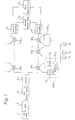
- Fig. 1 is a block diagram of a picture image distributing apparatus provided within a passenger moving vehicle in an example 1.
- the picture image distributing apparatus provided within the passenger moving vehicle is provided with a head end portion 1, an electric optical converting portion (hereinafter referred to as "E/O portion") 2, an optical amplifying portion 3, an optical taps 4 1 through 4 n as optical branching units, optical electric converting portions (hereinafter referred to as "O/E portion) 5 1 through 5 n , 5 o1 through 5 om , an optical branching unit 6, a passenger seat picture image terminals 7 1 through 7 p .
- E/O portion electric optical converting portion
- the passenger seat picture image receiving terminals 7 1 through 7 p are respectively connected even to the respective O/E portions 5 2 through 5 n , 5 o1 through 5 om except for the O/E portion 5 1 although the drawing is omitted.
- Each of the passenger seat picture image receiving terminals 7 1 is provided with a selecting channel operation portion for passenger 71 1 as a man-machine interface, a tuning portion 71 2 for tuning selectively the desired channel with the output electric signals of O/E portion 5 1 by controlling of the selecting channel operation portion for passenger 71 1 , a demodulation portion 71 3 for demodulating the signals of channel selected in tuning, and a picture image displaying portion 71 4 for displaying the demodulated picture image signals.
- the head end portion 1 relates to the picture image signals so as to output electric signals multiplexed in frequency.
- the E/O portion 2 converts into optical signals the electric signals outputted from the head end portion 1.
- the optical amplifying portion 3 optically amplifies the optical signals outputted from the E/O portion 2.
- the optical taps 4 1 through 4 n branches the light into the non-equal distribution.
- the O/E portions 5 1 through 5 n , 5 o1 through 5 om receive the optical signals from the optical taps 4 1 through 4 n or the optical branching unit 6 so as to convert them into electric signals.
- the optical branching unit 6 branches the light into the equal distribution.
- the passenger seat picture image receiving terminals 7 1 through 7 p receive the electric signals from the O/E portions 5 1 through 5 n , 5 o1 through 5 om .
- An optical fiber transmission path is composed with the optical fibers being connected among the optical amplifying portion 3 and the optical taps 4 1 through 4 n , the optical branching unit 6 and the O/E portions 5 1 through 5 n , 5 o1 through 5 om .
- the electric signals from the head end portion 1 are converted into the optical signals by the E/O portion 2, are optically amplified by the optical amplifying portion 3, and outputted into the optical fiber transmission path.
- the optical signals branched by the optical taps 4 1 through 4 n are received respectively by the O/E portions 5 1 through 5 n , and are converted into electric signals, namely, signals equivalent to the output signals from the head end portion 1.
- the larger signal of the output optical signals from the optical tap 4 n is equally distributed by the optical distributing unit 6, is received respectively by the O/E portions 5 o1 through 5 om , and is converted into the electric signals.
- the passenger seat picture image receiving terminals 7 1 through 7 p connected to the respective O/E portions 5 1 through 5 n , 5 o1 through 5 om receive the electric signals from the O/E portions 5 1 through 5 n , 5 o1 through 5 om so as to reproduce the picture images.
- a passenger operates the selecting channel operation portion 71 1 to select the picture image program of channel to be received, by which operation the selecting channel operation portion 71 1 is controlled by the inputted signals the tuning portion 71 2 so as to selectively tune the desired channel from the output electric signals of the O/E portion 5 1 .
- the channel signal selected in tuning by the tuning portion 71 2 is demodulated with the demodulating portion 71 3 , and the demodulated signals are displayed in reproduction with the picture displaying portion 71 4 so that a passenger can see the picture image program of selected channel.
- the number of the optical taps 4 1 through 4 n and the branching number of the optical branching units 6 are determined depending upon the level difference between the transmission and reception.
- the number of the passenger seat picture image receiving terminals 7 1 through 7 p to be connected with the respective O/E portions 5 1 through 5 n , 5 o1 through 5 om depends upon the actual seat arrangement and the electromagnetic environment and is determined individually.
- the electric signals, which are related to the picture images and multiplexed in frequency, to be outputted from the head end portion 1 may be one FM-FDM (Frequency Division Multiplexing) signal with, for example, multichannel FM picture image signals being multiplexed in frequency or may be one QAM-FDM signal having the multichannel signals multiplexed in frequency with the respective digital picture image signals being modulated by the QAM system.
- FM-FDM Frequency Division Multiplexing
- the tuning and demodulating operations of the channel may be effected by the O/E portions 5 1 through 5 n , 5 o1 through 5 om so as to transmit in a base band signal format the desired picture image signals to the respective passenger seat picture image receiving terminals 7 1 through 7 p from the O/E portions 5 1 through 5 n , 5 o1 through 5 om .
- the tuning and QAM modulating operations of the channel may be effected by the O/E portions 5 1 through 5 n , 5 o1 through 5 om so as to transmit in the digital signal format the desired picture image signals to the respective passenger seat picture image receiving terminals 7 1 through 7 p from the O/E portions 5 1 through 5 n , 5 o1 through 5 om .
- the tuning and QAM demodulating of the channel, and the decode of the digital picture signals may be effected by the O/E portions 5 1 through 5 n , 5 o1 through 5 om so as to transmit in the base band signal format the desired picture image signals to the respective passenger seat picture image receiving terminals 7 1 through 7 p from the O/E portions 5 1 through 5 n , 5 o1 through 5 om .
- a signal processing function for reproducing the base band picture image signals from the electric signals of the FDM format is roughly divided into the tuning and demodulating operations.
- the modulating system is QAM, a processing function of the decode is added to it.
- the signal format between the O/E portions 5 1 through 5 n , 5 o1 , through 5 om and the passenger seat picture image receiving terminals 7 1 through 7 p is determined by the way of the charging operation.
- the charging way of the processing function is changed by the diversion of the market goods to a module to be used for the respective portions or the new integration of the functions, and is influenced even by the cost, size, suitable connection form.
- the space for providing the passenger seat picture image receiving terminal 7 1 to 7p within a customer's cabin is limited, it is desirable to give lots of functions as much as possible to the O/E portions 5 1 to 5 n , 5 01 , to 5 0m .
- the O/E portions 5 1 to 5 n , 5 01 , to 5 0m it is preferable for the O/E portions 5 1 to 5 n , 5 01 , to 5 0m to convert the optical signals into electric signals having proper levels to supply the signals onto the passenger seat picture image receiving terminals 7 1 to 7 p in the form of bus.
- bus form On the employment of bus form, it may be transmitted the optical signals of themselves to the passenger seat picture image receiving terminals through the O/E portions 5 1 to 5 n , 5 01 , to 5 0m , or to transmit the frequency multiplexed signals converting in frequency to transmitting frequencies allocated respectively to the passenger seat picture image receiving terminals 7 1 to 7p.
- each of the passenger seat picture image receiving terminals 7 1 to 7p is enough for receiving only the signal of frequency allocated to itself. In general, it may be shortened the transmitting path adapted as a form of bus.
- connection form between the O/E portions 5 1 through 5 n , 5 o1 through 5 om and the passenger seat picture image receiving terminals 7 1 through 7 p is a bus type in the above described example 1, the other type such as a star type may be used. Especially if the signal format in the portion is a base band form, a star form is suitable.
- Fig. 2 is an illustrating view in a concrete example of an optical branching operation of the optical fiber transmission path
- optical taps 4 1 through 4 16 are 20 dB taps
- the optical taps 4 17 through 4 24 are 10 dB taps.
- the optical branching unit 6 is four branching units. Assume that the loss of the optical taps 4 1 through 4 16 which are the 20 dB taps is 22 dB and 0.5 dB including the excess loss, the loss of the optical taps 4 17 through 4 24 which are 10 dB taps are 11.5 dB and 1 dB including the excessive loss, the loss of per output of the optical branching unit 6 which are 4 branching units is 7 dB including the excess loss .
- the level difference between the transmission and the reception being 36 dB.
- An optical connector is provided respectively among the respective optical taps 4 1 through 4 24 , between the optical taps 4 24 and the optical branching unit 6, between the optical tap 4 1 and the optical amplifying portion 3.
- the loss thereof is 0.2 dB per one optical connector, and the number of the branches is determined as shown in Fig. 2. Namely, in this example, 28 branches are possible.
- four passenger seat picture image receiving terminals 7 1 through 7 4 can be connected respectively with twenty eight O/E portions 5 1 through 5 28 , and one hundred twelve passenger seat picture receiving terminals can be connected as a whole.
- the number of branches can be increased if more types of optical taps 4 1 through 4 n and optical branching units 6 are used in accordance with the optical signal levels of the respective portions. Therefore, the total number of the passenger seat picture image receiving terminals can be increased.
- the branching ratios among the optical taps 4 1 to 4 n are proper at the respective positions, the total sum of branchings becomes maximum to be effective, but it needs to prepare many kinds of the optical taps 4 1 to 4 n corresponding to the kinds of branching ratios, so that the number of kinds becomes slightly large, and it is necessary to keep always the whole kinds of branchings for exchanging in maintenance at large cost.
- the number of kinds of branching is limited in practical use without any reduction of the property of itself, and it is rendered to present a merit of cost reduction and easy maintenance.
- the apparatus it can be reduced the initial cost for the installation in general.
- the margin in the representative points there are 13.8 dB in the input end of the O/E portion 5 1 , 6.6 dB in the input end of the O/E portion 5 9 , 0.3 dB in the input end of the O/E portion 5 16 , 9. 9 dB in the input end of the O/E portion 5 17 , 0.1 dB in the input end of the O/E portion 5 24 , 3. 2 dB in the input end of the O/E portions 5 25 through 5 28 .
- the margin is considerably different in location in this manner, it is possible to further increase the number of the whole branches if the optical signal is branched after branching at the respective optical taps 4, through 4 24 . The example in this case is shown.
- Fig. 3 is an illustrating view in the other concrete example of the optical branches of the optical fiber transmission path.
- optical branching units 6 1 through 6 10 composed of four branching units and optical branching units 6 21 through 6 27 composed of two branching units are added.
- the loss per output of the optical branching units 6 1 through 6 10 composed of four branching units is 7 dB including the excessive loss
- the loss per output of the optical branching units 6 21 through 6 27 composed of two branching units is 3.5 dB including the excessive loss
- the other conditions are the same as in the example shown in Fig. 2.
- Optical branching units 6 1 through 6 10 are inserted into the rear stage side of the optical taps 4 1 through 4 8 , 4 17 , 4 18 , and the optical branching units 6 21 through 6 27 are inserted into the rear stage side of the optical taps 4 9 through 4 12 , 4 19 through 4 21 , and sixty five branches can be provided.
- four passenger seat picture image receiving terminals 7 1 through 7 4 can be connected respectively with sixty five O/E portions 5 1 through 5 65 , and two hundred sixty passenger seat picture image receiving terminals can be connected as a whole.
- such construction may be provided as described hereinabove if possible, in accordance with the actual condition of the optical fiber laying operation.
- optical power is branched at the portion having spare power for branching.
- Fig. 4 is a block diagram of a picture image distributing apparatus provided within a passenger moving vehicle in the example 2. As compared with the example 1 shown in Fig. 1, Fig. 4 is different from the construction wherein the optical amplifying portion 3 is provided halfway on the optical fiber transmission path. The passenger seat picture image receiving terminals 7 1 through 7 P are omitted in the drawing.
- Such construction is adopted when the output of the E/O portion 2 is larger. Especially, the construction is suitable when the output level is too large to place the optical amplifying portion 3 immediately after the E/O portion 2.
- the inserting position of the optical amplifying portion 3 is determined in the optimum location by the NF characteristics and the gains of the optical amplifying portion 3.
- the optical amplifying portion 3 is an optical fiber amplifier.
- One way is to have an excitation optical power supply in the optical amplifying portion 3, and the other method is to transmit the excitation light till the optical amplifying portion 3 through the transmission path the same in the optical signal from the side of the head end portion 1.
- the damping operation of the excitation light can be restrained to minimum if the wavelength dependency where the optical signal is branched, but the excitation light is not branched is adopted in the optical taps 4 1 through 4 n .
- optical taps having the property depending on the wavelength By employing the optical taps having the property depending on the wavelength, it can be presented advantages such that the optical power for exciting from the light source for optical pumping is used effectively, and the light source for optical pumping is small enough for the output power.
- the optical power is amplified with providing in halfway of the optical fiber transmission path the optical amplifying portion 3 to amplify the optical power, it is a merit of increasing the number of branching in addition to that, if the optical power is amplified to a proper level, the same type of optical taps as used in the optical fiber transmission path before the optical amplifying portion can be employed even on the proceeding optical fiber transmission path after the optical amplifying portion 3 so that the number of kinds of optical taps can be reduced.
- Fig. 5 is a block diagram of a picture image distributing apparatus provided within a passenger moving vehicle in the example 3.
- Fig. 5 is different from the construction where the optical amplifying portion 3 2 is added as compared with the example 1 shown in Fig. 1.
- the passenger seat picture image receiving terminals 7 1 through 7 p are omitted in the drawing.
- the optical amplifier portion 3 2 achieves as a function of a repeater. As the optical amplifying portion 3 2 is not noiseless, the number of the repetition stages cannot be increased without limit.
- Two exciting methods are provided when the optical amplifying portions 3 1 , 3 2 are the optical fiber amplifiers in such construction.
- One is a method of having an exciting light source, and the other is a method of transmitting the exciting light so far as the optical amplifying portions 3 1 , 3 2 through the transmission path the same as in the optical signal from the side of the head end portion 1.
- the exciting light source is provided on the side of the head end portion 1, the maintenance has an advantage of becoming easier in operation. If a wavelength dependency where the optical signal is branched, but the exciting light is not branched is adopted in the optical taps 4 1 through 4 n , the damping operation of the excitation light can be restrained to minimum.
- the third example is a kind of combination of the previous two examples so that it has advantages for increasing the number of branching and for supplying the shortage of the optical output power of E/O portion 2 when it is small.
- the light source for optical pumping which does not contribute to the optical amplifying within the optical amplifying portion 3 1 among the whole light source for optical pumping of the optical amplifying portion 3 1 , is transmitted to the optical amplifying portion 3 2 through the optical fiber transmission path, it can be used effectively as the optical power of the light source for optical pumping. Especially, it is more effective to employ the above-mentioned ones depending upon the property of wavelength to the optical taps 4 1 to 4 n .
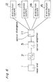
- Fig. 6 is a block diagram of a picture image distributing apparatus provided within a passenger moving vehicle in the example 4.
- the example is adapted to operate in parallel a picture image distributing apparatus provided within a passenger moving vehicle of the above described examples 1 through 3.
- the output of the optical amplifying portion 3 is branched by the optical branching unit 11 composed of four branching units so as to feed them to the distributing systems 12 through 15.
- Each of the distributing systems 12 through 15 is shown in Fig. 2 among the distributing system including the optical fiber transmission path through the passenger seat picture receiving terminals 7 1 through 7 P in the picture image distributing apparatus provided within the passenger moving vehicle in the above described example 1.
- Such construction assumes a passenger plane having the number of much more passenger seats in a lateral direction and a plurality of optical fibers are laid in parallel for each of the respective seat groups in the longitudinal direction so as to set four systems composed of the distributing systems 12 through 15 in parallel.
- the optical fibers and the electric cables for distribution use can be provided without the laying operation in the lateral direction as much as possible so that the fibers and the electric cables for the distributing use do not stride over the aisles.
- the output is branched at the rear stage of the optical amplifying portion 3, and may be branched anywhere on the rear stage side from the head potion 1.
- the reliability increases as the branching point is closer to the head end portion 1, the cost increases correspondingly, so that the balance thereof has only to be effected.
- each of the distributing systems 12 through 15 is shown in Fig. 2 among the distributing systems including from the optical fiber transmission path to the passenger seat picture image receiving terminals 7 1 through 7 p in the picture image distributing apparatus provided within the passenger moving vehicle in the above described example 1, each of the distributing systems 12 through 15 may be shown in Fig.
- the serial arrangement in the fourth example has an advantage of providing an arrangement without crossing over the passages, which is useful especially in the case of installing the transmission within the wall. Also, when it can be obtained enough for the optical output from the output of optical amplifying portion, it is branched after the optical amplifying portion and designed in serial arrangement to decrease the number of kinds of the optical taps in addition to that the number of the whole branchings increases, which are advantages for this example.
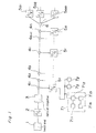
- Fig. 7 shows the construction of a picture image distributing apparatus provided within a passenger moving vehicle in accordance with the first embodiment, wherein the same components to those of the previously described examples are designated with the same reference numbers to the previous ones.
- the optical output from the first optical amplifying portion 3 1 is branched in two within the branching unit 8 1 to output to the two optical fiber transmission paths.
- the first optical fiber transmission path there are a plurality of optical branch units of fusion type having two inputs and two outputs of non-equal distribution 40 1 to 40 n-1 , 40 n connected with each other in series
- the second optical fiber transmission path there are a plurality of optical branch units for fusion type having two inputs and two outputs of non-equal distribution 40 n+1 to 40 k connected with each other in series.
- the two optical signals from two outputs of the optical branching units 40 1 are received within the optical electric converting portion 51 1 and 51 2 among the respective optical electric converting portions 500 1 to convert into electric signals.
- the diversity receiving portion 51 3 is outputted upon selecting the large one of outputs from the optical electric converting portions 51 1 and 51 2 .
- the diversity receiving portion 51 3 there are connected with the same passenger seat picture image receiving terminals 7 1 to 7 p to those of the previous examples, while the other optical branch units of fusion types are connected with the apparatus having the same construction to those of the previous examples. For instance, it will be explained hereinafter the flow of signals relating to the optical branch units 40 1 , which is also applied in the same manner to ones of the other parts.
- the signals from the head end portion 1 is branched in two by the branch unit 8 1 , one output of which being outputted into the first optical fiber transmission path.
- the portion of the optical signals from the first optical fiber transmission path is taken out by the optical branch unit of fusion type 40 1 to input into the optical electric converting portion 51 2 among the optical electric converting portions 500 1 .
- One of the branch output from the branch unit 8 1 is outputted into the second optical fiber transmission path.
- the portion of the optical signals from the second optical fiber transmission path is taken out by the optical branch unit of fusion type 40 1 to input into the electric optical converting portion 51 1 among the electric optical converting portions 500 1 .
- the diversity receiving portion 51 3 among the optical electric converting portion 500 1 selects the large one of outputs from the optical electric converting portions 51 1 and 51 2 to output into the passenger seat picture image receiving terminals 7 1 to 7p.
- An optical circulator can be employed as the optical coupling 8 2 and 8 3 , but, if the loss thereof is admissible, a 3 dB optical branch unit may be employed in order to reduce the cost in easy way. If the polarization of the light wave is constant, it can be employed an optical coupling of property depending on the polarization.
- the optical branch units of fusion type are received optical signals from the both directions to receive signals of more good quality by means of diversity receiving in addition to that, if one of the optical fiber transmission path causes some problem such as a disconnection not to transmit signals, it can be received signals passing through the other optical fiber transmission path, whereby it can be constructed a transmission system having high reliability.
- the detection of trouble is designed to observe the level or existence of the optical signals at the final point of the optical fiber transmission path, and, if some trouble is occurred, the normal optical signals at the side of optical fiber transmission path is adapted to optically amplified to input into the other optical fiber transmission path in which the trouble is happened.
- the transmission paths of optical signals are switched at the time of occurrence of trouble, it is not necessary to provide two set of the O/E portion for receiving always two signals from the optical branch units of fusion type. Namely, since the signals are appeared only from the one, if it is designed to input two signal output from the optical branch units of fusion type to the O/E, it is enough for providing only one O/E portion by all means.
- Fig. 8 there provides an optical switch portion 9 1 between the second optical amplifying portion 3 2 and the final points of the first and second optical fiber transmission paths so as to change the direction of coupling between the optical fiber transmission path and the input and output directions of the second optical amplifying portion 3 2 .
- the other components are the same to those shown in Fig. 7.
- the detection of trouble is designed to observe the level or existence of the optical signals at the final point of the optical fiber transmission path, and, if some trouble is occurred, the normal optical signals at the side of the optical fiber transmission path is inputted into the second optical amplifying portion 3 2 to control the optical switch portion 9 1 so as to input into the other optical fiber transmission path in which the trouble is occurred, and, if the trouble is happened at the opposite side of the optical fiber transmission path, it is necessary to control the optical switch so as to set up the reverse connection, whereby it can be employed only one set of the second optical amplifying portion to reduce the cost.
- the signals are divided in two by the branch unit 8 1 , but it can be employed two sets of E/O portions and two sets of optical amplifying portions in such a manner that the outputs from the E/O portions at the upper side are divided in two to employ two sets of the optical amplifying portions, or the output from the head end portion 1 is divided in two to employ two set of the optical amplifying portions.
- the more the signals are divided at the more upper side the more the number of necessary apparatus are necessary to be influenced to the cost and reliability.
- optical fiber transmission paths and optical branch units are provided within the wall planes or under the floor of the passenger moving vehicle in addition to that the parts disposed after the output point of the optical branch units are provided within the customer's cabins, it is disposed only the optical connectors at the side of cabins at minimum, which is normally connected to the O/E portion or is covered when it is not used.
- optical components such as an optical fiber are often easily effected by damages or dirt to be directly influenced to the quality of optical signals, and, therefore, it is not preferable to dispose the optical components into air space.
- the optical components Within the passenger moving vehicle it is not preferable to dispose the optical components into the space of passenger seat to be easily effected with damages and dirt.
- the optical fiber transmission paths and optical branch units are located within the wall or under the floor of the passenger moving vehicle, it is only disposed the optical connectors at the sides of customer's cabins so as to be not influenced by damages and dirt.
- optical fiber transmission paths, optical branch units and optical electric converting portions are installed within the walls or under the floor of the passenger moving vehicle, and the components connected after the output points of the optical electric converting portion is provided within the customer's cabins, it is only disposed the other components having more durability for damages and dirt than the optical components at the side of customer's cabin, so that it can be eliminated the danger for attaching the damages or dirt to the optical components.
Landscapes
- Engineering & Computer Science (AREA)
- Multimedia (AREA)
- Signal Processing (AREA)
- Optical Communication System (AREA)
- Two-Way Televisions, Distribution Of Moving Picture Or The Like (AREA)
- Details Of Television Systems (AREA)
Applications Claiming Priority (4)
| Application Number | Priority Date | Filing Date | Title |
|---|---|---|---|
| JP4116317A JPH06292038A (ja) | 1992-05-08 | 1992-05-08 | 旅客移動体内映像分配装置 |
| JP116317/92 | 1992-05-08 | ||
| JP11631792 | 1992-05-08 | ||
| EP93303483A EP0569225B1 (en) | 1992-05-08 | 1993-05-05 | Picture image distributing apparatus provided within passenger moving vehicle |
Related Parent Applications (2)
| Application Number | Title | Priority Date | Filing Date |
|---|---|---|---|
| EP93303483A Division EP0569225B1 (en) | 1992-05-08 | 1993-05-05 | Picture image distributing apparatus provided within passenger moving vehicle |
| EP93303483.7 Division | 1993-05-05 |
Publications (3)
| Publication Number | Publication Date |
|---|---|
| EP0785687A2 EP0785687A2 (en) | 1997-07-23 |
| EP0785687A3 EP0785687A3 (en) | 1997-11-19 |
| EP0785687B1 true EP0785687B1 (en) | 1999-10-20 |
Family
ID=14683999
Family Applications (2)
| Application Number | Title | Priority Date | Filing Date |
|---|---|---|---|
| EP97103840A Expired - Lifetime EP0785687B1 (en) | 1992-05-08 | 1993-05-05 | Picture image distributing apparatus provided within passenger moving vehicle |
| EP93303483A Expired - Lifetime EP0569225B1 (en) | 1992-05-08 | 1993-05-05 | Picture image distributing apparatus provided within passenger moving vehicle |
Family Applications After (1)
| Application Number | Title | Priority Date | Filing Date |
|---|---|---|---|
| EP93303483A Expired - Lifetime EP0569225B1 (en) | 1992-05-08 | 1993-05-05 | Picture image distributing apparatus provided within passenger moving vehicle |
Country Status (3)
| Country | Link |
|---|---|
| US (1) | US5539657A (enExample) |
| EP (2) | EP0785687B1 (enExample) |
| JP (1) | JPH06292038A (enExample) |
Families Citing this family (28)
| Publication number | Priority date | Publication date | Assignee | Title |
|---|---|---|---|---|
| US5889610A (en) * | 1996-12-31 | 1999-03-30 | Lucent Technologies Inc. | Optical protection switching system |
| IL120684A (en) | 1997-04-16 | 2009-08-03 | Handelman Doron | Entertainment system |
| DE19818783A1 (de) * | 1998-04-27 | 1999-10-28 | Delphi Automotive Systems Gmbh | Optisches Netzwerk |
| US6807538B1 (en) | 1998-05-26 | 2004-10-19 | Rockwell Collins | Passenger entertainment system, method and article of manufacture employing object oriented system software |
| US6813777B1 (en) | 1998-05-26 | 2004-11-02 | Rockwell Collins | Transaction dispatcher for a passenger entertainment system, method and article of manufacture |
| US6499027B1 (en) | 1998-05-26 | 2002-12-24 | Rockwell Collins, Inc. | System software architecture for a passenger entertainment system, method and article of manufacture |
| US7028304B1 (en) | 1998-05-26 | 2006-04-11 | Rockwell Collins | Virtual line replaceable unit for a passenger entertainment system, method and article of manufacture |
| US6938258B1 (en) | 1998-05-26 | 2005-08-30 | Rockwell Collins | Message processor for a passenger entertainment system, method and article of manufacture |
| US6782392B1 (en) | 1998-05-26 | 2004-08-24 | Rockwell Collins, Inc. | System software architecture for a passenger entertainment system, method and article of manufacture |
| US8803971B2 (en) | 2000-04-07 | 2014-08-12 | Livetv, Llc | Aircraft system providing passenger entertainment and surveillance features, and associated methods |
| US6208307B1 (en) | 2000-04-07 | 2001-03-27 | Live Tv, Inc. | Aircraft in-flight entertainment system having wideband antenna steering and associated methods |
| US7587733B2 (en) | 2000-04-07 | 2009-09-08 | Livetv, Llc | Aircraft in-flight entertainment system providing weather information and associated methods |
| US6751801B1 (en) | 2000-04-07 | 2004-06-15 | Live Tv, Inc. | Aircraft in-flight entertainment system having enhanced antenna steering and associated methods |
| US6748597B1 (en) | 2000-04-07 | 2004-06-08 | Live Tv, Inc. | Upgradable aircraft in-flight entertainment system and associated upgrading methods |
| US7707612B2 (en) | 2000-04-07 | 2010-04-27 | Live Tv, Inc. | Aircraft in-flight entertainment system with soft fail and flight information features and associated methods |
| US7123836B2 (en) * | 2001-07-16 | 2006-10-17 | Avago Technologies Fiber Ip (Singapore) Pte. Ltd. | All-optical network distribution system |
| US7126580B2 (en) * | 2002-06-13 | 2006-10-24 | Panasonic Automotive Systems Company Of America | Interface for a multifunctional system |
| WO2003107164A2 (en) * | 2002-06-13 | 2003-12-24 | Panasonic Automotive Systems Company Of America | Multimode interface |
| US7721317B2 (en) * | 2004-03-22 | 2010-05-18 | Arris Group | Coaxial communication active tap device and distribution system |
| DE102004045974A1 (de) * | 2004-09-22 | 2006-03-23 | Mekra Lang Gmbh & Co. Kg | System zur Übertragung von Signalen in einem Kraftfahrzeug |
| US20060167745A1 (en) * | 2005-01-21 | 2006-07-27 | Paul Wiethorn | Providing low-cost message display boards |
| US7276914B2 (en) * | 2006-01-31 | 2007-10-02 | University Of Delaware | System and method for guided TDR/TDT computerized tomography |
| US8184974B2 (en) | 2006-09-11 | 2012-05-22 | Lumexis Corporation | Fiber-to-the-seat (FTTS) fiber distribution system |
| CN102576356B (zh) | 2009-08-06 | 2016-04-27 | 路美克斯公司 | 串联联网光纤到座位的机内娱乐系统 |
| US8424045B2 (en) | 2009-08-14 | 2013-04-16 | Lumexis Corporation | Video display unit docking assembly for fiber-to-the-screen inflight entertainment system |
| WO2011022708A1 (en) | 2009-08-20 | 2011-02-24 | Lumexis Corp. | Serial networking fiber optic inflight entertainment system network configuration |
| JP4985745B2 (ja) * | 2009-10-30 | 2012-07-25 | 株式会社デンソー | 移動体用周辺監視システム |
| GB201904164D0 (en) | 2019-03-26 | 2019-05-08 | Bluebox Aviation Systems Ltd | Wireless content distribution |
Family Cites Families (18)
| Publication number | Priority date | Publication date | Assignee | Title |
|---|---|---|---|---|
| DE2951495A1 (de) * | 1979-12-20 | 1981-07-02 | Siemens AG, 1000 Berlin und 8000 München | Breitband-fernmeldesystem |
| DE3220817A1 (de) * | 1982-06-03 | 1983-12-08 | Standard Elektrik Lorenz Ag, 7000 Stuttgart | Verteilnetz |
| DE3507064A1 (de) * | 1985-02-28 | 1986-08-28 | Standard Elektrik Lorenz Ag, 7000 Stuttgart | Optisches nachrichtenuebertragungssystem im teilnehmeranschlussbereich |
| JP2658030B2 (ja) * | 1987-01-30 | 1997-09-30 | ソニー株式会社 | 情報伝送装置 |
| US4958381A (en) * | 1987-02-17 | 1990-09-18 | Sony Corporation | Two way communication system |
| CH671845A5 (en) * | 1987-04-02 | 1989-09-29 | Kakoche S A | Individual seat-back video and audio installations - has passengers or pupils located in seat rows to receive video and audio data or entertainment from modules of seat back |
| US5136411A (en) * | 1987-12-11 | 1992-08-04 | General Instrument Corporation | Dynamically responsive CATV system with shared fiber optic link |
| JPH02179567A (ja) * | 1988-12-29 | 1990-07-12 | Sony Corp | 情報伝送装置 |
| JP2745609B2 (ja) * | 1988-12-29 | 1998-04-28 | ソニー株式会社 | 情報伝送装置 |
| FR2652701A1 (fr) * | 1989-01-23 | 1991-04-05 | Comerzan Sorin | Reseau international de television, cable, dans les avions, visionnee en direct et enregistree, sur postes individuels. |
| DE3902746A1 (de) * | 1989-01-31 | 1990-08-09 | Standard Elektrik Lorenz Ag | Optisches breitband-nachrichtenuebertragungssystem, insbesondere fuer den teilnehmeranschlussbereich |
| JPH02291505A (ja) * | 1989-04-28 | 1990-12-03 | Nippon Telegr & Teleph Corp <Ntt> | 光信号分配方式 |
| JP2904537B2 (ja) * | 1990-03-20 | 1999-06-14 | 株式会社東芝 | 光伝送分配方式 |
| GB9008162D0 (en) * | 1990-04-10 | 1990-06-06 | British Telecomm | Signal distribution |
| JPH0426239A (ja) * | 1990-05-22 | 1992-01-29 | Nippon Hoso Kyokai <Nhk> | 信号変換装置 |
| JPH0435240A (ja) * | 1990-05-25 | 1992-02-06 | Nippon Telegr & Teleph Corp <Ntt> | 映像伝送装置 |
| JPH0433231A (ja) * | 1990-05-28 | 1992-02-04 | Nippon Hoso Kyokai <Nhk> | Catv周波数多重方法 |
| JPH0481135A (ja) * | 1990-07-24 | 1992-03-13 | Furukawa Electric Co Ltd:The | 光伝送路 |
-
1992
- 1992-05-08 JP JP4116317A patent/JPH06292038A/ja active Pending
-
1993
- 1993-04-30 US US08/054,195 patent/US5539657A/en not_active Expired - Lifetime
- 1993-05-05 EP EP97103840A patent/EP0785687B1/en not_active Expired - Lifetime
- 1993-05-05 EP EP93303483A patent/EP0569225B1/en not_active Expired - Lifetime
Also Published As
| Publication number | Publication date |
|---|---|
| EP0569225A2 (en) | 1993-11-10 |
| EP0785687A3 (en) | 1997-11-19 |
| US5539657A (en) | 1996-07-23 |
| JPH06292038A (ja) | 1994-10-18 |
| EP0785687A2 (en) | 1997-07-23 |
| EP0569225B1 (en) | 1998-08-05 |
| EP0569225A3 (enExample) | 1994-02-16 |
Similar Documents
| Publication | Publication Date | Title |
|---|---|---|
| EP0785687B1 (en) | Picture image distributing apparatus provided within passenger moving vehicle | |
| USRE38142E1 (en) | Low cost hybrid video distribution system for aircraft in-flight entertainment systems | |
| US5777769A (en) | Device and method for providing high speed data transfer through a drop line of a power line carrier communication system | |
| US7326916B2 (en) | Optical submarine transmission system | |
| JPH03167987A (ja) | 共用された光ファイバリンクを備えたダイナミック応答catvシステム | |
| US6628441B1 (en) | Optical bus system and method | |
| EP0078843A1 (en) | INFORMATION DISTRIBUTION SYSTEM. | |
| KR20030059342A (ko) | 광동축 혼합 네트워크 내의 유입 잡음을 원격 감시하기위한 시스템 | |
| US5594581A (en) | Low loss optical transmission/monitoring path selection in redundant equipment terminals | |
| US20030059158A1 (en) | Broadcast network using multi-fiber cable | |
| CA2235080A1 (en) | Optical transmission system | |
| EP1193895B1 (en) | Pasive optical network architecture | |
| US6236776B1 (en) | Submarine optical gain equalizer, submarine optical transmission line and its installation method | |
| Chiddix et al. | The use of fiber optics in cable communications networks | |
| US6490065B2 (en) | Optical transmission system | |
| US6496639B1 (en) | Method and apparatus for upgrading an optical fiber communication system | |
| JPH11355739A (ja) | Catv用双方向増幅器 | |
| US7171125B1 (en) | Power feed arrangement using aggregate segments | |
| JP3494950B2 (ja) | 伝送システムにおける中継装置の給電方式及び中継装置 | |
| JP3377921B2 (ja) | 光同軸ハイブリットcatvシステム | |
| JPH09116494A (ja) | 波長分割多重海底分岐方式 | |
| JPH1041887A (ja) | 光ネットワーク・システム | |
| JP4215728B2 (ja) | Catvシステム及びそのcatvシステムに用いられる接続器 | |
| KR970000765B1 (ko) | 종합유선방송용 상향시스템의 망증폭장치 및 그 제어방법 | |
| US20010019439A1 (en) | Optical transmission system and node adding method |
Legal Events
| Date | Code | Title | Description |
|---|---|---|---|
| PUAI | Public reference made under article 153(3) epc to a published international application that has entered the european phase |
Free format text: ORIGINAL CODE: 0009012 |
|
| 17P | Request for examination filed |
Effective date: 19970327 |
|
| AC | Divisional application: reference to earlier application |
Ref document number: 569225 Country of ref document: EP |
|
| AK | Designated contracting states |
Kind code of ref document: A2 Designated state(s): FR GB |
|
| PUAL | Search report despatched |
Free format text: ORIGINAL CODE: 0009013 |
|
| AK | Designated contracting states |
Kind code of ref document: A3 Designated state(s): FR GB |
|
| RIN1 | Information on inventor provided before grant (corrected) |
Inventor name: FUSE, MASARU Inventor name: MAEDA, KAZUKI Inventor name: YAMAMOTO, HIROAKI Inventor name: MORIKURA, SUSUMU Inventor name: NAKATA, HIROAKI Inventor name: UTSUMI, KUNIAKI |
|
| GRAG | Despatch of communication of intention to grant |
Free format text: ORIGINAL CODE: EPIDOS AGRA |
|
| GRAG | Despatch of communication of intention to grant |
Free format text: ORIGINAL CODE: EPIDOS AGRA |
|
| GRAH | Despatch of communication of intention to grant a patent |
Free format text: ORIGINAL CODE: EPIDOS IGRA |
|
| 17Q | First examination report despatched |
Effective date: 19990304 |
|
| GRAH | Despatch of communication of intention to grant a patent |
Free format text: ORIGINAL CODE: EPIDOS IGRA |
|
| GRAA | (expected) grant |
Free format text: ORIGINAL CODE: 0009210 |
|
| AC | Divisional application: reference to earlier application |
Ref document number: 569225 Country of ref document: EP |
|
| AK | Designated contracting states |
Kind code of ref document: B1 Designated state(s): FR GB |
|
| ET | Fr: translation filed | ||
| PLBE | No opposition filed within time limit |
Free format text: ORIGINAL CODE: 0009261 |
|
| STAA | Information on the status of an ep patent application or granted ep patent |
Free format text: STATUS: NO OPPOSITION FILED WITHIN TIME LIMIT |
|
| 26N | No opposition filed | ||
| REG | Reference to a national code |
Ref country code: GB Ref legal event code: IF02 |
|
| PGFP | Annual fee paid to national office [announced via postgrant information from national office to epo] |
Ref country code: FR Payment date: 20090515 Year of fee payment: 17 |
|
| PGFP | Annual fee paid to national office [announced via postgrant information from national office to epo] |
Ref country code: GB Payment date: 20090429 Year of fee payment: 17 |
|
| GBPC | Gb: european patent ceased through non-payment of renewal fee |
Effective date: 20100505 |
|
| REG | Reference to a national code |
Ref country code: FR Ref legal event code: ST Effective date: 20110131 |
|
| PG25 | Lapsed in a contracting state [announced via postgrant information from national office to epo] |
Ref country code: FR Free format text: LAPSE BECAUSE OF NON-PAYMENT OF DUE FEES Effective date: 20100531 |
|
| PG25 | Lapsed in a contracting state [announced via postgrant information from national office to epo] |
Ref country code: GB Free format text: LAPSE BECAUSE OF NON-PAYMENT OF DUE FEES Effective date: 20100505 |