EP0784871B1 - A re-filling and fume-discharging device for electric accumulator batteries - Google Patents
A re-filling and fume-discharging device for electric accumulator batteries Download PDFInfo
- Publication number
- EP0784871B1 EP0784871B1 EP95934131A EP95934131A EP0784871B1 EP 0784871 B1 EP0784871 B1 EP 0784871B1 EP 95934131 A EP95934131 A EP 95934131A EP 95934131 A EP95934131 A EP 95934131A EP 0784871 B1 EP0784871 B1 EP 0784871B1
- Authority
- EP
- European Patent Office
- Prior art keywords
- holes
- fill
- tubular
- fumes
- hole
- Prior art date
- Legal status (The legal status is an assumption and is not a legal conclusion. Google has not performed a legal analysis and makes no representation as to the accuracy of the status listed.)
- Expired - Lifetime
Links
- 238000007599 discharging Methods 0.000 title description 3
- 239000007788 liquid Substances 0.000 claims abstract description 48
- 239000012528 membrane Substances 0.000 claims abstract description 25
- 239000003517 fume Substances 0.000 claims description 29
- 238000007667 floating Methods 0.000 claims description 19
- 239000003792 electrolyte Substances 0.000 claims description 15
- 238000007789 sealing Methods 0.000 claims description 8
- 238000007373 indentation Methods 0.000 claims description 3
- 238000000465 moulding Methods 0.000 claims description 2
- 230000000903 blocking effect Effects 0.000 claims 1
- 239000000463 material Substances 0.000 claims 1
- 238000000034 method Methods 0.000 description 11
- 230000005465 channeling Effects 0.000 description 3
- 238000004891 communication Methods 0.000 description 2
- 230000000996 additive effect Effects 0.000 description 1
- 230000000694 effects Effects 0.000 description 1
- 239000007789 gas Substances 0.000 description 1
- 230000010355 oscillation Effects 0.000 description 1
Images



Classifications
-
- H—ELECTRICITY
- H01—ELECTRIC ELEMENTS
- H01M—PROCESSES OR MEANS, e.g. BATTERIES, FOR THE DIRECT CONVERSION OF CHEMICAL ENERGY INTO ELECTRICAL ENERGY
- H01M50/00—Constructional details or processes of manufacture of the non-active parts of electrochemical cells other than fuel cells, e.g. hybrid cells
- H01M50/60—Arrangements or processes for filling or topping-up with liquids; Arrangements or processes for draining liquids from casings
- H01M50/673—Containers for storing liquids; Delivery conduits therefor
-
- Y—GENERAL TAGGING OF NEW TECHNOLOGICAL DEVELOPMENTS; GENERAL TAGGING OF CROSS-SECTIONAL TECHNOLOGIES SPANNING OVER SEVERAL SECTIONS OF THE IPC; TECHNICAL SUBJECTS COVERED BY FORMER USPC CROSS-REFERENCE ART COLLECTIONS [XRACs] AND DIGESTS
- Y02—TECHNOLOGIES OR APPLICATIONS FOR MITIGATION OR ADAPTATION AGAINST CLIMATE CHANGE
- Y02E—REDUCTION OF GREENHOUSE GAS [GHG] EMISSIONS, RELATED TO ENERGY GENERATION, TRANSMISSION OR DISTRIBUTION
- Y02E60/00—Enabling technologies; Technologies with a potential or indirect contribution to GHG emissions mitigation
- Y02E60/10—Energy storage using batteries
Definitions
- the invention concerns a device for the automatic re-filling of electrolyte and for discharging the fumes in the electric accumulator batteries.
- Said devices for the automatic re-fill which are available on the market are manufactured according to different embodiments and consist essentially of a body which is sealingly inserted into the hole in the lid of the accumulator and which presents one or more channels for the inlet of the re-fill liquid, one channel for the exhaust of the fumes and a float, complete with sealing means which prevent further re-filling once the electrolyte has reached the predetermined level.
- the float is made with wide surfaces so as to insure a sufficient closing force on the sealing elements. In general it is made with diameters no smaller than 30 mm. It is then easy to understand that this creates one more inconvenience, since the holes which must be drilled in the lid of the accumulator through which the re-fill device is inserted, must have a diameter at least equal to the diameter of the float.
- DE 3539167 discloses a filling apparatus wherein the liquid admission is automatically closed through a valve based on the additive action of a float and a magnet. This apparatus doesn't allow the introduction of a measuring device.
- the device forming the object of the present invention has the purpose of overcoming said inconveniences.
- the first purpose of the invention is to obtain a device for the automatic re-fill of the electrolyte inside the accumulator batteries which guarantees the sealed closing of the hole for the inlet of the liquid once the level of the electrolyte has reached the desired value.
- the device according to the invention is that it is provided with a float having smaller dimensions as compared with the floats applied to the devices belonging to the known technique and comparable with it.
- a device suited for the automatic re-fill of the electrolyte and the discharge of the fumes which build up inside electric accumulators which in accordance with the main claim is characterized in that it comprises:
- said one or more first holes for the exhaust of the fumes and said one or more second holes for the inlet of the re-fill liquid communicate respectively with channels for the gas exhaust and with channels for the inlet of the re-fill liquid which are present on the lid on which the device is applied.
- said inlet channels which communicate with said one or more first holes or with said one or more second holes, respectively, belong to the body of said device and protrude laterally in relation to it and they are complete with a hose connector.
- said one or more first holes can be replaced by a single hole drilled at the bottom of the body of said device, through which both the exhaust of the fumes during the re-fill process and the introduction of a hydrometer for the measuring of the density of the electrolyte can take place.
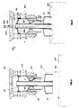
- the device for the automatic re-fill of the electrolyte and for the discharge of the fumes from electric accumulators which forms the object of the present invention is represented in its assembled form in Fig. 1, where it is marked with 3, and in an exploded view of the parts which constitute it in Fig. 2.
- said device comprises a body 10 which, as can be observed in the Figs. 3 and 4, can be sealingly matched into hole 2 of a lid 1 of an electric accumulator and it presents a cavity 11 limited by a bottom 101.
- Said body 10 presents laterally one or more first holes 12, opposite to one another and lying essentially on the same plane and one or more second holes 13, also opposite to one another, co-planar and lying on a plane which is lower than the plane on which said first holes 12 lie.
- Said holes are connected which ducts which allow the discharge of the fumes from the accumulator and the inlet of the re-fill liquid into the accumulator respectively.
- a tubular element 20 is attached to body 10.
- Said tubular element 20 consists of an outer tubular section 24 which is inserted into the cavity 11 of said body 10 and of a cylindrical guiding element 25 arranged co-axially within said outer tubular section 24.
- tubular element 20 presents laterally on its cylindrical wall one or more through-openings 23, each of which communicates with at least one of said one or more second holes 13 belonging to said body 10, when said tubular element 20 is matched with body 10 itself.
- the device according to the invention presents also a tubular stick 30 which is slidingly inserted into said through-hole 22 of said transversal surface 21.
- Said stick 30 presents at one end a floating body 31 which co-operates with the liquid contained within the accumulator, while at its other end there is a flexible membrane 40 which is connected with said tubular stick 30 by means of first sealingly locking means 32 and is also connected with the lateral inner surface of said tubular element 20 by means of second sealingly locking means 132.
- Said sealingly locking means consist of annular indentations 232 and 332 obtained in said tubular stick 30 and in said tubular element 20.
- said tubular stick 30 also presents, in an essentially intermediate position, closing means consisting of a shutter 33 in the shape of a truncated cone, suited to intercept said hole 22 of said transversal surface 21.
- closing means consisting of a shutter 33 in the shape of a truncated cone, suited to intercept said hole 22 of said transversal surface 21.
- the male thread 14 of body 10 of the device is tightened into the female thread 140 belonging to hole 2 drilled in lid 1, after an OR-ring 60 has been inserted into the annular seat 61 obtained in the outer part of body 10 and comprised between said first holes 12 and said first holes 13.
- thread 140 there is a sealing surface 200 which achieves the hermetic seal when it lies flush against wall 300 of body 10 of device 3.
- the thread may be replaced by pressure insertable means.
- each of said one or more holes 12 are in communication with first fume-discharging ducts 112 obtained in lid 1 and, in the same way, said one or more second holes 13 are in communication with second ducts 113 for the inlet of the re-fill liquid, which are also obtained in lid 1.
- the flexible membrane 40 defines within cavity 11 of body 10 of the device according to the invention an exhaust chamber 150 communicating with said one or more first holes 12 and with the end 130 of said tubular stick 30, on one side, and on the opposite side a chamber 50 for the build-up of the re-fill liquid, communicating with said one or more second holes 13. Therefore, as can be observed in the detail of Fig.
- said pressure 250 exerts on membrane 332 a force which is smaller that the total weight of said floating body 31, if the pressure of the liquid is not interrupted while the battery is in use. On the contrary, if the pressure of the liquid is interrupted, the pressure exerted on said membrane can be greater.
- Said additional force 332 due to the deformation of membrane 40 permits to obtain such closing pressure values on shutter 33, as to insure the tightness even with floats 31 having smaller diameters than the floats used with the automatic re-fill devices belonging to the known technique.
- FIG. 5 A different embodiment of the automatic re-fill device according to the invention is represented in Fig. 5, wherein said device is marked as a whole with 4 and wherein it can be observed that said first holes 120 for the discharge of the fumes and said second holes 130 for the inlet of the re-fill liquid communicate respectively with said first ducts 212 for the discharge of the fumes and with second ducts 213 for the inlet of the re-fill liquid belonging to body 100 of said device 4.
- Said ducts are provided with the hose connectors 312 and 313 suited to receive each a hose for the channeling of the exhaust fumes and of the re-fill liquid.
- the bottom 141 of body 100 of the device may also present a through-hole 242, said hole 242 allowing the introduction of a hydrometer for the electrolyte liquid.
- FIG. 10 Another embodiment of the automatic refill device according to the invention is represented in Fig. 10, wherein it can be observed that it is marked with 7 as a whole. It will be observed that in this embodiment the flexible membrane 740 is connected with the tubular stick 730 through first sealingly locking means 732, which consist of a pair of rings 741 and 742, placed opposite to each other and co-axial with the tubular stick 730, which catch between them the rim of the membrane 740 comprised between them.
- first sealingly locking means 732 consist of a pair of rings 741 and 742, placed opposite to each other and co-axial with the tubular stick 730, which catch between them the rim of the membrane 740 comprised between them.
- the flexible membrane 740 is also connected with the tubular element 720 through second sealingly locking means 832 which, as can be observed, are defined by the tilted plane 723 belonging to the tubular element 720 and by the corresponding shoulder 724 obtained in body 300 of the automatic re-fill device 7, between which the rim of membrane 740 corresponding with them is caught.
- the through-hole 722 drilled in the tubular element 720 is provided with a tapered seat 721 against which closing means contrast.
- Said closing means consist of a lip gasket in the shape of a truncated cone 821 which is pressed against a supporting ring 822 placed in an essentially central position in relation to said tubular stick 730.
- float 731 can be made in any dimension.
- Body 300 presents also sealing elements 600 and a lid 750 for stopping hole 760 for the fume exhaust.
- Another embodiment of the device may foresee for said through-hole 242, drilled at the bottom 141 of body 100 of said device, to be used as a hole for the exhaust of the fumes.
- body 100 of device 4 will present only said second holes 130 communicating with said second ducts 213 for the inlet of the re-fill liquid.
- all the embodiments present the flexible membrane which, by generating a force in addition to the pushing force generated by the floating status of the floating body, ensures the closing of the hole for the inlet of the re-fill liquid, even in the presence of vibrations in the accumulator during the re-fill operation.
- the re- fill device according to the invention may be applied both on accumulators with lids which allow the channeling of the exhaust fumes and of the re-fill liquid through channels belonging to the lids themselves and on lids for accumulators wherein the re-fill devices are fed through a flexible hose which is connected with the device through a hose connector.
- the device according to the invention in any of the embodiments which have been described may present a hole suited to allow the introduction of an instrument for measuring the density of the electrolyte, said hole being also suited to be used for the exhaust of the fumes during the re-fill operation.
Landscapes
- Chemical & Material Sciences (AREA)
- Chemical Kinetics & Catalysis (AREA)
- Electrochemistry (AREA)
- General Chemical & Material Sciences (AREA)
- Filling, Topping-Up Batteries (AREA)
- Supply Devices, Intensifiers, Converters, And Telemotors (AREA)
- Electrical Discharge Machining, Electrochemical Machining, And Combined Machining (AREA)
- Discharge Heating (AREA)
- Sealing Battery Cases Or Jackets (AREA)
- Gas Exhaust Devices For Batteries (AREA)
- Air Bags (AREA)
- Motor Or Generator Cooling System (AREA)
- Other Liquid Machine Or Engine Such As Wave Power Use (AREA)
Applications Claiming Priority (3)
| Application Number | Priority Date | Filing Date | Title |
|---|---|---|---|
| ITVI940139 | 1994-10-04 | ||
| IT94VI000139A IT1267859B1 (it) | 1994-10-04 | 1994-10-04 | Dispositivo di rabbocco e di sfiato per accumulatori elettrici |
| PCT/EP1995/003915 WO1996010846A1 (en) | 1994-10-04 | 1995-10-04 | A re-filling and fume-discharging device for electric accumulator batteries |
Publications (2)
| Publication Number | Publication Date |
|---|---|
| EP0784871A1 EP0784871A1 (en) | 1997-07-23 |
| EP0784871B1 true EP0784871B1 (en) | 1998-05-27 |
Family
ID=11425583
Family Applications (1)
| Application Number | Title | Priority Date | Filing Date |
|---|---|---|---|
| EP95934131A Expired - Lifetime EP0784871B1 (en) | 1994-10-04 | 1995-10-04 | A re-filling and fume-discharging device for electric accumulator batteries |
Country Status (14)
| Country | Link |
|---|---|
| US (1) | US5853913A (cs) |
| EP (1) | EP0784871B1 (cs) |
| JP (1) | JP2886689B2 (cs) |
| CN (1) | CN1159866A (cs) |
| AT (1) | ATE166750T1 (cs) |
| CA (1) | CA2200882A1 (cs) |
| CZ (1) | CZ286944B6 (cs) |
| DE (1) | DE69502732T2 (cs) |
| DK (1) | DK0784871T3 (cs) |
| ES (1) | ES2118628T3 (cs) |
| IT (1) | IT1267859B1 (cs) |
| SI (1) | SI9520105A (cs) |
| SK (1) | SK43397A3 (cs) |
| WO (1) | WO1996010846A1 (cs) |
Cited By (2)
| Publication number | Priority date | Publication date | Assignee | Title |
|---|---|---|---|---|
| DE102006054656A1 (de) * | 2006-06-09 | 2007-12-13 | Frötek - Vermögensverwaltung GmbH | Vorrichtung zum Verschließen und/oder zum Befüllen einer einzelnen galvanischen Zelle, Anordnung aus mehreren derartigen Verschlussvorrichtungen, Batterie und/oder Akkumulator zum Bereitstellen von Energie sowie Verfahren zum Ermitteln eines Zustandes einer Batterie und Verfahren zum Herstellen einer derartigen Vorrichtung |
| EP4465438A1 (en) * | 2023-05-18 | 2024-11-20 | Sovema Group S.P.A. | Cap for electrolyte cells and process for producing an electrolyte cell |
Families Citing this family (8)
| Publication number | Priority date | Publication date | Assignee | Title |
|---|---|---|---|---|
| IT1268417B1 (it) | 1994-10-11 | 1997-02-27 | Olimpio Stocchiero | Coperchio per accumulatori e dispositivi di carica cooperanti con detto coperchio |
| US6248138B1 (en) * | 1999-06-09 | 2001-06-19 | Delphi Technologies, Inc. | Activation and sealing of storage batteries |
| US6718996B2 (en) * | 2000-04-10 | 2004-04-13 | Club Car, Inc. | Filling pod for a battery, vehicle and method of supplying fluid to a battery |
| US6622744B2 (en) | 2000-04-10 | 2003-09-23 | Club Car, Inc. | Filling pod for a battery, vehicle and method of supplying fluid to a battery |
| US6786226B2 (en) * | 2000-04-10 | 2004-09-07 | Club Car, Inc. | Battery fluid supply system |
| JP5286800B2 (ja) * | 2008-01-25 | 2013-09-11 | 株式会社Gsユアサ | 蓄電池用液栓 |
| CN103745835B (zh) * | 2013-12-26 | 2016-08-17 | 宁波海融电器有限公司 | 一种电容器注液装置 |
| US12195270B2 (en) * | 2022-10-24 | 2025-01-14 | South 8 Technologies, Inc. | Mechanisms and methods for pressurized fluid injection and sealing |
Family Cites Families (8)
| Publication number | Priority date | Publication date | Assignee | Title |
|---|---|---|---|---|
| US1878223A (en) * | 1928-05-05 | 1932-09-20 | Woodbridge Joseph Lester | Filling device for battery cells |
| US1996843A (en) * | 1933-10-07 | 1935-04-09 | Jr Solomon L Van Meter | Battery filling device |
| GB451671A (en) * | 1935-02-09 | 1936-08-10 | Andrew Swan | Improvements in or relating to galvanic batteries |
| DE3539167A1 (de) * | 1984-11-09 | 1986-05-28 | Volkswagen AG, 3180 Wolfsburg | Einrichtung zur automatischen wasserbefuellung der zellen von elektrobatterien |
| EP0207346B1 (en) * | 1985-07-03 | 1990-10-31 | LA BATTERIA di M. TADIELLO S.r.l. | Plug for cells of electrical storage batteries |
| SE448650B (sv) * | 1985-08-14 | 1987-03-09 | Sab Nife Ab | Ventil for vattenpafyllning vid elektrokemiska ackumulatorbatterier |
| IT1204262B (it) * | 1986-01-29 | 1989-03-01 | Olimpio Stocchiero | Tappo per elementi di accumulatori con dispositivo di riempimento automatico |
| US4749633A (en) * | 1987-10-13 | 1988-06-07 | Elias Leonard W | Battery watering device |
-
1994
- 1994-10-04 IT IT94VI000139A patent/IT1267859B1/it active IP Right Grant
-
1995
- 1995-10-04 JP JP8511414A patent/JP2886689B2/ja not_active Expired - Lifetime
- 1995-10-04 ES ES95934131T patent/ES2118628T3/es not_active Expired - Lifetime
- 1995-10-04 WO PCT/EP1995/003915 patent/WO1996010846A1/en not_active Ceased
- 1995-10-04 CA CA002200882A patent/CA2200882A1/en not_active Abandoned
- 1995-10-04 CN CN95195505A patent/CN1159866A/zh active Pending
- 1995-10-04 AT AT95934131T patent/ATE166750T1/de not_active IP Right Cessation
- 1995-10-04 EP EP95934131A patent/EP0784871B1/en not_active Expired - Lifetime
- 1995-10-04 DE DE69502732T patent/DE69502732T2/de not_active Expired - Fee Related
- 1995-10-04 SK SK433-97A patent/SK43397A3/sk unknown
- 1995-10-04 US US08/809,776 patent/US5853913A/en not_active Expired - Fee Related
- 1995-10-04 SI SI9520105A patent/SI9520105A/sl unknown
- 1995-10-04 CZ CZ1997946A patent/CZ286944B6/cs not_active IP Right Cessation
- 1995-10-04 DK DK95934131T patent/DK0784871T3/da active
Cited By (2)
| Publication number | Priority date | Publication date | Assignee | Title |
|---|---|---|---|---|
| DE102006054656A1 (de) * | 2006-06-09 | 2007-12-13 | Frötek - Vermögensverwaltung GmbH | Vorrichtung zum Verschließen und/oder zum Befüllen einer einzelnen galvanischen Zelle, Anordnung aus mehreren derartigen Verschlussvorrichtungen, Batterie und/oder Akkumulator zum Bereitstellen von Energie sowie Verfahren zum Ermitteln eines Zustandes einer Batterie und Verfahren zum Herstellen einer derartigen Vorrichtung |
| EP4465438A1 (en) * | 2023-05-18 | 2024-11-20 | Sovema Group S.P.A. | Cap for electrolyte cells and process for producing an electrolyte cell |
Also Published As
| Publication number | Publication date |
|---|---|
| DE69502732T2 (de) | 1999-01-14 |
| CZ94697A3 (en) | 1997-10-15 |
| DK0784871T3 (da) | 1999-03-22 |
| JP2886689B2 (ja) | 1999-04-26 |
| SK43397A3 (en) | 1997-10-08 |
| CA2200882A1 (en) | 1996-04-11 |
| CN1159866A (zh) | 1997-09-17 |
| IT1267859B1 (it) | 1997-02-18 |
| ES2118628T3 (es) | 1998-09-16 |
| EP0784871A1 (en) | 1997-07-23 |
| WO1996010846A1 (en) | 1996-04-11 |
| JPH10502489A (ja) | 1998-03-03 |
| SI9520105A (en) | 1997-10-31 |
| ITVI940139A0 (it) | 1994-10-04 |
| ITVI940139A1 (it) | 1996-04-04 |
| CZ286944B6 (en) | 2000-08-16 |
| US5853913A (en) | 1998-12-29 |
| ATE166750T1 (de) | 1998-06-15 |
| DE69502732D1 (de) | 1998-07-02 |
Similar Documents
| Publication | Publication Date | Title |
|---|---|---|
| EP0784871B1 (en) | A re-filling and fume-discharging device for electric accumulator batteries | |
| EP0733272B1 (en) | Device to exhaust the fumes produced inside accumulator batteries | |
| US9153386B2 (en) | Electric storage device pressure regulating apparatus and electric storage device | |
| US6686720B2 (en) | Vented-type leak resistant motor cycle battery | |
| US6890681B2 (en) | Leak resistant automotive battery | |
| EP0234278B1 (en) | Cap for accumulators elements with device for automatic filling | |
| KR20080094062A (ko) | 힌지식 배터리 벤트 캡 및 이와 관련된 집합체의 벤트 어셈블리 | |
| CA2077203C (en) | Device for exhausting the fumes forming inside accumulator batteries | |
| EP0786152B1 (en) | A lid for accumulator batteries and charging devices co-operating with said lid | |
| US4147841A (en) | Vented container | |
| US1869258A (en) | Battery vent construction | |
| KR101969086B1 (ko) | 약품 용기 | |
| AU725492B2 (en) | Liquid filling device | |
| KR101840798B1 (ko) | 배관 연결부의 커버장치 | |
| EP0041334A1 (en) | Battery filling system | |
| KR101622129B1 (ko) | 충진밸브 어셈블리 | |
| FR2576149A1 (fr) | Soupape pour batteries etanches | |
| CN118117225A (zh) | 一种具有改进结构的密封件的电池 | |
| CN223408170U (zh) | 一种压液器以及出液装置 | |
| JP2005180614A (ja) | バルブ | |
| WO2011110668A1 (en) | Lid for a vrla battery | |
| KR102163629B1 (ko) | 커플러 | |
| JP2026510147A (ja) | 二次電池の電解液供給装置 | |
| JPH1149199A (ja) | 密閉缶への気体給排装置 | |
| JPS59120413A (ja) | 真空形成用栓 |
Legal Events
| Date | Code | Title | Description |
|---|---|---|---|
| PUAI | Public reference made under article 153(3) epc to a published international application that has entered the european phase |
Free format text: ORIGINAL CODE: 0009012 |
|
| 17P | Request for examination filed |
Effective date: 19970502 |
|
| AK | Designated contracting states |
Kind code of ref document: A1 Designated state(s): AT BE CH DE DK ES FR GB GR IE IT LI LU NL PT SE |
|
| GRAG | Despatch of communication of intention to grant |
Free format text: ORIGINAL CODE: EPIDOS AGRA |
|
| 17Q | First examination report despatched |
Effective date: 19970828 |
|
| GRAG | Despatch of communication of intention to grant |
Free format text: ORIGINAL CODE: EPIDOS AGRA |
|
| GRAH | Despatch of communication of intention to grant a patent |
Free format text: ORIGINAL CODE: EPIDOS IGRA |
|
| GRAH | Despatch of communication of intention to grant a patent |
Free format text: ORIGINAL CODE: EPIDOS IGRA |
|
| GRAA | (expected) grant |
Free format text: ORIGINAL CODE: 0009210 |
|
| AK | Designated contracting states |
Kind code of ref document: B1 Designated state(s): AT BE CH DE DK ES FR GB GR IE IT LI LU NL PT SE |
|
| REF | Corresponds to: |
Ref document number: 166750 Country of ref document: AT Date of ref document: 19980615 Kind code of ref document: T |
|
| REG | Reference to a national code |
Ref country code: CH Ref legal event code: EP |
|
| REF | Corresponds to: |
Ref document number: 69502732 Country of ref document: DE Date of ref document: 19980702 |
|
| ITF | It: translation for a ep patent filed | ||
| ET | Fr: translation filed | ||
| REG | Reference to a national code |
Ref country code: IE Ref legal event code: FG4D |
|
| REG | Reference to a national code |
Ref country code: CH Ref legal event code: NV Representative=s name: KIRKER & CIE SA |
|
| REG | Reference to a national code |
Ref country code: ES Ref legal event code: FG2A Ref document number: 2118628 Country of ref document: ES Kind code of ref document: T3 |
|
| REG | Reference to a national code |
Ref country code: PT Ref legal event code: SC4A Free format text: AVAILABILITY OF NATIONAL TRANSLATION Effective date: 19980824 |
|
| REG | Reference to a national code |
Ref country code: DK Ref legal event code: T3 |
|
| PLBE | No opposition filed within time limit |
Free format text: ORIGINAL CODE: 0009261 |
|
| STAA | Information on the status of an ep patent application or granted ep patent |
Free format text: STATUS: NO OPPOSITION FILED WITHIN TIME LIMIT |
|
| 26N | No opposition filed | ||
| PGFP | Annual fee paid to national office [announced via postgrant information from national office to epo] |
Ref country code: PT Payment date: 19991001 Year of fee payment: 5 |
|
| PGFP | Annual fee paid to national office [announced via postgrant information from national office to epo] |
Ref country code: IE Payment date: 19991005 Year of fee payment: 5 |
|
| PGFP | Annual fee paid to national office [announced via postgrant information from national office to epo] |
Ref country code: BE Payment date: 19991012 Year of fee payment: 5 |
|
| PGFP | Annual fee paid to national office [announced via postgrant information from national office to epo] |
Ref country code: GR Payment date: 19991015 Year of fee payment: 5 |
|
| PGFP | Annual fee paid to national office [announced via postgrant information from national office to epo] |
Ref country code: LU Payment date: 19991019 Year of fee payment: 5 |
|
| PGFP | Annual fee paid to national office [announced via postgrant information from national office to epo] |
Ref country code: AT Payment date: 19991020 Year of fee payment: 5 |
|
| PGFP | Annual fee paid to national office [announced via postgrant information from national office to epo] |
Ref country code: DK Payment date: 19991026 Year of fee payment: 5 |
|
| PGFP | Annual fee paid to national office [announced via postgrant information from national office to epo] |
Ref country code: CH Payment date: 20000121 Year of fee payment: 5 |
|
| PG25 | Lapsed in a contracting state [announced via postgrant information from national office to epo] |
Ref country code: LU Free format text: LAPSE BECAUSE OF NON-PAYMENT OF DUE FEES Effective date: 20001004 Ref country code: IE Free format text: LAPSE BECAUSE OF NON-PAYMENT OF DUE FEES Effective date: 20001004 Ref country code: DK Free format text: LAPSE BECAUSE OF NON-PAYMENT OF DUE FEES Effective date: 20001004 Ref country code: AT Free format text: LAPSE BECAUSE OF NON-PAYMENT OF DUE FEES Effective date: 20001004 |
|
| PG25 | Lapsed in a contracting state [announced via postgrant information from national office to epo] |
Ref country code: LI Free format text: LAPSE BECAUSE OF NON-PAYMENT OF DUE FEES Effective date: 20001031 Ref country code: GR Free format text: LAPSE BECAUSE OF NON-PAYMENT OF DUE FEES Effective date: 20001031 Ref country code: CH Free format text: LAPSE BECAUSE OF NON-PAYMENT OF DUE FEES Effective date: 20001031 Ref country code: BE Free format text: LAPSE BECAUSE OF NON-PAYMENT OF DUE FEES Effective date: 20001031 |
|
| BERE | Be: lapsed |
Owner name: STOCCHIERO OLIMPIO Effective date: 20001031 |
|
| PG25 | Lapsed in a contracting state [announced via postgrant information from national office to epo] |
Ref country code: PT Free format text: LAPSE BECAUSE OF NON-PAYMENT OF DUE FEES Effective date: 20010430 |
|
| REG | Reference to a national code |
Ref country code: DK Ref legal event code: EBP |
|
| REG | Reference to a national code |
Ref country code: CH Ref legal event code: PL |
|
| REG | Reference to a national code |
Ref country code: IE Ref legal event code: MM4A |
|
| PGFP | Annual fee paid to national office [announced via postgrant information from national office to epo] |
Ref country code: GB Payment date: 20011003 Year of fee payment: 7 |
|
| PGFP | Annual fee paid to national office [announced via postgrant information from national office to epo] |
Ref country code: SE Payment date: 20011005 Year of fee payment: 7 |
|
| PGFP | Annual fee paid to national office [announced via postgrant information from national office to epo] |
Ref country code: FR Payment date: 20011010 Year of fee payment: 7 |
|
| PGFP | Annual fee paid to national office [announced via postgrant information from national office to epo] |
Ref country code: DE Payment date: 20011022 Year of fee payment: 7 |
|
| PGFP | Annual fee paid to national office [announced via postgrant information from national office to epo] |
Ref country code: ES Payment date: 20011025 Year of fee payment: 7 |
|
| PGFP | Annual fee paid to national office [announced via postgrant information from national office to epo] |
Ref country code: NL Payment date: 20011031 Year of fee payment: 7 |
|
| REG | Reference to a national code |
Ref country code: GB Ref legal event code: IF02 |
|
| PG25 | Lapsed in a contracting state [announced via postgrant information from national office to epo] |
Ref country code: GB Free format text: LAPSE BECAUSE OF NON-PAYMENT OF DUE FEES Effective date: 20021004 |
|
| PG25 | Lapsed in a contracting state [announced via postgrant information from national office to epo] |
Ref country code: SE Free format text: LAPSE BECAUSE OF NON-PAYMENT OF DUE FEES Effective date: 20021005 Ref country code: ES Free format text: LAPSE BECAUSE OF NON-PAYMENT OF DUE FEES Effective date: 20021005 |
|
| PG25 | Lapsed in a contracting state [announced via postgrant information from national office to epo] |
Ref country code: NL Free format text: LAPSE BECAUSE OF NON-PAYMENT OF DUE FEES Effective date: 20030501 Ref country code: DE Free format text: LAPSE BECAUSE OF NON-PAYMENT OF DUE FEES Effective date: 20030501 |
|
| GBPC | Gb: european patent ceased through non-payment of renewal fee |
Effective date: 20021004 |
|
| EUG | Se: european patent has lapsed | ||
| PG25 | Lapsed in a contracting state [announced via postgrant information from national office to epo] |
Ref country code: FR Free format text: LAPSE BECAUSE OF NON-PAYMENT OF DUE FEES Effective date: 20030630 |
|
| NLV4 | Nl: lapsed or anulled due to non-payment of the annual fee |
Effective date: 20030501 |
|
| REG | Reference to a national code |
Ref country code: FR Ref legal event code: ST |
|
| REG | Reference to a national code |
Ref country code: ES Ref legal event code: FD2A Effective date: 20031112 |
|
| PG25 | Lapsed in a contracting state [announced via postgrant information from national office to epo] |
Ref country code: IT Free format text: LAPSE BECAUSE OF NON-PAYMENT OF DUE FEES;WARNING: LAPSES OF ITALIAN PATENTS WITH EFFECTIVE DATE BEFORE 2007 MAY HAVE OCCURRED AT ANY TIME BEFORE 2007. THE CORRECT EFFECTIVE DATE MAY BE DIFFERENT FROM THE ONE RECORDED. Effective date: 20051004 |