EP0781679B1 - Système de commande pour la sécurisation d'un véhicule rapide, notamment guidé par un opérateur embarqué ou non dans ledit véhicule, installation pour le guidage d'un véhicule et procédé de commande d'un véhicule par un système correspondant - Google Patents
Système de commande pour la sécurisation d'un véhicule rapide, notamment guidé par un opérateur embarqué ou non dans ledit véhicule, installation pour le guidage d'un véhicule et procédé de commande d'un véhicule par un système correspondant Download PDFInfo
- Publication number
- EP0781679B1 EP0781679B1 EP19960402697 EP96402697A EP0781679B1 EP 0781679 B1 EP0781679 B1 EP 0781679B1 EP 19960402697 EP19960402697 EP 19960402697 EP 96402697 A EP96402697 A EP 96402697A EP 0781679 B1 EP0781679 B1 EP 0781679B1
- Authority
- EP
- European Patent Office
- Prior art keywords
- vehicle
- operator
- instruction
- longitudinal
- cref1
- Prior art date
- Legal status (The legal status is an assumption and is not a legal conclusion. Google has not performed a legal analysis and makes no representation as to the accuracy of the status listed.)
- Expired - Lifetime
Links
- 238000009434 installation Methods 0.000 title claims description 36
- 238000000034 method Methods 0.000 title claims description 6
- 238000010200 validation analysis Methods 0.000 claims description 35
- 238000006073 displacement reaction Methods 0.000 claims description 24
- 230000005540 biological transmission Effects 0.000 claims description 17
- 230000004044 response Effects 0.000 claims description 13
- 238000005516 engineering process Methods 0.000 claims description 9
- 108010077333 CAP1-6D Proteins 0.000 claims description 5
- 108010031970 prostasin Proteins 0.000 claims description 5
- 238000001514 detection method Methods 0.000 claims description 4
- 101710180456 CD-NTase-associated protein 4 Proteins 0.000 claims description 3
- 102100026548 Caspase-8 Human genes 0.000 claims description 3
- 230000008859 change Effects 0.000 claims description 3
- 238000004891 communication Methods 0.000 claims description 3
- 239000000835 fiber Substances 0.000 claims description 3
- 230000000877 morphologic effect Effects 0.000 claims description 3
- 238000012546 transfer Methods 0.000 claims description 3
- 230000009347 mechanical transmission Effects 0.000 claims description 2
- 102100033082 TNF receptor-associated factor 3 Human genes 0.000 claims 2
- 238000001454 recorded image Methods 0.000 claims 1
- 238000012795 verification Methods 0.000 claims 1
- 230000006978 adaptation Effects 0.000 description 39
- 101100129496 Arabidopsis thaliana CYP711A1 gene Proteins 0.000 description 14
- 101100129499 Arabidopsis thaliana MAX2 gene Proteins 0.000 description 14
- 101100083446 Danio rerio plekhh1 gene Proteins 0.000 description 14
- 230000006870 function Effects 0.000 description 10
- 102100032919 Chromobox protein homolog 1 Human genes 0.000 description 7
- 101000797584 Homo sapiens Chromobox protein homolog 1 Proteins 0.000 description 7
- 230000001133 acceleration Effects 0.000 description 7
- 230000011514 reflex Effects 0.000 description 7
- 230000009471 action Effects 0.000 description 6
- 210000000056 organ Anatomy 0.000 description 6
- 101000908384 Bos taurus Dipeptidyl peptidase 4 Proteins 0.000 description 4
- 102100026620 E3 ubiquitin ligase TRAF3IP2 Human genes 0.000 description 4
- 101710140859 E3 ubiquitin ligase TRAF3IP2 Proteins 0.000 description 4
- HEFNNWSXXWATRW-UHFFFAOYSA-N Ibuprofen Chemical compound CC(C)CC1=CC=C(C(C)C(O)=O)C=C1 HEFNNWSXXWATRW-UHFFFAOYSA-N 0.000 description 4
- 230000004807 localization Effects 0.000 description 4
- 101150079344 ACT4 gene Proteins 0.000 description 3
- 101150024393 ACT5 gene Proteins 0.000 description 3
- 102100031102 C-C motif chemokine 4 Human genes 0.000 description 3
- 101000897856 Homo sapiens Adenylyl cyclase-associated protein 2 Proteins 0.000 description 3
- 101000836079 Homo sapiens Serpin B8 Proteins 0.000 description 3
- 101000798702 Homo sapiens Transmembrane protease serine 4 Proteins 0.000 description 3
- 101000777470 Mus musculus C-C motif chemokine 4 Proteins 0.000 description 3
- 102100029500 Prostasin Human genes 0.000 description 3
- 101100492334 Saccharomyces cerevisiae (strain ATCC 204508 / S288c) ARP1 gene Proteins 0.000 description 3
- 101100056774 Saccharomyces cerevisiae (strain ATCC 204508 / S288c) ARP3 gene Proteins 0.000 description 3
- 102100032471 Transmembrane protease serine 4 Human genes 0.000 description 3
- 230000008901 benefit Effects 0.000 description 3
- 238000012937 correction Methods 0.000 description 3
- 230000007246 mechanism Effects 0.000 description 3
- 238000012800 visualization Methods 0.000 description 3
- 101100536354 Drosophila melanogaster tant gene Proteins 0.000 description 2
- 101000836075 Homo sapiens Serpin B9 Proteins 0.000 description 2
- 101000661807 Homo sapiens Suppressor of tumorigenicity 14 protein Proteins 0.000 description 2
- 102100037942 Suppressor of tumorigenicity 14 protein Human genes 0.000 description 2
- 238000004364 calculation method Methods 0.000 description 2
- 230000003287 optical effect Effects 0.000 description 2
- 230000006641 stabilisation Effects 0.000 description 2
- 238000011105 stabilization Methods 0.000 description 2
- 206010003830 Automatism Diseases 0.000 description 1
- 101000957437 Homo sapiens Mitochondrial carnitine/acylcarnitine carrier protein Proteins 0.000 description 1
- 102100038738 Mitochondrial carnitine/acylcarnitine carrier protein Human genes 0.000 description 1
- 238000013459 approach Methods 0.000 description 1
- 230000001143 conditioned effect Effects 0.000 description 1
- 230000001186 cumulative effect Effects 0.000 description 1
- 230000003247 decreasing effect Effects 0.000 description 1
- 230000001419 dependent effect Effects 0.000 description 1
- 238000011161 development Methods 0.000 description 1
- 238000010586 diagram Methods 0.000 description 1
- 230000007613 environmental effect Effects 0.000 description 1
- 238000004519 manufacturing process Methods 0.000 description 1
- 230000007935 neutral effect Effects 0.000 description 1
- 230000010355 oscillation Effects 0.000 description 1
- 230000008447 perception Effects 0.000 description 1
- 238000002360 preparation method Methods 0.000 description 1
- 230000009467 reduction Effects 0.000 description 1
- 230000001052 transient effect Effects 0.000 description 1
- 230000001960 triggered effect Effects 0.000 description 1
Images




Classifications
-
- B—PERFORMING OPERATIONS; TRANSPORTING
- B60—VEHICLES IN GENERAL
- B60W—CONJOINT CONTROL OF VEHICLE SUB-UNITS OF DIFFERENT TYPE OR DIFFERENT FUNCTION; CONTROL SYSTEMS SPECIALLY ADAPTED FOR HYBRID VEHICLES; ROAD VEHICLE DRIVE CONTROL SYSTEMS FOR PURPOSES NOT RELATED TO THE CONTROL OF A PARTICULAR SUB-UNIT
- B60W40/00—Estimation or calculation of non-directly measurable driving parameters for road vehicle drive control systems not related to the control of a particular sub unit, e.g. by using mathematical models
- B60W40/02—Estimation or calculation of non-directly measurable driving parameters for road vehicle drive control systems not related to the control of a particular sub unit, e.g. by using mathematical models related to ambient conditions
-
- B—PERFORMING OPERATIONS; TRANSPORTING
- B60—VEHICLES IN GENERAL
- B60K—ARRANGEMENT OR MOUNTING OF PROPULSION UNITS OR OF TRANSMISSIONS IN VEHICLES; ARRANGEMENT OR MOUNTING OF PLURAL DIVERSE PRIME-MOVERS IN VEHICLES; AUXILIARY DRIVES FOR VEHICLES; INSTRUMENTATION OR DASHBOARDS FOR VEHICLES; ARRANGEMENTS IN CONNECTION WITH COOLING, AIR INTAKE, GAS EXHAUST OR FUEL SUPPLY OF PROPULSION UNITS IN VEHICLES
- B60K31/00—Vehicle fittings, acting on a single sub-unit only, for automatically controlling vehicle speed, i.e. preventing speed from exceeding an arbitrarily established velocity or maintaining speed at a particular velocity, as selected by the vehicle operator
- B60K31/0066—Vehicle fittings, acting on a single sub-unit only, for automatically controlling vehicle speed, i.e. preventing speed from exceeding an arbitrarily established velocity or maintaining speed at a particular velocity, as selected by the vehicle operator responsive to vehicle path curvature
-
- B—PERFORMING OPERATIONS; TRANSPORTING
- B60—VEHICLES IN GENERAL
- B60W—CONJOINT CONTROL OF VEHICLE SUB-UNITS OF DIFFERENT TYPE OR DIFFERENT FUNCTION; CONTROL SYSTEMS SPECIALLY ADAPTED FOR HYBRID VEHICLES; ROAD VEHICLE DRIVE CONTROL SYSTEMS FOR PURPOSES NOT RELATED TO THE CONTROL OF A PARTICULAR SUB-UNIT
- B60W40/00—Estimation or calculation of non-directly measurable driving parameters for road vehicle drive control systems not related to the control of a particular sub unit, e.g. by using mathematical models
- B60W40/10—Estimation or calculation of non-directly measurable driving parameters for road vehicle drive control systems not related to the control of a particular sub unit, e.g. by using mathematical models related to vehicle motion
-
- B—PERFORMING OPERATIONS; TRANSPORTING
- B60—VEHICLES IN GENERAL
- B60W—CONJOINT CONTROL OF VEHICLE SUB-UNITS OF DIFFERENT TYPE OR DIFFERENT FUNCTION; CONTROL SYSTEMS SPECIALLY ADAPTED FOR HYBRID VEHICLES; ROAD VEHICLE DRIVE CONTROL SYSTEMS FOR PURPOSES NOT RELATED TO THE CONTROL OF A PARTICULAR SUB-UNIT
- B60W50/00—Details of control systems for road vehicle drive control not related to the control of a particular sub-unit, e.g. process diagnostic or vehicle driver interfaces
- B60W50/08—Interaction between the driver and the control system
-
- G—PHYSICS
- G05—CONTROLLING; REGULATING
- G05D—SYSTEMS FOR CONTROLLING OR REGULATING NON-ELECTRIC VARIABLES
- G05D1/00—Control of position, course, altitude or attitude of land, water, air or space vehicles, e.g. using automatic pilots
- G05D1/0011—Control of position, course, altitude or attitude of land, water, air or space vehicles, e.g. using automatic pilots associated with a remote control arrangement
- G05D1/0038—Control of position, course, altitude or attitude of land, water, air or space vehicles, e.g. using automatic pilots associated with a remote control arrangement by providing the operator with simple or augmented images from one or more cameras located onboard the vehicle, e.g. tele-operation
-
- B—PERFORMING OPERATIONS; TRANSPORTING
- B63—SHIPS OR OTHER WATERBORNE VESSELS; RELATED EQUIPMENT
- B63H—MARINE PROPULSION OR STEERING
- B63H25/00—Steering; Slowing-down otherwise than by use of propulsive elements; Dynamic anchoring, i.e. positioning vessels by means of main or auxiliary propulsive elements
- B63H25/02—Initiating means for steering, for slowing down, otherwise than by use of propulsive elements, or for dynamic anchoring
- B63H2025/026—Initiating means for steering, for slowing down, otherwise than by use of propulsive elements, or for dynamic anchoring using multi-axis control levers, or the like, e.g. joysticks, wherein at least one degree of freedom is employed for steering, slowing down, or dynamic anchoring
Definitions
- the invention relates to a system for controlling the engine and steering members of a vehicle, an installation for guiding a vehicle and a method for controlling a vehicle, for securing a fast vehicle, in particular guided by an operator on board or not in said vehicle, according to the preamble of claim 1.
- document GB-A-2,095,350 describes a servomechanism which develops an actuator setpoint for the organ motor taking into account relative reference instructions longitudinal and transverse movements of the vehicle as well as signals representative of the longitudinal displacements and transverse of the vehicle.
- Such a servomechanism makes it possible to control only the longitudinal displacement (using actuation on brake control). However, even if it takes into account the distance between a longitudinal axis and the vehicle, control transverse movement of the vehicle is not allowed but is carried out by the driver on board the vehicle. It results in insufficient and incomplete automatic security vehicle stability, especially at high speed longitudinal.
- the Applicant has posed the problem of providing a servomechanism capable of securing, even at high longitudinal speed, the longitudinal and transverse displacements of the vehicle.
- the control device performs an adaptation of said longitudinal speed coupled to a command of the steering unit, so that the setpoint-actuator transverse relative to the transverse displacement of the vehicle, rejoin, as quickly as possible, the deposit of transverse reference relative to the transverse displacement of the vehicle, while respecting certain characteristics of the vehicle and / or the environment in which it is traveling.
- first instruction for reference that associated with the longitudinal speed of the vehicle
- second reference setpoint that associated with transverse movement of the vehicle
- first setpoint-actuator that relating to the motor organ
- second setpoint-actuator that relating to the steering member
- first signal received that representative of the speed current longitudinal
- second signal received that representative of the current curvature (wheel angle) of the vehicle
- the instructions for reference most often correspond to instructions from an operator, or are calculated from these operator instructions.
- step c) further provides, in the presence of a first higher reference reference received or equal to the first maximum allowable value calculated, to declare that an adaptation is in progress and initialize the value of the previous first actuator setpoint according to the first current actuator setpoint just being so determined.
- the characteristics relating to the vehicle are chosen from the group formed by the characteristics geometric, morphological, dynamic and attitude of the vehicle, and the previous first and second instructions for reference received.
- the first sensor means include at minus one instrument chosen from the group formed by an encoder on a drive shaft or on a wheel, a tachometer, and similar.
- the second means sensors include at least one instrument chosen from the group formed by a wheel angle encoder, a potentiometer wheel angle, and the like.
- the first actuator means include at minus one organ chosen from the group formed by a chain of brake, accelerator, gearbox control, of the transfer case, of the transmission chain vehicle mechanics, and the like.
- the second means actuators include at least one member selected from the group formed by a vehicle steering wheel control chain, and the like.
- the vehicle control means include a computer embedded.
- the first and second actuator means, as well as the engine and steering components of the vehicle constitute active means of the vehicle capable of delivering respectively a signal representative of the position and / or the current state of said active means, and the device for command further comprises means for receiving the signals delivered by said active means of the vehicle.
- the present invention also relates to an installation for guiding a vehicle, by an on-board operator or not in said vehicle according to claim 12, and which is characterized by the fact the vehicle is equipped with the control system described above.
- the vehicle control means thus make it possible to ensure functions from which the operator is thus relieved.
- a such an installation makes it possible in particular to reduce the load of operator's job, reduce volume and frequency information passing between the vehicle and the station, and thereby limit the risk of information overload operator, source of fatigue and risk (non-perception danger, even misinterpretation of information returned).
- the means of selection and validation are suitable for selecting a predetermined mode of mobility of the vehicle, chosen in the group formed by the mobility mode on points Passage, segment mobility mode, mobility mode on command in yaw and mode of mobility on command in yaw speed.
- the means of selection and validation include a keyboard or the like for choosing the mode of vehicle mobility.
- the means of selection and validation include a handle manipulator for selection and validation of certain operator instructions and a joystick associated with the selection and validation of the operator instruction relative to the longitudinal cruising speed of the vehicle.
- the manipulator handle includes means suitable for designating in the image visualized an operator segment of variable length, having first and second movable ends, the end initial mobile being connected to a fixed point of the image corresponding to a chosen fixed point of the vehicle and the end final defining the point of the environment where the vehicle must go and stop.
- the handle manipulator is suitable for being moved straight and / or rotated by the operator along the orthogonal axes X, Y, and Z, separately and / or cumulative.
- the handle manipulator is suitable for being moved by the operator along the Y axis perpendicular to the axis longitudinal displacement of the vehicle, to move the end of the operator segment along the Y axis, the segment-operator being parallel to the longitudinal axis of the vehicle.
- the handle manipulator is adapted to be moved by the operator along the X axis parallel to the axis of longitudinal movement of the vehicle, to move the end end of the operator segment along the X axis, the operator segment being parallel to the longitudinal axis of the vehicle.
- the handle manipulator is specific to be rotated by the operator relative to the perpendicular Z axis to the longitudinal axis of movement of the vehicle, to apply curvature to the initial and final ends of the operator segment with respect to the Z axis.
- step i) further comprises the step which consists in determining an operating margin granted by the operator to the vehicle in the servo on the operator segment thus validated and step ii) consists in taking into account of this operator margin in the servo-control of the vehicle.
- the handle manipulator in the mode of mobility on command in yaw speed, in combination with the selection and validation of an operator instruction relating to the longitudinal cruising speed of the vehicle, is suitable for being moved by the operator along the Y axis perpendicular to the axis of movement longitudinal of the vehicle, to apply an operator instruction relating to the yaw speed of the vehicle in a first yaw speed range, while the manipulator is suitable for being rotated by the operator in relation to the Z axis perpendicular to the longitudinal displacement axis of the vehicle, to apply a relative operator instruction at yaw speed in a second speed range different from the first range.
- the handle manipulator comprises means allowing, when moving the vehicle, to pass from mobility mode on yaw speed command to mode mobility on yaw command and vice versa.
- the handle manipulator in the mode of mobility on crossing points, includes means suitable for designating on the displayed image at least one point defining the point of the environment where the vehicle must go and stop.
- the mode of mobility on crossing points further includes autonomous behavior of the vehicle of the swerve type, set up automatically or in response to an operator command, in order to avoid an obstacle the optionally.
- the station's transmission / reception means and of the vehicle communicate with each other using appropriate and chosen communication in the group formed by radio frequency technology, wired fiber technology optical or electrical wire, and the like.
- At certain instruction-operator of certain mode of mobility is associated with a distance of validity corresponding to the spatial validity of said operator instruction and in the absence of at least one new operator instructions at the end of the validity distance, the control means-vehicle trigger stopping the vehicle until at least one new operator instruction.
- the present invention also relates to a method of control of a vehicle implemented by the command described above.
- the reference VH designates a land vehicle guided by a guide installation according to the invention.
- the VH land vehicle may be a propulsion vehicle thermal or electric, equipped with conventional means of this kind of vehicle. It has an autonomous mode in which he is likely to be guided by an on-board operator or not in the vehicle.
- the land vehicle can also be a specific mobile robot.
- the land vehicle is equipped with ACT1 actuator means of the motor member and of ACT2 actuator means of the member of management.
- the actuator means ACT1 include at least one organ chosen from the group formed by a chain ACT3 brake, ACT5 accelerator, ACT4 gearbox, transfer box, mechanical transmission chain of the vehicle, and the like.
- the actuator means ACT2 comprise at minus one organ chosen from the group formed by a chain of vehicle steering wheel control or the like.
- control means are provided for secure the fast movement of the vehicle.
- control means control, in addition to the actuator means mentioned above, sensor means CAP1 and CAP2 capable of capturing and delivering, in real time, respectively a first signal S1 representative of the speed current longitudinal of the vehicle, and a second signal S2 representative of the current transverse displacement of the vehicle.
- COMV control means are bidirectionally connected to the actuator means ACT1 and ACT2 mentioned above.
- a signal representative of a CACT actuator setpoint is routed, while in the direction means actuators to control means, a signal representative of the position and / or the current state of said actuator means is transmitted RCACT.
- This RCACT signal representative of the position and / or the state actuator means designates the return of the actuator setpoint. It is routed to the control means.
- the ACT3 brake control chain receives the setpoint-actuator CACT3, and delivers in return The signal RCACT3.
- the sensor means CAP1 comprise at least one instrument chosen from the group formed by a tree encoder transmission or on wheel, a tachometer, and the like.
- CAP2 sensor means include at least one instrument chosen from the group formed by a wheel angle encoder, a wheel angle potentiometer and the like.
- the COMV control means receive first and second reference instructions CREF1 and CREF2 (calculated at least in part from operator instructions which will be described in more detail below), with a view to ordering respectively the driving and steering components of the vehicle and develop, in real time, the first and second CACT1 and CACT2 actuator setpoints according to a servomechanism taking into account at least the first and second signals received S1 and S2 and first and second reference instructions CREF1 and CREF2 thus received.
- first and second reference instructions CREF1 and CREF2 (calculated at least in part from operator instructions which will be described in more detail below)
- the control of the motor component ACT1 of the vehicle is carried out at least using the command chain of ACT3 brake, ACT4 gearbox, and accelerator ACT5.
- the servomechanism calculates the actuator setpoints at any time CACT3, CACT4, and CACT5 associated respectively with the ACT3 brake control chain, of the gearbox ACT4, and the ACT5 accelerator.
- a servomechanism is provided according to the invention in which in response to the second reference setpoint CREF2, the control means adapts, in real time, the first actuator setpoint CACT1 up to that the second actuator setpoint CACT2 corresponds to the second reference reference CREF2.
- the means of COMV control carry out an adjustment of the longitudinal speed coupled with a command from the management body, so that the CACT2 actuator setpoint rallies, the more quickly possible, the relative reference setpoint CREF2 transverse displacement, while respecting certain dynamic constraints of the vehicle, as well as some characteristics of the environment in which it occurs moves.
- the adaptation of the first actuator setpoint CACT1 is performed here according to steps a) to c) until the second CACT2 actuator setpoint most closely matches quickly possible at the second reference reference CREF2 in accordance with steps d) to f), while respecting certain characteristics of the vehicle and / or the environment in which it moves.
- the servomechanism includes two operations mutuals.
- the first step is to adapt the current vehicle speed at the curvature specified by the operator while the second step is to adapt the angle of rotation of the steering wheel at current speed and reciprocally.
- This servomechanism actually consists of a reflex action implemented by the control means to secure the vehicle in case of excess heavy demand by the operator.
- control means according to the invention can be transposed to driving a conventional vehicle in which the operator is on board the vehicle and uses the servomechanism according to the invention in a way similar to ABS ("Anti-blocking System").
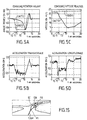
- FIGS. 5A to 5D chronograms have been represented which illustrate the action of speed adaptation in accordance to the invention.
- the vehicle in response to a "steering wheel kick" (instruction operator for the preparation of the second setpoint reference) at a current longitudinal speed S1 of 80 km / h, the vehicle, equipped with the servomechanism according to the invention, reacts to act on the brake control (first setpoint-actuator) to stabilize the acceleration transverse of the vehicle.
- This stabilization of transverse acceleration results from appropriate control the vehicle wheel angle (second setpoint-actuator) which turns the wheels of the vehicle safely while consistency with current vehicle speed.
- the operator's intention (steering wheel kick at 80 km / h) is well taken into account (here a sudden deviation from the trajectory on one side), but its realization is secure. He is at notice that this adaptation mechanism can also be implemented to help the operator negotiate a turn, approached at too high speed.
- the reference setpoint CREF2 relating to the transverse displacement of the vehicle calculated from the operator instruction "steering wheel kick” is shown in line dashed while the CACT2 actuator setpoint relating to transverse displacement is shown in strong lines.
- the CACT2 setpoint meets gradually (here during an interval of 6 s) the value CREF2 setpoint.
- This time interval is variable. he can be determined according to a specific law taking into account characteristics of the vehicle as well as those of the environment in which it moves.
- the longitudinal speed current If and the reference setpoint CREF1 are substantially constant around 23 m / sec.
- the servomechanism acts on the CACT1 actuator setpoint (here braking) in order to reach a speed of the order of 5 m / sec, approximately 6 seconds after actuation of the blow wheel.
- Figures 5B and 5D illustrate the transverse accelerations and longitudinal of the vehicle during the adaptation of speed according to the invention.
- the safety servomechanism relating to the adaptation of speed affects both the transverse displacement and stabilization of the longitudinal speed of the vehicle.
- the transverse servo-control here limits, at all times, the wheel angle setpoint achievable according to constraints momentum.
- the calculation of the values MAX1 and MAX2 maximum allowances take into account vehicle and / or environmental specifications in which it moves. These characteristics are relating to the current context. More specifically, the characteristics related to the vehicle are selected from the group formed by geometric, morphological characteristics, dynamic, and attitude (emanating from a CAP3 type sensor inertial unit capable of picking up a representative S3 signal the current attitude of the vehicle (pitch, roll, orientation, orientation speed and orientation acceleration)) of the vehicle, and the previous first and second reference instructions received.
- One of the advantages of the speed adaptation according to the invention is to be easy to set up. Indeed, if the operator is surprised by the appearance of an obstacle to avoid, by example on its trajectory, it solicits (reflex action) strongly the transverse movement of the vehicle (blow of steering wheel) and the servomechanism according to the invention described above takes place immediately.
- servomechanism speed adaptation mode taking hysteresis into account servomechanism.
- While in the presence of a first reference setpoint received greater than or equal to the first maximum value admissible calculated and corrected MAX1-HYST1, it is planned to take into account the first actuator setpoint CACT1, the minimum value chosen from the group formed by said first calculated maximum admissible value MAX1, the first reference setpoint received CREF1 and the previous first setpoint-actuator OLDCACT1, and initialize the value of the previous first actuator instruction to that of the first current actuator setpoint OLDCACT1 CACT1.
- the COMV control means comprise at least an on-board computer or the like.
- the calculator is of type 68XXX from MOTOROLA.
- the operator OP is located in a remote station ST of the vehicle.
- the invention relates to an installation for guidance in which it is intended to equip the vehicle with control means described above and which develop the first and second setpoint-actuator CACT1 and CACT2 in response to the first and second CREF1 reference instructions and CREF2 calculated at least in part from operator instructions COP from the operator, via the station.
- the shooting means include 4 cameras, one oriented in the forward direction of movement of the vehicle, one oriented in the rear direction of movement of the vehicle, and two laterally oriented.
- the remote station ST (figure 17), it is provided, as a corollary, for transmission / reception-station means with the vehicle, to receive IMG images transmitted by the vehicle, as well as the RCACT information, S1, S2 and S3 delivered by the active means and sensors of the vehicle, and to transmit operator instructions to the vehicle COP.
- the station is equipped with display means VIEW of the images thus received.
- the means display include 3 video screens, central screen being associated with the broadcasting of images from cameras oriented in the direction of travel of the vehicle (forward direction and rear) and the side screens being associated with the broadcast of images from side cameras.
- SEL selection and validation means allow the operator to select and validate at least some COP operator instructions relating to vehicle movement, using the IMG visualized image, and information RCACT, S1, S2 and S3 from the active means of the vehicle as well as sensor means CAP1, CAP2 and CAP3.
- COMS station control means control the means of visualization, means of selection and validation, as well as the station's transmission / reception means.
- the vehicle vehicle location means capable of capture and deliver S4 information relating to the vehicle location.
- These localization means include CAP4 sensor means connected to the vehicle control means COMV which manage the S4 information thus captured.
- the CAP4 sensor means are of the GPS type ("Global Positioning System”) or positioning tag absolute.
- means are provided for generate information relating to the current location of the vehicle based on the information received in order to participate in developing at least some operator instructions TJOP and SGOP which will be described in more detail below.
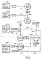
- the SEL selection and validation means allow the operator to select and validate a mobility mode MOD chosen of the vehicle. So he can choose a mode of mobility among the group formed by the mobility mode on MOD1 waypoints, the mobility mode on MOD2 segment, MOD3 shoelace mobility mode and mobility on command in yaw speed MOD4.
- Each of these layers has setpoint-operator interfaces which can be directly used by the operator to implement functions without having to use higher order functions.
- the different modes are listed here by level of automation descending.
- the mode with the most automatic level higher is MOD1 mode.
- the mobility mode at crossing points is a so-called "remote control” which consists in remotely moving a vehicle by controlling the TJOP trajectory on which it controls.
- the operator thus specifies a series of waypoints. he it is a progression by leaps and bounds.
- the MOD2 mobility mode, on segment is also a behavior "remote control" in which the operator specifies a SGOP objective segment on which the vehicle is controlled.
- MOD3 and MOD4 mobility modes belong to the "remote control", in which it is planned to move to distance a vehicle by controlling its longitudinal movements and transverse.
- LOP yaw or yaw rate VLOP associated with a longitudinal displacement speed VOP (possibly supplemented by a rallying acceleration of speed).
- the yaw of the vehicle is understood here to mean the orientation of said vehicle in the environment in which it moves.
- the vehicle yaw may be different from the course of the vehicle, as long as it does not depend on a benchmark magnetic or whatever.
- a CLA keyboard or similar at the ST station To choose the vehicle's mobility mode, a CLA keyboard or similar at the ST station.
- SEL selection and validation means there a joystick type manipulator is also provided JOY for the selection and validation of certain COP operator instructions and a MAN controller associated with the selection and validation of the operator instruction relating to the cruising speed of the VOP vehicle.
- FIGS. 6A and 6B a manipulator has been shown. handle.
- This handle is equipped with a GA trigger dedicated in particular to the validation of the operator instructions and of a start button PC load.
- the end of the handle is equipped with a MOL wheel dedicated in particular to the mobility mode on MOD2 segment as well than a send / cancel button MA dedicated in particular to the mode mobility at MOD1 crossing points.
- the JOY handle manipulator in the mobility mode on the MOD2 segment, includes means of designating a segment on the image displayed SGOP operator of variable length, having first EX1 and second movable ends EX2.
- the initial end EX1 is connected to a fixed point PF of the image corresponding to a fixed point chosen from the vehicle.
- the EX2 endpoint defines the point of the environment where the vehicle should go and stop.
- the operator specifies the general direction he wishes to see taken vehicle by designating directly from a video image, a line segment SGOP on which the vehicle will control as if it were a trajectory.
- the vehicle also takes into account a cruising speed VOP, which he will endeavor to respect, while adapting under current conditions.
- step i) further comprises the step which consists in determining an operating margin granted by the operator to the vehicle in the servo on the operator segment thus validated and step ii) consists in taking into account of this operator margin in the servo-control of the vehicle.
- This operator margin is a distance that indicates the latitude granted by the operator to the vehicle in the servo on the objective segment.
- This margin can be variable, i.e. by a value determined at the option of the operator, or fixed, determined by default by the control means.
- the different successive values of the reference setpoints CREF1 and CREF2 are developed and issued to a frequency of the order of 5 to 10 Hz, compatible with the frequency of information transmission / reception means between the station and the vehicle.
- Control means implemented at vehicle level are constantly looking to follow the objective SGOP segment thus selected and validated at the station level, and transmitted to the vehicle control means.
- the vehicle control means determine, depending on the current speed S1 of the vehicle, one point target on the SGOP objective segment, towards which the means of vehicle-control control the yaw of the vehicle (setpoint-actuator yaw CACT2 to rally by the organs engine and steering).
- the speed adopted on the course tends to reach the specified VOP cruising speed, taking into account instantaneous constraints (dynamic type of vehicle or position quality delivered by the location system) and absolute (at all times, the vehicle must be able come to a stop without exceeding the end point of segment EX2).
- the means of transmitting / receiving the vehicle and of the station use radio frequency technology in which the COP operator instructions are punctually transmitted or periodically, to the vehicle up to a frequency of the order of 5 to 10 Hz.
- the vehicle continues its progression to come to a stop on the EX2 extreme point of the last objective segment received SGOP.
- the operator can send operator instructions to the frequency he wishes, according to his different tasks.
- the operator designates directly the operator segment SGOP on the video image displayed on his VISU monitor. For this, it positions at using the handle manipulator, a colored cursor indicating the end of the EX2 segment.
- the VOP speed setpoint is specified by a joystick type (like a throttle on an airplane), which maintains the VOP speed setpoint even without intervention operator. This is an advantage in the as far as remote control can be done now with legs free from any task.
- the designation of the operator segment can be done according to two types of handle manipulator movements that are non-exclusive, namely the trajectory deviation (along the axis Y) or the curvature (along the Z axis).
- the handle manipulator can be moved by the operator along a Y axis perpendicular to the axis of longitudinal displacement of the vehicle.
- the displacement along the Y axis of the manipulator at handle moves the final EX2 end of the segment operator along the Y axis. Note that in this mode of mobility, the operator segment thus designated is parallel to the longitudinal axis of the vehicle.
- the manipulator handle is suitable for being turned by the operator by relative to a Z axis perpendicular to the axis of displacement longitudinal of the vehicle, to apply a curvature to initial EX1 and final EX2 ends of the operator segment SGOP with respect to the Z axis.
- the handle manipulator is also likely to be moved by the operator along an axis X parallel to the axis of longitudinal movement of the vehicle, to move the end final EX2 of the operator segment along the X axis, the end initial moving away in proportion to the action of the operator.
- the MO dial is associated here for fine correction on the X axis.
- Sending the objective segment SGOP to the vehicle is conditioned operator action on the manipulator trigger with handle (validation).
- the operator can thus control the vehicle by validating a segment in real time. For this, it is enough to maintain the trigger permanently validated.
- Figures 10 to 13 illustrate the negotiation of a turn in remote control by objective segments.
- the vehicle is stopped at approaching the turn, the operator then designates a segment SGOP before sending it to the vehicle ( Figure 10).
- the SGOP segment becomes the vehicle mobility directive. It is linked to the terrain and is displayed ( Figures 11 to 13) in a color other than that of the segment in the operation selection and designation (figure 10).
- the vehicle begins to slave on the setpoint trajectory defined by the operator segment SGOP validated, the operator designating the next segment.
- the vehicle After validation of the new segment by the operator, the vehicle is slaved to the new segment thus validated.
- the operator can also keep the trigger, it then guides the vehicle in real time, slightest movement of its handle manipulator causing thus an evolution of the vehicle as a result.
- the vehicle continues to run along the last requested objective segment, until stopping at its point extreme.
- the manipulator handle in combination with selection and validation of an operator instruction relating to speed longitudinal cruise of the VOP vehicle, is suitable for being moved by the operator according to the Y axis perpendicular to the axis of the longitudinal displacement of the vehicle, to apply a relative operator instruction at the yaw rate of the VLOP vehicle in a first PG1 yaw speed range, while the manipulator can be turned by the operator relative to the axis Z perpendicular to the axis of the longitudinal displacement of the vehicle, to apply an operator instruction relating to the VLOP yaw speed in a second PG2 speed range different from the first PG1 range.
- control of the transverse displacement in mode of MOD4 mobility uses both transverse Y and Z axes of the handle manipulator.
- the Y axis (right / left) controls full dynamic PG1 of the vehicle (full range of rotation of the steering wheel). It is the preferred command for the maneuver, the low speeds and heavy loads on the vehicle (abrupt change of trajectory).
- the Z axis of rotation specifies a correction of transverse displacement using only a small percentage of the PG2 domain. This is the command reserved for corrections of medium and high speed trajectory, allowing finely rectify a trajectory at high speed, without provoke the reflex action of adaptation.
- the handle manipulator only controls movement here transverse of the vehicle, the cruising speed VOP of the vehicle is specified via the type lever throttle. Taking into account the position of this throttle is subject for safety reasons PC support for the handle manipulator by the operator.
- VOP speed setpoint is generated here from the same as a remote control by speed control lace (MOD4 mode).
- MOD3 yaw control here consists of a setpoint orientation of the longitudinal axis of the vehicle relatively at its current orientation. Such an approach allows not need real heading information and absolute (magnetic or geographic) within the installation.
- the current orientation ID1 of the vehicle is here an information embedded in the video image. It is generated thanks location information from the vehicle.
- a new ID3 yaw setpoint is sent to the vehicle and displayed on the H horizon.
- the vehicle controls the yaw of the vehicle on the deposit ID3, and thus steer the vehicle in the required direction.
- This command is particularly suitable for progression outside the road context, by successive landmarks in a landscape.
- the setpoint becomes a yaw speed, thereby obtaining the full vehicle dynamics.
- VOP MOD4 and MOD3 mobility modes reaching the vehicle, is associated with spatial validity.
- This spatial validity corresponds to the validity of a distance for the associated operator setpoint VOP. So in the absence of at least one new VOP operator instruction at the outcome of the journey of the validity distance associated with the previous operator instruction, the means of controlling the vehicle stop the vehicle until receipt at least one new operator instruction.
- this spatial validity consists of a distance dependent on the value of the VOP operator setpoint. This spatial validity is representative of confidence that the operator has in the trajectory that he asks the vehicle (depending on its current visibility distance).
- the order of magnitude of this distance of reference for a VOP speed setpoint of 1 m / sec is about 1 m, while it is 5 m for a set point of VOP speed of the order of 22 m / sec.
- the validation of points is effective through the trigger.
- the MA button in the "send” position allows you to send all the points thus validated towards the vehicle.
- the button in the "cancel” position allows you to cancel one at minus the points of the trajectory.
- the vehicle In MOD1 mode, the vehicle is slaved on the operator path TJOP respecting an associated margin. The vehicle is therefore free to go where it wants as long as its deviation from the trajectory remains less than this servo margin.
- this MOD1 mobility mode on points of passage additionally includes autonomous behavior of the swerve type vehicle.
- reflex action of the type lurch This autonomous behavior is called reflex action of the type lurch. It can be automatic or in response to the operator control, in order to avoid an obstacle the case applicable.
- a swerve consists, when detecting an obstacle on the immediate trajectory of the vehicle, to perform an EC deviation (decided and managed in coherence with the dynamic potential of the vehicle) with respect to the TJOP operator trajectory, so as to avoid the obstacle while respecting the margin specified.
- This autonomous mode requires the equipment of detection means at vehicle level suitable for detecting an obstacle on the operator trajectory of the vehicle.
- These detection means are for example of the radar type, infrared sensor, ultrasonic sensor, scanning laser.
- the operator has the possibility to react quickly to mobility conditions (occurrence of a particular event such as an obstacle on the trajectory for example), controlling a operator swerve consisting of a gap in speed and / or transverse compared to current setpoints used by the vehicle.
- the vehicle interprets this information in the same way that during a swerve triggered automatically at the onset of an obstacle, and manages the dynamics of the deviation of secure way.
- the means of transmitting / receiving information between the station and the vehicle can use any technology, for example radio frequency technology, technology wired to optical or electric fiber, or the like.
Landscapes
- Engineering & Computer Science (AREA)
- Automation & Control Theory (AREA)
- Transportation (AREA)
- Mechanical Engineering (AREA)
- Physics & Mathematics (AREA)
- Mathematical Physics (AREA)
- Radar, Positioning & Navigation (AREA)
- Remote Sensing (AREA)
- Combustion & Propulsion (AREA)
- Chemical & Material Sciences (AREA)
- Human Computer Interaction (AREA)
- Aviation & Aerospace Engineering (AREA)
- General Physics & Mathematics (AREA)
- Steering Control In Accordance With Driving Conditions (AREA)
- Control Of Driving Devices And Active Controlling Of Vehicle (AREA)
- Control Of Vehicle Engines Or Engines For Specific Uses (AREA)
- Traffic Control Systems (AREA)
- Control Of Position, Course, Altitude, Or Attitude Of Moving Bodies (AREA)
Description
- a) calculer une première valeur maximale admissible pour la première consigne de référence, selon une première loi dépendant des premier et second signaux captés et de caractéristiques relatives au véhicule et/ou à l'environnement dans lequel il se déplace,
- b) comparer la première valeur maximale admissible avec la première consigne de référence reçue,
- c) en présence d'une première consigne de référence reçue inférieure à la première valeur maximale admissible calculée, prendre en compte la première consigne de référence reçue comme première consigne-actionneur, tandis qu'en présence d'une première consigne de référence reçue supérieure ou égale à la première valeur maximale admissible calculée, prendre en compte ladite première valeur calculée comme première consigne-actionneur,
- d) calculer une seconde valeur maximale admissible pour la seconde consigne de référence, selon une seconde loi dépendant des premier et second signaux captés et des caractéristiques relatives au véhicule, et/ou à l'environnement dans lequel il se déplace,
- e) comparer la seconde valeur maximale admissible calculée avec la seconde consigne de référence reçue,
- f) en présence d'une seconde consigne de référence reçue inférieure à la seconde valeur maximale admissible calculée, prendre en compte la seconde consigne de référence reçue comme seconde consigne-actionneur, tandis qu'en présence d'une seconde consigne de référence reçue supérieure ou égale à la seconde valeur calculée, prendre en compte ladite seconde valeur calculée comme seconde consigne-actionneur,
- b1) déterminer une valeur constante représentative de l'hystérésis du servomécanisme d'adaptation de vitesse,
- b2) comparer la première valeur maximale admissible calculée et corrigée selon la valeur d'hystérésis prédéterminée avec la première consigne de référence reçue,
- c1) en présence d'une première consigne de référence reçue inférieure à ladite première valeur maximale admissible calculée et corrigée, prendre la première consigne de référence reçue comme première consigne-actionneur et déclarer la fin de l'adaptation, tandis qu'en présence d'une première consigne de référence reçue supérieure ou égale à la première valeur maximale admissible calculée et corrigée, prendre en compte comme première consigne-actionneur la valeur minimum choisie parmi le groupe formé par ladite première valeur maximum admissible calculée, la première consigne de référence reçue et la précédente première consigne-actionneur, et initialiser la valeur de la précédente première consigne-actionneur à celle de la première consigne-actionneur courante.
- des moyens de commande-véhicule propres à élaborer, à cadence choisie, les première et seconde consignes-actionneur en réponse aux première et seconde consignes de référence calculées au moins en partie à partir de consignes-opérateur émanant de l'opérateur, via la station,
- des moyens de prises de vues pour enregistrer des images de l'environnement dans lequel le véhicule se déplace,
- des moyens d'émission/réception-véhicule d'informations avec la station distante, pour transmettre les images enregistrées à la station distante, ainsi que les informations délivrées par les moyens actifs et capteurs du véhicule et pour recevoir les consignes-opérateur émanant de l'opérateur, via la station,
- des moyens d'émission/réception-station d'informations avec le véhicule, pour recevoir les images transmises par le véhicule ainsi que les informations délivrées par les moyens actifs et capteurs du véhicule, et pour transmettre au véhicule les consignes-opérateur,
- des moyens de visualisation des images ainsi reçues,
- des moyens de sélection et de validation propres à valider au moins certaines consignes-opérateur relatives au déplacement du véhicule, à l'aide de l'image visualisée, et des informations provenant des moyens actifs et capteurs du véhicule, et
- des moyens de commande-stationpropres à piloter les moyens de visualisation, les moyens de sélection et de validation, ainsi que les moyens d'émission/réception de la station.
- des moyens de localisation du véhicule propres à capter et délivrer des informations relatives à la localisation du véhicule, et
- des moyens propres à générer sur l'image visualisée des informations relatives à la position courante du véhicule en fonction des informations de localisation ainsi reçues, en vue de participer à l'élaboration de certaines au moins des consignes-opérateur.
- i) au niveau de l'opérateur, sélectionner et valider sur l'image visualisée un segment-opérateur de longueur et orientation choisies, et transmettre aux moyens de commande du véhicule, le segment-opérateur ainsi sélectionné et validé, et
- ii) au niveau des moyens de commande-véhicule, calculer, à cadence choisie, les valeurs des différentes première et seconde consignes de référence en fonction des consignes-opérateur ainsi reçues, et déterminer les première et seconde consignes-actionneur en fonction des première et seconde consignes de référence ainsi calculées.
- 1) prévoir sur l'image visualisée, un axe formant horizon virtuel pour le véhicule dans l'environnement dans lequel il se déplace,
- 2) prévoir sur l'horizon, un premier indicateur propre à se déplacer le long dudit horizon et à indiquer le lacet courant du véhicule sur ledit horizon,
- 3) prévoir sur l'horizon, un second indicateur propre à se déplacer le long dudit horizon, et à indiquer le reflet de la position courante du manipulateur à poignée,
- 4) prévoir sur l'horizon, un troisième indicateur propre à se déplacer le long dudit horizon, et à indiquer la consigne-opérateur relative au lacet du véhicule, et
- 5) sélectionner et valider à l'aide du manipulateur, la consigne-opérateur relative au lacet, à l'aide des premier et second indicateurs.
- désigner dans l'image visualisée une pluralité de points de passage formant une trajectoire-opérateur, le véhicule devant aller et s'arrêter au dernier point de la trajectoire-opérateur,
- valider la totalité ou une partie de la trajectoire-opérateur ainsi désignée, et
- au niveau des moyens de commande-véhicule, élaborer, à cadence choisie, les différentes première et seconde consignes de référence en fonction de la trajectoire-opérateur ainsi validée et de la position courante du véhicule.
- prévoir des moyens de détection propres à détecter un obstacle sur la trajectoire-opérateur du véhicule,
- effectuer un écart par rapport à la trajectoire-opérateur du véhicule de manière à éviter l'obstacle ainsi détecté, tout en respectant la marge-opérateur, l'écart étant réalisé à une vitesse longitudinale compatible avec les caractéristiques du véhicule et/ou de l'environnement dans lequel il se déplace,
- maintenir l'écart jusqu'au dépassement de l'obstacle, et
- retourner à la trajectoire-opérateur du véhicule après dépassement.
- sur l'image visualisée, par l'opérateur, en réponse à un événement choisi, déterminer un écart-opérateur par rapport à la trajectoire-opérateur,
- élaborer, à cadence choisie, les différentes première et seconde consignes de référence en tenant compte dudit écart-opérateur ainsi déterminé, de la trajectoire-opérateur et de la position courante du véhicule.
- la figure 1 est une vue schématique des moyens essentiels et constitutifs de l'installation de guidage entre un véhicule terrestre et une station distante selon l'invention;
- la figure 2 est un organigramme illustrant différents modes de mobilité du véhicule et leurs consignes-opérateur associées selon l'invention;
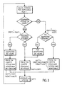
- la figure 3 est un organigramme illustrant l'adaptation de vitesse longitudinale selon l'invention;
- la figure 4 est un organigramme illustrant l'adaptation du déplacement transversal selon l'invention;
- les figures 5A à 5D sont des chronogrammes illustrant l'adaptation de la vitesse en réponse à un coup de volant selon l'invention;
- les figures 6A et 6B sont des vues schématiques du manipulateur à poignée selon l'invention;
- les figures 7A et 7B représentent schématiquement le déplacement du manipulateur à poignée pour désigner le segment opérateur selon l'axe Y selon l'invention;
- les figures 8A et 8B représentent schématiquement le déplacement du manipulateur à poignée pour désigner selon l'axe Z le segment-opérateur selon l'invention;
- les figures 9A et 9B représentent schématiquement le déplacement du manipulateur à poignée pour désigner, selon l'axe des X, le segment-opérateur selon l'invention;
- les figures 10 à 13 représentent des images illustrant la négociation d'un virage en mode de mobilité sur segment selon l'invention;
- la figure 14 représente schématiquement l'image visualisée de l'environnement dans lequel se déplace le véhicule avec incrustation des indicateurs en mode de mobilité en lacet;
- la figure 15 illustre schématiquement l'image visualisée illustrant la réalisation d'une embardée automatique selon l'invention;
- la figure 16 est une vue d'un véhicule terrestre équipé du dispositif de commande selon l'invention; et
- la figure 17 est vue schématique du poste opérateur situé dans la station distante selon l'invention.
- a) calculer une première valeur maximale admissible MAX1 pour la première consigne de référence CREF1, selon une première loi L1 dépendant des premier et second signaux captés S1 et S2 et de caractéristiques relatives au véhicule VH et/ou à l'environnement dans lequel il se déplace;
- b) comparer la première valeur maximale admissible MAX1 avec la première consigne de référence reçue CREF1;
- c) en présence d'une première consigne de référence reçue CREF1 inférieure à la première valeur maximale admissible calculée MAX1, prendre en compte la première consigne de référence reçue CREF1 comme première consigne-actionneur CACT1, tandis qu'en présence d'une première consigne de référence reçue CREF1 supérieure ou égale à la première valeur maximale admissible calculée, prendre en compte ladite première valeur calculée MAX1 comme première consigne-actionneur CACT1,
- d) calculer une seconde valeur maximale admissible MAX2 pour la seconde consigne de référence CREF2, selon une seconde loi L2 dépendant des premier et second signaux captés S1 et S2 et des caractéristiques relatives au véhicule, et/ou à l'environnement dans lequel il se déplace,
- e) comparer la seconde valeur maximale admissible calculée MAX2 avec la seconde consigne de référence reçue CREF2,
- f) en présence d'une seconde consigne de référence reçue CREF2 inférieure à la seconde valeur maximale admissible calculée MAX2, prendre en compte la seconde consigne de référence reçue CREF2 comme seconde consigne-actionneur CACT2, tandis qu'en présence d'une seconde consigne de référence reçue CREF2 supérieure ou égale à la seconde valeur calculée MAX2, prendre en compte ladite seconde valeur calculée MAX2 comme seconde consigne-actionneur CACT2.
MAX2 : angle de roues maximum autorisé lié aux contraintes dynamiques,
βcons : consigne d'angle de roues envoyée par l'opérateur (ou issue de la consigne de l'opérateur). Elle prend en compte les contraintes géométriques du véhicule (braquage maximum),
γt : accélération transversale maximum autorisée pour le véhicule,
l : empattement du véhicule,
S1 : vitesse courante du véhicule,
MAX1 : vitesse maximum admissible par le véhicule liée au comportement courant du déplacement transversal (intention de l'opérateur).
- b1) déterminer une valeur constante (par exemple 1 m/s) représentative de l'hystérésis du servomécanisme d'adaptation vitesse HYST1;
- b2) comparer la première valeur maximale admissible calculée et corrigée selon la valeur d'hystérésis prédéterminée MAX1-HYST1 avec la première consigne de référence reçue CREF1.
- c1) en présence d'une première consigne de référence reçue CREF1 inférieure à ladite première valeur maximale admissible calculée et corrigée MAX1-HYST1, prendre la première consigne de référence reçue CREF1 comme première consigne-actionneur CACT1 et déclarer la fin de l'adaptation.
- 1) prévoir sur l'image visualisée, un axe H formant horizon virtuel pour le véhicule dans l'environnement dans lequel il se déplace,
- 2) prévoir sur l'horizon H, un premier indicateur ID1 propre à se déplacer le long dudit horizon et à indiquer le lacet courant LC du véhicule sur ledit horizon,
- 3) prévoir sur l'horizon H, un second indicateur ID2 propre à se déplacer le long dudit horizon H, et à indiquer le reflet de la position courante du manipulateur à poignée JOY,
- 4) prévoir sur l'horizon H, un troisième indicateur ID3 propre à se déplacer le long dudit horizon, et à indiquer la consigne-opérateur relative au lacet du véhicule LOP, et
- 5) sélectionner et valider à l'aide du manipulateur JOY, la consigne-opérateur relative au lacet LOP à l'aide des premier et second indicateurs ID1 et ID2.
- désigner dans l'image visualisée une pluralité de points de passage P1, P2 formant une trajectoire-opérateur TJOP, le véhicule devant aller et s'arrêter au dernier point P2 de la trajectoire-opérateur;
- valider la totalité ou une partie de la trajectoire-opérateur TJOP ainsi désignée, et
- au niveau des moyens de commande-véhicule, élaborer les première et seconde consignes de référence CREF1 et CREF2 en fonction de la trajectoire-opérateur TJOP ainsi validée, et de la position courante du véhicule.
- si nécessaire, freinage sur la trajectoire-opérateur TJOP tant que l'embardée n'est pas décrétée possible;
- écart de trajectoire à vitesse stabilisée, dépendant de la taille de l'obstacle et de sa position par rapport à la trajectoire;
- maintien de l'écart jusqu'au dépassement de l'obstacle;
- retour à la trajectoire-opérateur d'origine, après dépassement.
Claims (36)
- Système de commande des organes moteur et de direction d'un véhicule (VH) du type comprenant :caractérisé en ce que ledit servomécanisme, en réponse à une seconde consigne de référence transversale (CREF2) incompatible avec la vitesse longitudinale courante du véhicule (S1), adapte, en temps réel, et en couple avec une commande de l'organe de direction, la première consigne-actionneur longitudinale (CACT1) jusqu'à ce que la seconde consigne-actionneur transversale (CACT2) corresponde, le plus rapidement possible, à la seconde consigne de référence transversale (CREF2), ce qui permet de sécuriser, même à grande vitesse longitudinale, les déplacements longitudinal et transversal du véhicule.des premiers moyens capteurs (CAP1) captant, et délivrant, en temps réel, un premier signal (S1) représentatif de la vitesse longitudinale courante du véhicule,des seconds moyens capteurs (CAP2) captant, et délivrant, en temps réel, un second signal (S2) représentatif du déplacement transversal courant du véhicule,des premiers moyens actionneurs (ACT1) de l'organe moteur en fonction d'une première consigne-actionneur longitudinale choisie (CACT1),des seconds moyens actionneurs (ACT2) de l'organe de direction en fonction d'une seconde consigne-actionneur transversale choisie (CACT2), etdes moyens de commande-véhicule (COMV) recevant des première et seconde consignes de référence longitudinale et transversale (CREF1 et CREF2) en vue de commander respectivement les organes moteur et de direction et élaborant en temps réel, les première et seconde consigne-actionneur longitudinale et transversale (CACT1 et CACT2) selon un servomécanisme tenant compte des premier et second signaux captés (S1 et S2) et des première et seconde consignes de référence longitudinale et transversale reçues (CREF1 et CREF2),
- Système selon la revendication 1, caractérisé en ce que le servomécanisme d'adaptation de vitesse comprend les étapes suivantes:l'adaptation de la première consigne-actionneur (CACT1) étant réalisée à tout instant conformément aux étapes a) à c) jusqu'à ce que la seconde consigne-actionneur (CACT2) corresponde, le plus rapidement possible, à la seconde consigne de référence (CREF2) conformément aux étapes d) à f), tout en respectant certaines au moins des caractéristiques du véhicule et/ou de l'environnement dans lequel il se déplace.a) calculer une première valeur maximale admissible (MAX1) pour la première consigne de référence (CREF1), selon une première loi (L1) dépendant des premier et second signaux captés (S1 et S2) et de caractéristiques relatives au véhicule (VH) et/ou à l'environnement dans lequel il se déplace,b) comparer la première valeur maximale admissible (MAX1) avec la première consigne de référence reçue (CREF1),c) en présence d'une première consigne de référence reçue (CREF1) inférieure à la première valeur maximale admissible calculée (MAX1), prendre en compte la première consigne de référence reçue (CREF1) comme première consigne-actionneur (CACT1), tandis qu'en présence d'une première consigne de référence reçue (CREF1) supérieure ou égale à la première valeur maximale admissible calculée, prendre en compte ladite première valeur calculée (MAX1) comme première consigne-actionneur (CACT1),d) calculer une seconde valeur maximale admissible (MAX2) pour la seconde consigne de référence (CREF2), selon une seconde loi (L2) dépendant des premier et second signaux captés (S1 et S2) et des caractéristiques relatives au véhicule, et/ou à l'environnement dans lequel il se déplace,e) comparer la seconde valeur maximale admissible calculée (MAX2) avec la seconde consigne de référence reçue (CREF2),f) en présence d'une seconde consigne de référence reçue (CREF2) inférieure à la seconde valeur maximale admissible calculée (MAX2), prendre en compte la seconde consigne de référence reçue (CREF2) comme seconde consigne-actionneur (CACT2), tandis qu'en présence d'une seconde consigne de référence reçue (CREF2) supérieure ou égale à la seconde valeur calculée (MAX2), prendre en compte ladite seconde valeur calculée (MAX2) comme seconde consigne-actionneur (CACT2),
- Système selon la revendication 2, caractérisé en ce qu'en l'absence d'adaptation de vitesse longitudinale en cours, l'étape c) prévoit en outre, en présence d'une première consigne de référence reçue (CREF1) supérieure ou égale à la première valeur maximale admissible calculée (MAX1), de déclarer qu'une adaptation est en cours et d'initialiser la valeur de la précédente première consigne-actionneur (OLDCACT1) selon la première consigne-actionneur courante venant d'être déterminée (OLDCACT1=CACT1).
- Système selon la revendication 3, caractérisé en ce qu'en présence d'une adaptation de vitesse en cours, l'étape b) comprend les étapes suivantes:en ce que l'étape c) comprend l'étape suivante:b1) déterminer une valeur constante représentative de l'hystérésis du servomécanisme d'adaptation de vitesse (HYST1),b2) comparer la première valeur maximale admissible calculée et corrigée selon la valeur d'hystérésis prédéterminée (MAX1-HYST1) avec la première consigne de référence reçue (CREF1),c1) en présence d'une première consigne de référence reçue (CREF1) inférieure à ladite première valeur maximale admissible calculée et corrigée (MAX1-HYST1), prendre la première consigne de référence reçue (CREF1) comme première consigne-actionneur (CACT1) et déclarer la fin de l'adaptation, tandis qu'en présence d'une première consigne de référence reçue (CREF1) supérieure ou égale à la première valeur maximale admissible calculée et corrigée (MAX1-HYST1), prendre en compte comme première consigne-actionneur (CACT1) la valeur minimum choisie parmi le groupe formé par ladite première valeur maximum admissible calculée (MAX1), la première consigne de référence reçue (CREF1) et la précédente première consigne-actionneur (OLDCACT1), et initialiser la valeur de la précédente première consigne-actionneur à celle de la première consigne-actionneur courante (OLDCACT1=CACT1).
- Système selon la revendication 2, caractérisé en ce que les caractéristiques relatives au véhicule (VH) sont choisies dans le groupe formé par les caractéristiques géométriques, morphologiques, dynamiques ou d'attitude du véhicule (VH), et les précédentes première et seconde consignes de référence reçues (CREF1 et CREF2).
- Système selon la revendication 1, caractérisé en ce que les premiers moyens capteurs (CAP1) comprennent au moins un instrument choisi dans le groupe formé par un codeur sur arbre de transmission ou sur roue, un tachymètre, et analogue.
- Système selon la revendication 1, caractérisé en ce que les seconds moyens capteurs (CAP2) comprennent au moins un instrument choisi dans le groupe formé par un codeur d'angle de roue, un potentiomètre d'angle de roue, et analogue.
- Système selon la revendication 1, caractérisé en ce que les premiers moyens actionneurs (ACT1) comprennent au moins un organe choisi dans le groupe formé par une chaíne de commande du frein (ACT3), de l'accélérateur (ACT5), de la boíte de vitesse (ACT4), de la boíte de transfert, ou de la chaíne de transmission mécanique du véhicule, et analogue.
- Système selon la revendication 1, caractérisé en ce que les seconds moyens actionneurs (ACT2) comprennent au moins un organe choisi dans le groupe formé par une chaíne de commande du volant du véhicule, et analogue.
- Système selon la revendication 1, caractérisé en ce que les moyens de commande du véhicule (COMV) comprennent un calculateur embarqué.
- Système selon l'une des revendication 1 à 10, caractérisé en ce que les moyens actionneurs (ACT1, ACT2), ainsi que les organes moteur et de direction du véhicule constituent des moyens actifs du véhicule propres à délivrer respectivement un signal (RCACT) représentatif de la position et/ou de l'état courant desdits moyens actifs, et en ce qu'il comprend en outre des moyens de réception des signaux délivrés par lesdits moyens actifs du véhicule.
- Installation pour le guidage d'un véhicule (VH) par un opérateur (OP) embarqué ou non dans ledit véhicule, caractérisée en ce que le véhicule (VH) est équipé du système de commande selon l'une des revendications 1 à 11.
- Installation selon la revendication 12, dans laquelle l'opérateur (OP) est situé dans une station distante (ST) du véhicule, caractérisée en ce qu'elle comprend, embarqués sur le véhicule (VH):en ce qu'elle comprend au niveau de la station distante (ST):des moyens de commande-véhicule (COMV) propres à élaborer, à cadence choisie, les première et seconde consignes-actionneur (CACT1 et CACT2) en réponse aux première et seconde consignes de référence (CREF1 et CREF2) calculées au moins en partie à partir de consignes-opérateur (COP) émanant de l'opérateur, via la station,des moyens de prises de vues (PV) pour enregistrer des images de l'environnement (IMG) dans lequel le véhicule (VH) se déplace, etdes moyens d'émission/réception-véhicule d'informations avec la station distante (ST), pour transmettre les images enregistrées à la station distante, ainsi que les informations délivrées par les moyens actifs et capteurs du véhicule et pour recevoir les consignes-opérateur (COP) émanant de l'opérateur via la station,des moyens d'émission/réception-station d'informations avec le véhicule (VH), pour recevoir les images (IMG) transmises par le véhicule ainsi que les informations délivrées par les moyens actifs et capteurs du véhicule, et pour transmettre au véhicule les consignes-opérateur (COP),des moyens de visualisation (VISU) des images ainsi reçues,des moyens de sélection et de validation (SEL) propres à sélectionner et valider au moins certaines consignes-opérateur (SGOP,VOP,VLOP,TJOP,LOP) relatives au déplacement du véhicule, à l'aide de l'image visualisée (IMG), et des informations provenant des moyens actifs et capteurs du véhicule, etdes moyens de commande-station (COMS) propres à piloter les moyens de visualisation, les moyens de sélection et de validation, ainsi que les moyens d'émission/réception de la station.
- Installation selon la revendication 13, caractérisée en ce qu'elle comprend en outre, embarqués dans le véhicule:dans la station distante:des moyens de localisation (CAP4) du véhicule propres à capter et délivrer des informations (S4) relatives à la localisation du véhicule, etdes moyens propres à générer sur l'image visualisée des informations relatives à la position courante du véhicule en fonction des informations de localisation ainsi reçues, en vue de participer à l'élaboration de certaines au moins des consignes-opérateur (SGOP,TJOP).
- Installation selon la revendication 13, caractérisée en ce que les moyens de sélection (SEL) sont propres à sélectionner un mode de mobilité (MOD) prédéterminé du véhicule, choisi dans le groupe formé par le mode de mobilité sur points de passage (MOD1), le mode de mobilité sur segment (MOD2), le mode de mobilité sur commande en lacet (MOD3) et le mode de mobilité sur commande en vitesse de lacet (MOD4).
- Installation selon la revendication 15, caractérisée en ce que chaque mode de mobilité (MOD) est exclusif, l'un par rapport à l'autre.
- Installation selon la revendication 15, caractérisée en ce que les moyens de sélection et de validation (SEL) comprennent un clavier ou analogue (CLA) pour choisir le mode de mobilité (MOD) du véhicule.
- Installation selon la revendication 15, caractérisée en ce que les moyens de sélection et de validation (SEL) comprennent un manipulateur à poignée (JOY) pour la sélection et la validation de certaines consignes-opérateur (VLOP,LOP,TJOP,SGOP) et une manette (MAN) associée à la sélection et la validation de la consigne-opérateur relative à la vitesse longitudinale de croisière du véhicule (VOP).
- Installation selon les revendications 15 et 18, caractérisée en ce que, dans le mode de mobilité sur segment (MOD2) le manipulateur à poignée (JOY) comprend des moyens propres à désigner sur l'image visualisée un segment-opérateur (SGOP) de longueur variable, ayant des première (EX1) et seconde extrémités mobiles (EX2), l'extrémité mobile initiale (EX1) étant reliée à un point fixe (PF) de l'image correspondant à un point fixe choisi du véhicule et l'extrémité finale (EX2) définissant le point de l'environnement où le véhicule doit aller et s'arrêter.
- Installation selon la revendication 19, caractérisée en ce que le mode de mobilité sur segment (MOD2) comprend, en association avec la sélection et la validation d'une consigne-opérateur relative à la vitesse longitudinale de croisière du véhicule (VOP), les étapes suivantes:i) au niveau de l'opérateur, sélectionner et valider sur l'image visualisée un segment-opérateur d'une longueur et orientation choisies (SGOP), et transmettre aux moyens de commande-véhicule (COMV), le segment-opérateur ainsi sélectionné et validé (SGOP), etii) au niveau des moyens de commande-véhicule (COMV), calculer, à cadence choisie, les valeurs des différentes première et seconde consignes de référence (CREF1 et CREF2) en fonction des consignes-opérateur ainsi reçues (SGOP et VOP), et déterminer les première et seconde consignes-actionneur (CACT1 et CACT2) en fonction des première et seconde consignes de référence ainsi calculées (CREF1 et CREF2).
- Installation selon la revendication 20, caractérisée en ce que le manipulateur à poignée est propre à être déplacé par l'opérateur selon un axe Y perpendiculaire à l'axe de déplacement longitudinal du véhicule, pour déplacer l'extrémité finale (EX2) du segment-opérateur (SGOP) selon l'axe Y, le segment-opérateur (SGOP) étant parallèle à l'axe longitudinal du véhicule.
- Installation selon la revendication 20 ou la revendication 21, caractérisée en ce que le manipulateur à poignée est propre à être déplacé par l'opérateur selon un axe X parallèle à l'axe de déplacement longitudinal du véhicule, pour déplacer l'extrémité finale (EX2) du segment-opérateur (SGOP) selon l'axe X, le segment-opérateur (SGOP) étant parallèle à l'axe longitudinal du véhicule.
- Installation selon l'une des revendication 20 à 22, caractérisée en ce que le manipulateur à poignée est propre à être tourné par l'opérateur par rapport à un axe Z perpendiculaire à l'axe de déplacement longitudinal du véhicule, pour appliquer une courbure aux extrémités initiale (EX1) et finale (EX2) du segment-opérateur (SGOP) par rapport à l'axe Z.
- Installation selon la revendication 20, caractérisée en ce que l'étape i) comprend en outre l'étape qui consiste à déterminer une marge-opérateur accordée par l'opérateur au véhicule dans l'asservissement sur le segment-opérateur (SGOP) ainsi validé et en ce que l'étape ii) consiste à tenir compte de cette marge-opérateur dans l'asservissement du véhicule.
- Installation selon les revendications 15 et 18, caractérisée en ce que dans le mode de mobilité sur commande en vitesse de lacet (MOD4), en association avec la sélection et la validation d'une consigne-opérateur relative à la vitesse longitudinale de croisière du véhicule (VOP), le manipulateur à poignée est propre à être déplacé par l'opérateur selon un axe Y perpendiculaire à l'axe de déplacement longitudinal du véhicule, pour appliquer une consigne-opérateur relative à la vitesse de lacet du véhicule (VLOP) dans une première plage de vitesse de lacet (PG1), tandis que le manipulateur est propre à être tourné par l'opérateur par rapport à un axe Z perpendiculaire à l'axe de déplacement longitudinal du véhicule, pour appliquer une consigne-opérateur relative à la vitesse de lacet (VLOP) dans une seconde plage de vitesse (PG2) différente de la première plage (PG1).
- Installation selon les revendications 15 et 18, caractérisée en ce que le mode de mobilité sur commande en lacet (MOD3), en association avec la sélection et la validation d'une consigne-opérateur relative à la vitesse longitudinale de croisière du véhicule (VOP), comprend les étapes suivantes:1) prévoir sur l'image visualisée, un axe formant horizon virtuel pour le véhicule dans l'environnement dans lequel il se déplace,2) prévoir sur l'horizon, un premier indicateur (ID1) propre à se déplacer le long dudit horizon et à indiquer le lacet courant (LC) du véhicule sur ledit horizon,3) prévoir sur l'horizon, un second indicateur (ID2) propre à se déplacer le long dudit horizon, et à indiquer le reflet de la position courante du manipulateur à poignée (JOY),4) prévoir sur l'horizon, un troisième indicateur (ID3) propre à se déplacer le long dudit horizon, et à indiquer la consigne-opérateur relative au lacet du véhicule (LOP), et5) sélectionner et valider à l'aide du manipulateur (JOY), la consigne-opérateur relative au lacet (LOP), à l'aide de la position des premier et second indicateurs (ID1 et ID2).
- Installation selon les revendications 25 et 26, caractérisée en ce que le manipulateur à poignée (JOY) comprend des moyens permettant de passer, lors du déplacement du véhicule, du mode de mobilité sur commande en vitesse de lacet (MOD4) au mode de mobilité sur commande en lacet (MOD3) et réciproquement.
- Installation selon les revendications 15 et 18, caractérisée en ce que, dans le mode de mobilité sur points de passage (MOD1), le manipulateur à poignée (JOY) comprend des moyens propres à désigner sur l'image visualisée au moins un point définissant le point de l'environnement où le véhicule doit aller et s'arrêter.
- Installation selon la revendication 16, caractérisée en ce que le mode de mobilité sur points de passage (MOD1), en association avec la validation d'une consigne-opérateur relative à la vitesse longitudinale de croisière (VOP) comprend les étapes suivantes:désigner dans l'image visualisée une pluralité de points de passage formant une trajectoire-opérateur (TJOP), le véhicule devant aller et s'arrêter au dernier point de la trajectoire-opérateur,valider la totalité ou une partie de la trajectoire-opérateur (TJOP) ainsi désignée, etau niveau des moyens de commande-véhicule (COMV), élaborer, à une cadence choisie, les différentes première et seconde consignes de référence (CREF1 et CREF2) en fonction de la trajectoire-opérateur (TJOP) ainsi validée, de cette trajectoire-opérateur (TJOP), et de la position courante du véhicule.
- Installation selon la revendication 15, caractérisée en ce le mode de mobilité sur points de passage, comprend en outre un comportement autonome du véhicule du type embardée, mis en place automatiquement ou en réponse à une commande de l'opérateur, en vue d'éviter un obstacle le cas échéant.
- Installation selon la revendication 30, caractérisée en ce que le comportement autonome sur embardée automatique comprend les étapes suivantes:prévoir des moyens de détection propres à détecter un obstacle sur la trajectoire-opérateur (TJOP) du véhicule,effectuer un écart par rapport à la trajectoire-opérateur du véhicule de manière à éviter l'obstacle ainsi détecté, tout en respectant la marge-opérateur, l'écart étant réalisé à une vitesse longitudinale compatible avec les caractéristiques du véhicule et/ou de l'environnement dans lequel il se déplace,maintenir l'écart jusqu'au dépassement de l'obstacle, etretourner à la trajectoire-opérateur (TJOP) du véhicule.
- Installation selon la revendication 30, caractérisé en ce que le comportement autonome sur embardée opérateur comprend les étapes suivantes:sur l'image visualisée, par l'opérateur, en réponse à un événement choisi, déterminer un écart-opérateur par rapport à la trajectoire-opérateur (TJOP),élaborer les différentes première et seconde consignes de référence (CREF1 et CREF2), à cadence choisie, en tenant compte de cet écart-opérateur et de la position courante du véhicule par rapport à cette trajectoire-opérateur (TJOP).
- Installation selon la revendication 13, caractérisée en ce que les moyens d'émission/réception de la station et du véhicule communiquent entre eux selon une technologie de communication appropriée choisie dans le groupe formé par la technologie radiofréquence, la technologie filaire à fibre optique ou électrique, et analogue.
- Installation selon la revendication 14, caractérisée en ce qu'à certaine consigne-opérateur (VOP) de certain mode de mobilité (MOD3, MOD4) est associée une distance de validité correspondant à la validité spatiale de ladite consigne-opérateur, et en ce qu'en cas d'absence d'au moins une nouvelle consigne-opérateur à l'issue du parcours de la distance de validité, les moyens de commande-véhicule (COMV) déclenchent l'arrêt du véhicule jusqu'à réception d'au moins une nouvelle consigne-opérateur.
- Procédé de commande d'un véhicule mis en oeuvre par le système selon l'une des revendications 1 à 11.
- Procédé de guidage d'un véhicule mis en oeuvre par une installation selon l'une des revendications 12 à 34.
Applications Claiming Priority (2)
| Application Number | Priority Date | Filing Date | Title |
|---|---|---|---|
| FR9515579A FR2743162B1 (fr) | 1995-12-27 | 1995-12-27 | Dispositif de commande pour la securisation d'un vehicule rapide, notamment guide par un operateur embarque ou non dans ledit vehicule |
| FR9515579 | 1995-12-27 |
Publications (2)
| Publication Number | Publication Date |
|---|---|
| EP0781679A1 EP0781679A1 (fr) | 1997-07-02 |
| EP0781679B1 true EP0781679B1 (fr) | 2003-03-05 |
Family
ID=9486024
Family Applications (1)
| Application Number | Title | Priority Date | Filing Date |
|---|---|---|---|
| EP19960402697 Expired - Lifetime EP0781679B1 (fr) | 1995-12-27 | 1996-12-11 | Système de commande pour la sécurisation d'un véhicule rapide, notamment guidé par un opérateur embarqué ou non dans ledit véhicule, installation pour le guidage d'un véhicule et procédé de commande d'un véhicule par un système correspondant |
Country Status (6)
| Country | Link |
|---|---|
| US (1) | US5987364A (fr) |
| EP (1) | EP0781679B1 (fr) |
| JP (1) | JPH09193692A (fr) |
| DE (1) | DE69626480T2 (fr) |
| ES (1) | ES2194087T3 (fr) |
| FR (1) | FR2743162B1 (fr) |
Families Citing this family (26)
| Publication number | Priority date | Publication date | Assignee | Title |
|---|---|---|---|---|
| DE19748126A1 (de) * | 1997-07-02 | 1999-01-07 | Bosch Gmbh Robert | Verfahren und Vorrichtung zur Überwachung von Sensoren in einem Fahrzeug |
| DE59809199D1 (de) * | 1997-07-02 | 2003-09-11 | Bosch Gmbh Robert | Verfahren und vorrichtung zur überwachung von sensoren in einem fahrzeug |
| DE19814357A1 (de) * | 1998-03-31 | 1999-10-07 | Maha Gmbh & Co Kg | Meßgerät zur Fahrzeugdiagnose |
| FR2786263B1 (fr) * | 1998-11-25 | 2001-01-12 | Dassault Electronique | Procede et installation de deplacement precis d'un vehicule sur un terrain, en particulier un vehicule de deminage |
| EP1258407B1 (fr) * | 2001-05-16 | 2008-08-20 | Robert Bosch Gmbh | Procédé et dispositif pour déterminer un décalage corrigé |
| US7580820B2 (en) * | 2002-06-24 | 2009-08-25 | Denso Corporation | Vehicle control information conveyance structure, vehicle control device using the conveyance structure, and vehicle control simulator using the conveyance structure |
| AU2003247972A1 (en) * | 2002-07-12 | 2004-02-02 | Deka Products Limited Partnership | Control of a transporter based on attitude |
| DE10242293B4 (de) * | 2002-09-12 | 2007-05-16 | Audi Ag | Fahrzeugführungssystem |
| GB2394702A (en) * | 2002-10-30 | 2004-05-05 | Trw Ltd | Video enhanced stability control in road vehicles |
| DE10346508B4 (de) * | 2003-10-02 | 2007-10-11 | Daimlerchrysler Ag | Vorrichtung zur Verbesserung der Sichtverhältnisse in einem Kraftfahrzeug |
| US7499804B2 (en) * | 2004-10-22 | 2009-03-03 | Irobot Corporation | System and method for multi-modal control of an autonomous vehicle |
| US7499776B2 (en) * | 2004-10-22 | 2009-03-03 | Irobot Corporation | Systems and methods for control of an unmanned ground vehicle |
| GB2419430B (en) * | 2004-10-22 | 2008-05-21 | Irobot Corp | Systems and Methods for Control of a Vehicle |
| US7499775B2 (en) * | 2004-10-22 | 2009-03-03 | Irobot Corporation | System and method for terrain feature tracking |
| US8078338B2 (en) | 2004-10-22 | 2011-12-13 | Irobot Corporation | System and method for behavior based control of an autonomous vehicle |
| US7499774B2 (en) * | 2004-10-22 | 2009-03-03 | Irobot Corporation | System and method for processing safety signals in an autonomous vehicle |
| DE102005033641A1 (de) * | 2005-07-19 | 2007-01-25 | Robert Bosch Gmbh | Anzeigevorrichtung |
| FR2929228B1 (fr) * | 2008-03-28 | 2010-06-18 | Thales Sa | Robot grimpeur de poteau. |
| US8237389B2 (en) * | 2008-11-12 | 2012-08-07 | Irobot Corporation | Multi mode safety control module |
| JP4614005B2 (ja) * | 2009-02-27 | 2011-01-19 | トヨタ自動車株式会社 | 移動軌跡生成装置 |
| US8078349B1 (en) | 2011-05-11 | 2011-12-13 | Google Inc. | Transitioning a mixed-mode vehicle to autonomous mode |
| WO2015083009A1 (fr) | 2013-12-04 | 2015-06-11 | Mobileye Vision Technologies Ltd. | Systemes et procedes pour imiter un vehicule de tete |
| DE102014208350B4 (de) * | 2014-05-05 | 2024-06-06 | Volkswagen Aktiengesellschaft | Kraftfahrzeug mit einer Vorrichtung zur wenigstens teilweisen Steuerung der Längs- und/oder Querdynamik des Kraftfahrzeugs mit der Hand |
| DE102014208349B4 (de) * | 2014-05-05 | 2024-06-13 | Volkswagen Aktiengesellschaft | Kraftfahrzeug mit einer Vorrichtung zur wenigstens teilweisen Steuerung der Längs- und/oder Querdynamik des Kraftfahrzeugs mit der Hand |
| DE102015205131A1 (de) * | 2015-03-20 | 2016-09-22 | Bayerische Motoren Werke Aktiengesellschaft | Verfahren zum Betreiben eines zumindest teilweise automatisiert fahrenden Fahrzeugs innerhalb einer Fahrstrecke |
| DE112019007132T5 (de) * | 2019-03-29 | 2021-12-23 | Honda Motor Co., Ltd. | Entfernte Betriebsvorrichtung, entferntes Betriebsverfahren und Programm |
Family Cites Families (14)
| Publication number | Priority date | Publication date | Assignee | Title |
|---|---|---|---|---|
| DE3110499C2 (de) * | 1981-03-18 | 1983-12-01 | Jungheinrich Unternehmensverwaltung Kg, 2000 Hamburg | Fahrzeug mit Überwachungsvorrichtung und Bremsvorrichtung als freiverfahrbares, insbesondere induktivgeführtes Fahrzeug |
| US4746977A (en) * | 1987-03-12 | 1988-05-24 | Remote Technology Corporation | Remotely operated steerable vehicle with improved arrangement for remote steering |
| CA1297969C (fr) * | 1987-12-24 | 1992-03-24 | David H. Saint | Systeme de commande de vehicule alimente au gaz comprime |
| JP2804760B2 (ja) * | 1988-01-22 | 1998-09-30 | 雅彦 三成 | 自動車の操縦制御装置 |
| US4855822A (en) * | 1988-01-26 | 1989-08-08 | Honeywell, Inc. | Human engineered remote driving system |
| GB2222338B (en) * | 1988-08-27 | 1992-11-04 | Plessey Co Plc | Remote operated vehicle control |
| US5956250A (en) * | 1990-02-05 | 1999-09-21 | Caterpillar Inc. | Apparatus and method for autonomous vehicle navigation using absolute data |
| JP2623940B2 (ja) * | 1990-08-28 | 1997-06-25 | 日産自動車株式会社 | 車両の挙動制御装置 |
| US5307271A (en) * | 1990-09-28 | 1994-04-26 | The United States Of America As Represented By The Secretary Of The Navy | Reflexive teleoperated control system for a remotely controlled vehicle |
| DE4201142C2 (de) * | 1991-01-18 | 2001-11-29 | Mazda Motor | Fahrgeschwindigkeitsbegrenzungsvorrichtung |
| JP3133770B2 (ja) * | 1991-01-18 | 2001-02-13 | マツダ株式会社 | 自動車の走行システム |
| US5155683A (en) * | 1991-04-11 | 1992-10-13 | Wadiatur Rahim | Vehicle remote guidance with path control |
| US5448479A (en) * | 1994-09-01 | 1995-09-05 | Caterpillar Inc. | Remote control system and method for an autonomous vehicle |
| US5684697A (en) * | 1995-06-26 | 1997-11-04 | Mullen; Charles H. | Driver emulative vehicle control system |
-
1995
- 1995-12-27 FR FR9515579A patent/FR2743162B1/fr not_active Expired - Lifetime
-
1996
- 1996-12-11 ES ES96402697T patent/ES2194087T3/es not_active Expired - Lifetime
- 1996-12-11 DE DE1996626480 patent/DE69626480T2/de not_active Expired - Lifetime
- 1996-12-11 EP EP19960402697 patent/EP0781679B1/fr not_active Expired - Lifetime
- 1996-12-24 US US08/774,092 patent/US5987364A/en not_active Expired - Fee Related
- 1996-12-27 JP JP34987696A patent/JPH09193692A/ja active Pending
Non-Patent Citations (3)
| Title |
|---|
| Brochure: <<VDO - Querschnitt 2; Tempostat E>>; VDO Adolf Schindling AG, Schwalbach/Ts. (DE), pages 1-17 * |
| Van Zanten, A.; Erhardt, R.; Pfaff, G.:<<FDR - Die Fahrdynamikregelung von Bosch>>, ATZ Automobiltechnische Zeitschrift (DE), volume 96; 1994, N 11, pages 674-689 * |
| Van Zanten, A.; Erhardt, R.; Pfaff, G.:<<FDR - Die Fahrdynamikregelung von Bosch>>, ATZ Automobiltechnische Zeitschrift (DE), volume 96; 1994, N° 11, pages 674-689 * |
Also Published As
| Publication number | Publication date |
|---|---|
| FR2743162A1 (fr) | 1997-07-04 |
| DE69626480D1 (de) | 2003-04-10 |
| ES2194087T3 (es) | 2003-11-16 |
| DE69626480T2 (de) | 2004-03-18 |
| EP0781679A1 (fr) | 1997-07-02 |
| FR2743162B1 (fr) | 1998-05-07 |
| US5987364A (en) | 1999-11-16 |
| JPH09193692A (ja) | 1997-07-29 |
Similar Documents
| Publication | Publication Date | Title |
|---|---|---|
| EP0781679A1 (fr) | Dispositif de commande pour la sécurisation d'un véhicule rapide, notamment guidé par un opérateur embarqué ou non dans ledit véhicule | |
| FR2965778B1 (fr) | Dispositif et procede d'assistance d'un conducteur de vehicule pour une manoeuvre | |
| EP4025468B1 (fr) | Dispositif de commande prédictif du mouvement d'un véhicule automobile | |
| CA2404573C (fr) | Procede et dispositif pour la prise en charge du parcage en creneau de vehicules motorises | |
| EP4037947B1 (fr) | Dispositif de contrôle d'un véhicule automobile à conduite autonome | |
| EP4037948B1 (fr) | Dispositif de contrôle de l'angle de braquage d'un véhicule automobile à conduite autonome | |
| FR2888811A1 (fr) | Systeme de commande de direction | |
| FR3048666B1 (fr) | Procede d'assistance a la conduite d'un vehicule | |
| EP2420909A1 (fr) | Procédé de gestion d'un mouvement de lacet d'un aéronef roulant au sol | |
| CA2464806A1 (fr) | Procede et dispositif de pilotage d'un aeronef | |
| EP3860901B1 (fr) | Procédé et système d'aide au stationnement d'un véhicule automobile | |
| FR3072647B1 (fr) | Systeme de controle d'une trajectoire laterale d'un aeronef incluant un palonnier | |
| WO2019135056A1 (fr) | Système de direction assistée de type steer by wire utilisant des actionneurs rendus transparents par l'utilisation de boucles d'asservissement locales en couple et/ou effort | |
| WO2017097786A2 (fr) | Dispositif et Procédé d'assistance à la conduite | |
| EP0927677A1 (fr) | Système de commande d'une direction intelligente de véhicule automobile | |
| EP0522924B1 (fr) | Actionneur rotatif apte à engendrer sur le volant de manoeuvre d'un système de commande, un couple résistant variable selon une loi adaptative | |
| EP1592599B1 (fr) | Procede de ralentissement en virage d un vehicule | |
| EP0780747B1 (fr) | Procédé d'aide au pilotage d'un mobile, en particulier d'un véhicule motorisé se déplaçant sur une piste ou une route | |
| EP3877821B1 (fr) | Procédé de détermination d'une trajectoire d'un véhicule autonome | |
| FR2968627A1 (fr) | Procede de controle mis en œuvre par une fonction de regulation d'un systeme de direction | |
| EP3663195B1 (fr) | Procede d'asservissement en vitesse d'un dispositif d'entrainement en rotation des roues d'un aeronef | |
| EP1043213B1 (fr) | Dispositif d'assistance au contrôle des déplacements d'un véhicule automobile, notamment en vue de son parcage | |
| WO2021047890A1 (fr) | Procédé de démarrage de conduite autonome d'un véhicule automobile | |
| FR3153323A1 (fr) | Procédé de commande automatique de direction électrique d’un véhicule automobile | |
| FR2909964A1 (fr) | Vehicule automobile et procede d'assistance haptique au stationnement |
Legal Events
| Date | Code | Title | Description |
|---|---|---|---|
| PUAI | Public reference made under article 153(3) epc to a published international application that has entered the european phase |
Free format text: ORIGINAL CODE: 0009012 |
|
| AK | Designated contracting states |
Kind code of ref document: A1 Designated state(s): DE ES GB IT |
|
| 17P | Request for examination filed |
Effective date: 19971208 |
|
| 17Q | First examination report despatched |
Effective date: 20000215 |
|
| RTI1 | Title (correction) |
Free format text: CONTROL SYSTEM FOR INCREASING SAFETY IN A FAST VEHICLE, ESPECIALLY FOR A VEHICLE GUIDED BY AN OPERATOR WHO MAY BE LOCATED INSIDE OR OUTSIDE THE VEHICLE, INSTALLATION FOR GUIDING A VEHICLE AND METHOD FOR CONTROLLING A VEHICLE BY A CORRESPONDING SYSTEM |
|
| GRAG | Despatch of communication of intention to grant |
Free format text: ORIGINAL CODE: EPIDOS AGRA |
|
| RTI1 | Title (correction) |
Free format text: CONTROL SYSTEM FOR INCREASING SAFETY IN A FAST VEHICLE, ESPECIALLY FOR A VEHICLE GUIDED BY AN OPERATOR WHO MAY BE LOCATED INSIDE OR OUTSIDE THE VEHICLE, INSTALLATION FOR GUIDING A VEHICLE AND METHOD FOR CONTROLLING A VEHICLE BY A CORRESPONDING SYSTEM |
|
| GRAG | Despatch of communication of intention to grant |
Free format text: ORIGINAL CODE: EPIDOS AGRA |
|
| GRAH | Despatch of communication of intention to grant a patent |
Free format text: ORIGINAL CODE: EPIDOS IGRA |
|
| GRAH | Despatch of communication of intention to grant a patent |
Free format text: ORIGINAL CODE: EPIDOS IGRA |
|
| RAP1 | Party data changed (applicant data changed or rights of an application transferred) |
Owner name: THALES SYSTEMES AEROPORTES S.A. |
|
| GRAA | (expected) grant |
Free format text: ORIGINAL CODE: 0009210 |
|
| AK | Designated contracting states |
Designated state(s): DE ES GB IT |
|
| REG | Reference to a national code |
Ref country code: GB Ref legal event code: FG4D Free format text: NOT ENGLISH |
|
| REF | Corresponds to: |
Ref document number: 69626480 Country of ref document: DE Date of ref document: 20030410 Kind code of ref document: P |
|
| GBT | Gb: translation of ep patent filed (gb section 77(6)(a)/1977) | ||
| REG | Reference to a national code |
Ref country code: ES Ref legal event code: FG2A Ref document number: 2194087 Country of ref document: ES Kind code of ref document: T3 |
|
| PLBE | No opposition filed within time limit |
Free format text: ORIGINAL CODE: 0009261 |
|
| STAA | Information on the status of an ep patent application or granted ep patent |
Free format text: STATUS: NO OPPOSITION FILED WITHIN TIME LIMIT |
|
| 26N | No opposition filed |
Effective date: 20031208 |
|
| PGFP | Annual fee paid to national office [announced via postgrant information from national office to epo] |
Ref country code: ES Payment date: 20141127 Year of fee payment: 19 Ref country code: DE Payment date: 20141202 Year of fee payment: 19 Ref country code: GB Payment date: 20141210 Year of fee payment: 19 |
|
| PGFP | Annual fee paid to national office [announced via postgrant information from national office to epo] |
Ref country code: IT Payment date: 20141128 Year of fee payment: 19 |
|
| REG | Reference to a national code |
Ref country code: DE Ref legal event code: R119 Ref document number: 69626480 Country of ref document: DE |
|
| GBPC | Gb: european patent ceased through non-payment of renewal fee |
Effective date: 20151211 |
|
| PG25 | Lapsed in a contracting state [announced via postgrant information from national office to epo] |
Ref country code: GB Free format text: LAPSE BECAUSE OF NON-PAYMENT OF DUE FEES Effective date: 20151211 Ref country code: DE Free format text: LAPSE BECAUSE OF NON-PAYMENT OF DUE FEES Effective date: 20160701 |
|
| PG25 | Lapsed in a contracting state [announced via postgrant information from national office to epo] |
Ref country code: IT Free format text: LAPSE BECAUSE OF NON-PAYMENT OF DUE FEES Effective date: 20151211 |
|
| PG25 | Lapsed in a contracting state [announced via postgrant information from national office to epo] |
Ref country code: ES Free format text: LAPSE BECAUSE OF NON-PAYMENT OF DUE FEES Effective date: 20151212 |
|
| REG | Reference to a national code |
Ref country code: ES Ref legal event code: FD2A Effective date: 20180507 |