EP0781466B1 - Schaltung und verfahren für die ansteuerung eines bürstenlosen gleichstrommotors - Google Patents
Schaltung und verfahren für die ansteuerung eines bürstenlosen gleichstrommotors Download PDFInfo
- Publication number
- EP0781466B1 EP0781466B1 EP95928957A EP95928957A EP0781466B1 EP 0781466 B1 EP0781466 B1 EP 0781466B1 EP 95928957 A EP95928957 A EP 95928957A EP 95928957 A EP95928957 A EP 95928957A EP 0781466 B1 EP0781466 B1 EP 0781466B1
- Authority
- EP
- European Patent Office
- Prior art keywords
- voltage
- triangular
- differential amplifier
- circuit according
- block
- Prior art date
- Legal status (The legal status is an assumption and is not a legal conclusion. Google has not performed a legal analysis and makes no representation as to the accuracy of the status listed.)
- Expired - Lifetime
Links
- 238000000034 method Methods 0.000 title claims description 9
- 239000003990 capacitor Substances 0.000 claims description 10
- 238000007599 discharging Methods 0.000 claims description 2
- 230000000737 periodic effect Effects 0.000 claims description 2
- 230000000630 rising effect Effects 0.000 claims 1
- 238000005070 sampling Methods 0.000 claims 1
- 238000004804 winding Methods 0.000 description 5
- 230000008901 benefit Effects 0.000 description 4
- 230000009467 reduction Effects 0.000 description 4
- 238000010586 diagram Methods 0.000 description 3
- 230000002123 temporal effect Effects 0.000 description 3
- 230000003321 amplification Effects 0.000 description 2
- 230000008859 change Effects 0.000 description 2
- 230000006872 improvement Effects 0.000 description 2
- 238000003199 nucleic acid amplification method Methods 0.000 description 2
- 230000002238 attenuated effect Effects 0.000 description 1
- 230000001419 dependent effect Effects 0.000 description 1
- 238000001514 detection method Methods 0.000 description 1
- 238000011161 development Methods 0.000 description 1
- 230000018109 developmental process Effects 0.000 description 1
- 230000000694 effects Effects 0.000 description 1
- 238000011156 evaluation Methods 0.000 description 1
- 230000006698 induction Effects 0.000 description 1
- 230000008569 process Effects 0.000 description 1
- 238000004904 shortening Methods 0.000 description 1
- 230000001360 synchronised effect Effects 0.000 description 1
Images

Classifications
-
- H—ELECTRICITY
- H02—GENERATION; CONVERSION OR DISTRIBUTION OF ELECTRIC POWER
- H02P—CONTROL OR REGULATION OF ELECTRIC MOTORS, ELECTRIC GENERATORS OR DYNAMO-ELECTRIC CONVERTERS; CONTROLLING TRANSFORMERS, REACTORS OR CHOKE COILS
- H02P6/00—Arrangements for controlling synchronous motors or other dynamo-electric motors using electronic commutation dependent on the rotor position; Electronic commutators therefor
- H02P6/14—Electronic commutators
-
- H—ELECTRICITY
- H02—GENERATION; CONVERSION OR DISTRIBUTION OF ELECTRIC POWER
- H02P—CONTROL OR REGULATION OF ELECTRIC MOTORS, ELECTRIC GENERATORS OR DYNAMO-ELECTRIC CONVERTERS; CONTROLLING TRANSFORMERS, REACTORS OR CHOKE COILS
- H02P6/00—Arrangements for controlling synchronous motors or other dynamo-electric motors using electronic commutation dependent on the rotor position; Electronic commutators therefor
- H02P6/12—Monitoring commutation; Providing indication of commutation failure
-
- H—ELECTRICITY
- H02—GENERATION; CONVERSION OR DISTRIBUTION OF ELECTRIC POWER
- H02P—CONTROL OR REGULATION OF ELECTRIC MOTORS, ELECTRIC GENERATORS OR DYNAMO-ELECTRIC CONVERTERS; CONTROLLING TRANSFORMERS, REACTORS OR CHOKE COILS
- H02P2209/00—Indexing scheme relating to controlling arrangements characterised by the waveform of the supplied voltage or current
- H02P2209/07—Trapezoidal waveform
Definitions
- the invention relates to a circuit and a method for control of a brushless DC motor.
- Such a DC motor is e.g. in EP-A-0 482 913.
- the rotary position is used to control the brushless DC motor of its rotor by detecting the zero crossings of the electromotive Opposing force determined by the rotating in the stator windings Rotor is induced.
- a signal generator then generates a trapezoidal one Signal that after amplification to the respective stator windings is laid to smooth current commutation of the stator windings to effect. This ensures that the engine runs quietly.
- the circuit according to the invention with the features of the main claim and the inventive method with the characteristic features of claim 9 have the advantage that the steepness of the current edges individual voltage blocks is changeable. This leads to a reduction the commutation noise. Flat flanks can still be used adjust, which allows the engine to run quietly. Furthermore offer flatter flanks the advantage of lower induction peaks when switching off the current impulses. Thus, the evaluation of the three Phases of a brushless DC motor induced voltages facilitated and enables operation without Hall sensors.
- circuit is integrated Circuit can be easily implemented.
- the value of the added block voltage U block between zero and maximum value of the delta voltage is the value of the added block voltage U block between zero and maximum value of the delta voltage. This is an attitude at which has no reduction in block length, i.e. no current gaps in the Power supply occur, or a shortening of the block length, namely in Extreme cases up to a block length of zero are possible.
- the amplification of the differential amplifier can be just as simple and flexible and thus adjust the slope.
- the triangular oscillator has a capacitor, a first current source for charging the capacitor and a second power source for discharging the capacitor. These are, in particular, constant current sources. This is it is possible to implement the circuit with only one, not integrable Get along capacitor.
- Circuit generates a triangular oscillator 1 a triangular signal.
- a sample and hold circuit 2 generates a holding voltage UI by at the time of a speed-dependent commutation signal Uk, which is provided by a separate, not shown circuit comes, the triangular voltage sampled becomes.
- This hold signal Ul is together with the output signal of the triangular oscillator to a differential amplifier 4, which the difference between the two signals is amplified and to the output stage 5 of the invention Control circuit passes on.
- the gain V can be the slope of the applied to the final stage Set voltage blocks. This is indicated by the curved arrows expressed at the trapezoidal voltage block at 4.
- a reduction in the block length can be achieved by a block voltage U block in the adder 3 to the holding voltage Ul added. Then instead of just UI, the sum UI + U block applied to the differential amplifier 4 together with the delta voltage, namely the triangular voltage at the positive input and the Sum UI + U block to the negative input. The hereby won The block length can be adjusted using the horizontal, straight arrows in the trapezoidal voltage block indicated at 4.
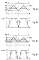
- FIG. 2a shows the time course of the triangular voltage at the time a commutation pulse from a separate circuit position detection of the rotor comes.
- a capacitor across a power source is charged.
- Uh the capacitor is discharged via a second power source.
- the voltage Ul depends on the value of the capacitor and the Charge and discharge currents of the current sources, which are preferred are constant current sources whose currents are proportional to the Increase the engine speed. Move back when the engine speed increases the commutation pulses closer to one another in time, as a result of which the temporal course takes the form of pointed triangles. Since it is the Current sources are constant current sources, however, is an ideal Triangular shape with practically constant differential voltage Uh - Ul vor, which is however proportional to the frequency.
- Fig. 2b shows the result of the voltage curve over time by the Differential amplifier 4 amplified differential signal. That to the inputs of the Differential amplifier 4 applied differential signal consists on the one hand the triangle signal and the other from that in the sample and hold circuit 2 generated withstand voltage Ul. If the gain is chosen like this becomes that at the differential voltage U2 - Ul the amplifier its upper Reached, the curve marked with 3 results in Fig. 2b. The upper limit is marked in the diagram by U Stell. So only the area between line 2 and Ul will open this maximum voltage U Stell amplified. A smaller gain results an output signal with flatter edges, characterized by the Curve course 4. By changing the gain, the method thus enables adjust the slope of the flanks over a wide range.
- Fig. 3a again shows the temporal course of the already shown in Fig. 2a Delta voltage in connection with the commutation pulses.
- Fig. 3a together with Fig. 3b show how drive signals with reduced Block length can be generated. If you add one to the voltage Ul add further voltage U block in the adder 3 and form the difference signal between the triangular signal and this sum voltage Ul + U Block, this is the part of the triangular voltage that is effectively amplified cut off from below in the diagram, resulting in a reduced overall block length.
- the process of forming signals with a shortened block length is now described in more detail.
- the lower of the two lines 5 is the total voltage UI + U block. If the gain is chosen so that the differential voltage U5 - (U1 + U Block) the operational amplifier its control limit U Stell reached, there is an output signal that the curve 8 corresponds.
- the lower of the lines 6 leads in an analogous manner to that Curve shape 7. It is thus possible to use the block voltage U Block To change the block length.
- the circuit according to the invention and the method according to the invention can thus easily increase the slope by varying the gain of a differential amplifier 4 and regardless of Adding a block voltage U block in an adder 3 the block length can be set.
Landscapes
- Engineering & Computer Science (AREA)
- Power Engineering (AREA)
- Control Of Motors That Do Not Use Commutators (AREA)
Description
- Fig. 1
- ein Blockschaltbild eines Ausführungsbeispiels der erfindungsgemäßen Schaltung zur Bereitstellung von Ansteuerungssignalen,
- Fig. 2a
- den zeitlichen Verlauf der Dreiecksspannung,
- Fig. 2b
- den zeitlichen Verlauf der Ansteuerungsimpulse bei voller Blocklänge und veränderbarer Flankensteilheit,
- Fig. 3a
- ebenfalls den zeitlichen Verlauf der Dreiecksspannung, und
- Fig. 3b
- den zeitlichen Verlauf der Ansteuerungsimpulse mit verringer ter Blocklänge.
Claims (10)
- Schaltung zur Ansteuerung eines bürstenlosen Gleichstrommotors mit einem Dreiecksoszillator (1) zur Erzeugung einer Dreiecksspannung in Abhängigkeit von Kommutierungsimpulsen, die sich aus der Position des Rotors des Gleichstrommotors ergeben, dadurch gekennzeichnet, daß ein Abtast-Halteschaltkreis (2) zur Abtastung und zum Halten einer Haltespannung (Ul) aus dem zeitlichen Verlauf der Dreiecksspannung zum Zeitpunkt der Kommutierung und ein Differenzverstärker (4) zum Verstärken der Differenzspannung zwischen der Dreiecksspannung und der Haltespannung (Ul) vorgesehen sind, wobei das Ausgangssignal des Differenzverstärkers der Endstufe der Ansteuerung zugeführt wird.
- Schaltung nach Anspruch 1, gekennzeichnet durch einen zusätzlichen Addierer (3) zum Addieren einer Spannung (U Block) zu der aus der Dreiecksspannung abgetasteten und gehaltenen Haltespannung (Ul), wobei in dem Differenzverstärker (4) die Differenzspannung zwischen der Dreiecksspannung und der Summe aus Haltespannung (Ul) und Blockspannung (U Block) verstärkt wird.
- Schaltung nach Anspruch 1 oder 2, dadurch gekennzeichnet, daß die obere Stellgrenze (U Stell) des Differenzverstärkers (4) auf einen Wert eingestellt werden kann, der niedriger ist als der maximale verstärkte Wert der Differenzspannung.
- Schaltung nach Anspruch 2 oder 3, dadurch gekennzeichnet, daß der Wert der addierten Blockspannung zwischen Null und dem maximalen Wert der Dreiecksspannung liegt.
- Schaltung nach einem der vorhergehenden Ansprüche, dadurch gekennzeichnet, daß die Verstärkung des Differenzverstärkers (4) einstellbar ist.
- Schaltung nach einem der vorhergehenden Ansprüche, dadurch gekennzeichnet, daß der Dreiecksoszillator (1) einen Kondensator, eine erste Stromquelle zur Aufladung des Kondensators und eine zweite Stromquelle zur Entladung des Kondensators aufweist.
- Schaltung nach Anspruch 6, dadurch gekennzeichnet, daß die erste und die zweite Stromquelle Konstantstromquellen sind.
- Schaltung nach Anspruch 6, dadurch gekennzeichnet, daß die Ströme der Konstantstromquellen proportional zu der Drehzahl des Rotors sind.
- Verfahren zum Ansteuern eines bürstenlosen Gleichstrommotors mit einer periodischen Spannung, deren zeitlicher Verlauf durch Spannungsblöcke bestimmter Länge gebildet ist, die steigende und abfallende Flanken haben, dadurch gekennzeichnet, daß die Steilheit der Flanken durch Variieren der Verstärkung eines Differenzverstärkers (4) eingestellt wird.
- Verfahren nach Anspruch 9, dadurch gekennzeichnet, daß die obere Stellgrenze (U Stell) des Differenzverstärkers (4) auf einen Wert eingestellt wird, der niedriger ist als der maximale verstärkte Wert der an den Differenzverstärker (4) angelegten, zu verstärkenden Differenzspannung.
Applications Claiming Priority (3)
| Application Number | Priority Date | Filing Date | Title |
|---|---|---|---|
| DE4432530 | 1994-09-13 | ||
| DE4432530A DE4432530A1 (de) | 1994-09-13 | 1994-09-13 | Schaltung und Verfahren für die Ansteuerung eines bürstenlosen Gleichstrommotors |
| PCT/DE1995/001106 WO1996008864A1 (de) | 1994-09-13 | 1995-08-22 | Schaltung und verfahren für die ansteuerung eines bürstenlosen gleichstrommotors |
Publications (2)
| Publication Number | Publication Date |
|---|---|
| EP0781466A1 EP0781466A1 (de) | 1997-07-02 |
| EP0781466B1 true EP0781466B1 (de) | 1999-04-21 |
Family
ID=6528071
Family Applications (1)
| Application Number | Title | Priority Date | Filing Date |
|---|---|---|---|
| EP95928957A Expired - Lifetime EP0781466B1 (de) | 1994-09-13 | 1995-08-22 | Schaltung und verfahren für die ansteuerung eines bürstenlosen gleichstrommotors |
Country Status (4)
| Country | Link |
|---|---|
| US (1) | US5767641A (de) |
| EP (1) | EP0781466B1 (de) |
| DE (2) | DE4432530A1 (de) |
| WO (1) | WO1996008864A1 (de) |
Families Citing this family (8)
| Publication number | Priority date | Publication date | Assignee | Title |
|---|---|---|---|---|
| DE19719823A1 (de) * | 1997-05-13 | 1998-11-19 | Wolfgang Dr Amrhein | Geräusch- und verlustarme Ansteuerung von bürstenlosen Synchronmotoren |
| DE19756791A1 (de) * | 1997-12-19 | 1999-06-24 | Thomson Brandt Gmbh | Verfahren und Schaltungsanordnung zur Kommutierung eines mehrsträngigen elektrischen Motors |
| US6008611A (en) * | 1998-11-20 | 1999-12-28 | Texas Instruments Incorporated | Method and system for driving a three-phase motor in a mass storage device |
| DE19951364A1 (de) * | 1999-10-26 | 2001-05-10 | Bosch Gmbh Robert | Elektronisch kommutierbarer Motor |
| US6538403B2 (en) | 2000-01-07 | 2003-03-25 | Black & Decker Inc. | Brushless DC motor sensor control system and method |
| US6975050B2 (en) | 2000-01-07 | 2005-12-13 | Black & Decker Inc. | Brushless DC motor |
| WO2001052384A1 (en) | 2000-01-07 | 2001-07-19 | Black & Decker Inc. | Brushless dc motor |
| DE10150448A1 (de) * | 2001-10-12 | 2003-04-30 | Conti Temic Microelectronic | Verfahren zur Steuerung eines elektronisch kommutierten Motors |
Citations (1)
| Publication number | Priority date | Publication date | Assignee | Title |
|---|---|---|---|---|
| EP0482913A2 (de) * | 1990-10-25 | 1992-04-29 | Matsushita Electric Industrial Co., Ltd. | Bürstenloser, sensorloser Motor |
Family Cites Families (14)
| Publication number | Priority date | Publication date | Assignee | Title |
|---|---|---|---|---|
| US3710216A (en) * | 1971-04-06 | 1973-01-09 | Eaton Corp | Scr motor speed control with plug sensing circuit |
| US3999108A (en) * | 1972-08-16 | 1976-12-21 | Canon Kabushiki Kaisha | Speed regulation system for DC motors with hall generators |
| US4356437A (en) * | 1979-07-20 | 1982-10-26 | Hitachi, Ltd. | Control circuit for DC motors |
| CH652226A5 (de) * | 1980-04-16 | 1985-10-31 | Papst Motoren Kg | Drehzahlregelanordnung. |
| NL8301714A (nl) * | 1983-05-13 | 1984-12-03 | Philips Nv | Driehoekgenerator. |
| US4641066A (en) * | 1984-10-04 | 1987-02-03 | Nippondenso Co., Ltd. | Control apparatus for brushless motor |
| IE851629L (en) * | 1985-06-28 | 1986-12-28 | Kollmorgen Ireland Ltd | Electrical drive systems |
| DE3546891C2 (de) * | 1985-10-21 | 2000-06-08 | Papst Licensing Gmbh & Co Kg | Treiberschaltung zum Betrieb eines kollektorlosen Gleichstrommotors in einem Lüfter oder zum Antrieb eines Lüfters |
| DE3891000C2 (de) * | 1987-11-20 | 1991-11-21 | Matsushita Electric Industrial Co., Ltd., Kadoma, Osaka, Jp | |
| JP2563523B2 (ja) * | 1988-10-07 | 1996-12-11 | 松下電器産業株式会社 | ブラシレスモータの駆動装置 |
| DE4019338A1 (de) * | 1990-06-18 | 1991-12-19 | Papst Motoren Gmbh & Co Kg | Treiberschaltung fuer einen buerstenlosen gleichstrommotor |
| US5220258A (en) * | 1990-06-18 | 1993-06-15 | Papst-Motoren Gmbh & Co. Kg | Drive circuit for a brushless direct-current motor |
| US5319290A (en) * | 1992-01-10 | 1994-06-07 | Rohm Co., Ltd. | Motor control circuit and motor drive system using the same |
| DE4204351C2 (de) * | 1992-02-14 | 2003-06-18 | Bosch Gmbh Robert | Schaltungsanordnung zum Betreiben eines Mehrphasen-Synchronmotors an einem Gleichspannungsnetz |
-
1994
- 1994-09-13 DE DE4432530A patent/DE4432530A1/de not_active Ceased
-
1995
- 1995-08-22 WO PCT/DE1995/001106 patent/WO1996008864A1/de not_active Ceased
- 1995-08-22 EP EP95928957A patent/EP0781466B1/de not_active Expired - Lifetime
- 1995-08-22 DE DE59505721T patent/DE59505721D1/de not_active Expired - Lifetime
- 1995-08-22 US US08/793,517 patent/US5767641A/en not_active Expired - Lifetime
Patent Citations (1)
| Publication number | Priority date | Publication date | Assignee | Title |
|---|---|---|---|---|
| EP0482913A2 (de) * | 1990-10-25 | 1992-04-29 | Matsushita Electric Industrial Co., Ltd. | Bürstenloser, sensorloser Motor |
Also Published As
| Publication number | Publication date |
|---|---|
| WO1996008864A1 (de) | 1996-03-21 |
| US5767641A (en) | 1998-06-16 |
| DE59505721D1 (de) | 1999-05-27 |
| DE4432530A1 (de) | 1996-03-14 |
| EP0781466A1 (de) | 1997-07-02 |
Similar Documents
| Publication | Publication Date | Title |
|---|---|---|
| EP0242387B1 (de) | Kollektorloser gleichstrommotor, treiberschaltung für einen kollektorlosen gleichstrommotor sowie verfahren zum betrieb eines kollektorlosen gleichstrommotors | |
| DE3934139C2 (de) | Elektronische Steuerschaltung für einen bürstenlosen Gleichstrommotor | |
| DE3686722T2 (de) | Buerstenfreier gleichstrommotor. | |
| DE69822896T2 (de) | Verfahren und gerät zur steuerung eines bürstenlosen elektrischen motors | |
| DE2403432A1 (de) | Gleichstrommotor mit mehrphasiger staenderwicklung und durch hallgeneratoren gesteuerter elektronischer kommutierungseinrichtung | |
| DE3838579C2 (de) | ||
| DE19860446A1 (de) | Verfahren zur Regelung eines spannungs-/frequenzumrichtergesteuerten Mehrphasen-Permanentmagnetmotors | |
| DE2629927C2 (de) | Anordnung zur Drehzahlregelung eines Synchronmotors | |
| DE2251292C3 (de) | Anordnung zur Drehzahlregelung eines kollektorlosen Gleichstrommotors | |
| DE69705754T2 (de) | Elektrische Servolenkung | |
| EP0470672B1 (de) | Schaltungsanordnung zum Kommutieren eines Reluktanzmotors | |
| WO2004091088A1 (de) | Schaltungsanordnung und verfahren zur ansteuerung eines bürstenlosen permanenterregten gleichstrommotors | |
| DE3819064C3 (de) | Verfahren zur Steuerung von bürstenlosen Elektromotoren sowie Steuerschaltung hierfür | |
| EP0007552A1 (de) | Schaltungsanordnung zur Bildung eines elektrischen Spannungssignals, das einer Flusskomponente in einer Drehfeldmaschine proportional ist | |
| DE69302431T2 (de) | Schnittstellenschaltung zur Erzeugung eines analogen Signals um die Drehgeschwindigkeit eines elektrischen Gleichstrommotors, insbesondere eines bürstenlosen Motors, zu regeln | |
| DE3940569A1 (de) | Schaltungsanordnung zum betreiben eines mehrphasen-synchronmotors an einem gleichspannungsnetz | |
| EP0781466A1 (de) | Schaltung und verfahren für die ansteuerung eines bürstenlosen gleichstrommotors | |
| DE3036908A1 (de) | Kollektorloser elektronikmotor | |
| DE69206503T2 (de) | Hochgeschwindigkeits-gleichstrommotor. | |
| EP1070382B1 (de) | Drehzahl-steuervorrichtung für einen elektronisch kommutierten mehrphasigen elektromotor | |
| EP0190240B1 (de) | Kollektorloser gleichstrommotor | |
| DE69827592T2 (de) | Verfahren und Schaltungsvorrichtung zur Kommutation eines elektrischen Motors mit mehreren Windungen | |
| DE2754241A1 (de) | Statischer frequenzumformer nach dem gleichstrom-zwischenkreis-prinzip zur speisung von drehstrommotoren | |
| WO2004004111A1 (de) | Mehrphasiger kollektorloser gleichstrommotor | |
| DE29516307U1 (de) | Anordnung zur Erzeugung eines Drehzahl-Istwertsignals |
Legal Events
| Date | Code | Title | Description |
|---|---|---|---|
| PUAI | Public reference made under article 153(3) epc to a published international application that has entered the european phase |
Free format text: ORIGINAL CODE: 0009012 |
|
| AK | Designated contracting states |
Kind code of ref document: A1 Designated state(s): DE FR GB IT |
|
| 17P | Request for examination filed |
Effective date: 19970414 |
|
| 17Q | First examination report despatched |
Effective date: 19970821 |
|
| GRAG | Despatch of communication of intention to grant |
Free format text: ORIGINAL CODE: EPIDOS AGRA |
|
| GRAG | Despatch of communication of intention to grant |
Free format text: ORIGINAL CODE: EPIDOS AGRA |
|
| GRAH | Despatch of communication of intention to grant a patent |
Free format text: ORIGINAL CODE: EPIDOS IGRA |
|
| GRAH | Despatch of communication of intention to grant a patent |
Free format text: ORIGINAL CODE: EPIDOS IGRA |
|
| GRAA | (expected) grant |
Free format text: ORIGINAL CODE: 0009210 |
|
| AK | Designated contracting states |
Kind code of ref document: B1 Designated state(s): DE FR GB IT |
|
| REF | Corresponds to: |
Ref document number: 59505721 Country of ref document: DE Date of ref document: 19990527 |
|
| GBT | Gb: translation of ep patent filed (gb section 77(6)(a)/1977) |
Effective date: 19990616 |
|
| ET | Fr: translation filed | ||
| PLBE | No opposition filed within time limit |
Free format text: ORIGINAL CODE: 0009261 |
|
| STAA | Information on the status of an ep patent application or granted ep patent |
Free format text: STATUS: NO OPPOSITION FILED WITHIN TIME LIMIT |
|
| 26N | No opposition filed | ||
| REG | Reference to a national code |
Ref country code: GB Ref legal event code: IF02 |
|
| PGFP | Annual fee paid to national office [announced via postgrant information from national office to epo] |
Ref country code: GB Payment date: 20090821 Year of fee payment: 15 |
|
| PGFP | Annual fee paid to national office [announced via postgrant information from national office to epo] |
Ref country code: IT Payment date: 20090824 Year of fee payment: 15 |
|
| PGFP | Annual fee paid to national office [announced via postgrant information from national office to epo] |
Ref country code: FR Payment date: 20100901 Year of fee payment: 16 |
|
| PGFP | Annual fee paid to national office [announced via postgrant information from national office to epo] |
Ref country code: DE Payment date: 20101025 Year of fee payment: 16 |
|
| GBPC | Gb: european patent ceased through non-payment of renewal fee |
Effective date: 20100822 |
|
| PG25 | Lapsed in a contracting state [announced via postgrant information from national office to epo] |
Ref country code: IT Free format text: LAPSE BECAUSE OF NON-PAYMENT OF DUE FEES Effective date: 20100822 |
|
| PG25 | Lapsed in a contracting state [announced via postgrant information from national office to epo] |
Ref country code: GB Free format text: LAPSE BECAUSE OF NON-PAYMENT OF DUE FEES Effective date: 20100822 |
|
| REG | Reference to a national code |
Ref country code: FR Ref legal event code: ST Effective date: 20120430 |
|
| PG25 | Lapsed in a contracting state [announced via postgrant information from national office to epo] |
Ref country code: FR Free format text: LAPSE BECAUSE OF NON-PAYMENT OF DUE FEES Effective date: 20110831 |
|
| PG25 | Lapsed in a contracting state [announced via postgrant information from national office to epo] |
Ref country code: DE Free format text: LAPSE BECAUSE OF NON-PAYMENT OF DUE FEES Effective date: 20130301 |
|
| REG | Reference to a national code |
Ref country code: DE Ref legal event code: R119 Ref document number: 59505721 Country of ref document: DE Effective date: 20130301 |