EP0780994A2 - Schaltung zur Umschaltung des Speiseweges - Google Patents
Schaltung zur Umschaltung des Speiseweges Download PDFInfo
- Publication number
- EP0780994A2 EP0780994A2 EP96402828A EP96402828A EP0780994A2 EP 0780994 A2 EP0780994 A2 EP 0780994A2 EP 96402828 A EP96402828 A EP 96402828A EP 96402828 A EP96402828 A EP 96402828A EP 0780994 A2 EP0780994 A2 EP 0780994A2
- Authority
- EP
- European Patent Office
- Prior art keywords
- relay
- terminal
- feeding
- grounded
- activated
- Prior art date
- Legal status (The legal status is an assumption and is not a legal conclusion. Google has not performed a legal analysis and makes no representation as to the accuracy of the status listed.)
- Granted
Links
Images


Classifications
-
- H—ELECTRICITY
- H04—ELECTRIC COMMUNICATION TECHNIQUE
- H04B—TRANSMISSION
- H04B3/00—Line transmission systems
- H04B3/02—Details
- H04B3/44—Arrangements for feeding power to a repeater along the transmission line
Definitions
- the present invention relates to a feeding pass switching circuit for switching feeding passes with respect to repeaters or branching units installed on a transmission network in a long distance optical transmission system such as a submarine optical cable transmission system.
- a submarine optical cable system can perform a long distance digital transmission having a large capacity owing to a transmission loss factor or wideband property of an optical fiber, especially, a plurality of optical fiber pairs can be accommodated in submarine optical cables, leading to an advantage that the optical fiber pairs are branched per unit in the sea, thereby connecting a plurality of land stations. Accordingly, the submarine optical cable system can achieve a multi-point structure connecting three or more terminal stations (hereinafter referred to as land stations) regardless of a point-to-point structure.
- land stations terminal stations
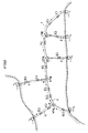
- T1 to T6 land stations installed on the land.
- 1 to 5 are submarine optical cables for connecting between each of the land stations T1 to T6.
- C1 to C13 are optical repeaters which are respectively inserted into the submarine optical cables 1 to 5 at an interval of, e.g., about 10 Km
- BU1 to BU4 are branching units for branching signals transmitted in one submarine optical cable into a plurality of optical cables in this case.
- a main submarine optical cable 1 is installed between the land stations T1 and T4 in this example, and the submarine optical cables 2 to 5 are respectively branched from the branching units BU1 to BU4 which are inserted into the submarine optical cable 1 with respects to the other land stations T2 to T6. With such an arrangement, the transmission between each land station is performed.
- Power must be fed from power feeding units of the land stations T1 to T6 to the optical repeaters C1 to C 13 and the branching units BU1 to BU4 of the submarine optical cable system having such an arrangement.
- the power is supplied or fed utilizing copper tubes of the submarine optical cable or high tensile strength piano wires.
- the power feeding or feeding system adopts a one time terminal feeding system (hereinafter referred to as one terminal feeding system) for feeding the power from one power feeding unit of one land station alone and a both terminal feeding system (hereinafter referred to as both terminal feeding system) for feeding the power from the power feeding units of two land stations, wherein two terminal feeding system is normally adopted for a long distance transmission.
- FIG. 4 shows one example of such a feeding pass.
- the power is fed to the optical repeater C1, C2, C4, C6, C9, C10, C13 and the branching units BU1 to BU4 respectively provided in the submarine optical cable 1 connecting between the land stations T1 and T4 by way of the both terminal power feeding system having the positive electrode at the land station T1 and the negative electrode at the land station T4.
- the submarine optical cable 2 is grounded to sea water by way of an electrode provided in a casing of the branching unit BU1, and the power supply voltage (hereinafter referred to as feeding voltage) having the negative electrode is supplied to the circuit from the land station T2 so that the power is fed from the land station T2 to the optical repeater C3 inserted into the submarine optical cable 2 by way of the one terminal feeding system.
- the power is also fed to the submarine optical cable 3 between the branching unit BU2 and the land station T3, the submarine optical cable 4 between the branching unit BU3 and the land station T5, and the submarine optical cable 5 between the branching unit BU4 and the land stations T6 by way of the one terminal feeding system from the land stations.
- the reason that electrode is grounded to sea water is to prevent the electrode per se from being broken down due to electrolytic reaction to be corroded.
- feeding pass switching circuits for switching the feeding pass in each of the branching units BU1 to BU4 for ensuring a transmission pass using other submarine optical cables in case that one of submarine optical cables is troubled. Since the branching units BUs are installed in the seabed, the feeding pass switching circuit is realized by elements having high reliability such as vacuum relays activable by the power supply current (hereinafter feeding current).
- Fig. 5 shows an example of such a feeding pass switching circuit, wherein denoted by A, B and C are respectively terminals to which optical cables are connected, and the optical cables are connected to power feeding units of the land stations by way of optical repeaters.
- Denoted by E is a ground terminal connected to sea water as mentioned above.
- K1 and K2 are relays for use in high voltage such as vacuum relays, k1 and k2 are respectively contacts of the relays K1 and K2. Each contact of the relays is connected to "1" in its initialize state, and it can be switched to "2" when the relays are activated.
- a land station connected to the terminal A is first grounded, and a land station connected to the terminal C is put in an open circuit Further, the negative feed voltage is applied to the system from the land station connected to the terminal B. Thereafter, there is supplied a power supply current (hereinafter referred to as feeding current) in proportion to the feed voltage to the relay K1 when the feed voltage is gradually increased, and the contact k1 is switched to "2" when this current exceeds a sensitive current of the relay K1 so that the terminal C is grounded to sea water by way of the terminal E. Successively the positive feed voltage is applied to the system from the land station connected to the terminal A.
- feeding current a power supply current
- the cable connected to the terminal A and the cable connected to terminal B are subject to the both terminal feeding system from the land stations connected to the terminals A and B. Further, in the state when the negative feed voltage is applied to the circuit from the land station connected to the terminal C, the feed current from the ground to the terminal C by way of the relay K1 so that the power is fed from the land station connected to the terminal C to the cable connected to the terminal C by way of the one terminal feeding system. In such a manner, the feeding system can be controled depending on a manner of application of the voltage when the system is started up.
- the potentials of the terminals C and B, and the contact k1 in the vicinity thereof become substantially 0 [V], but the potentials of the terminals A and B and the relay K2 in the vicinity thereof become values other than 0 [V] in case of the both terminal feeding system condition where the power is fed from the terminals A and B and the one terminal feeding system condition where the power is fed from the terminal E to the terminal C. Accordingly, when the feed current does not flow owing to the malfunction or at the terminal A or terminal B , the contact k1 is restored to the "1" but an arc discharge current is generated in the contact k1, thereby generating the contact trouble. Accordingly, there is proposed a feeding pass switching circuit for preventing the system from being switched in such a high voltage application states (see JP-A 63/189025)
- a feeding pass switching circuit comprises first, second and third terminals respectively connected to a feeding pass, a first relay having one end connected to the first terminal, the first relay activable by a current flowing thereto from the first terminal, a second relay connected between the second terminal and a first diode connected to another end of the first terminal, the second relay being activable by a current flowing in the same direction as that flowing to the first relay, a third relay connected to the second terminal, the this relay being activable by a current flowing to either direction, a forth relay connected between the third terminal and a second diode connected to the another end of the first relay, the forth relay being activable only by a current flowing in the same direction as that flowing to the first relay and having a sensitivity lower than that of the first relay, a fifth relay connected between the third terminal and the third relay, the fifth relay being activable by the current flowing to either direction and having a sensitively lower than that of the third relay, wherein the third relay is disconnected from the fifth relay when the
- a feeding pass switching circuit comprises first, second and third terminals respectively connected to a feeding pass, a first relay connected between a first diode connected to the first terminal and the second terminal, the first relay activable only by a current flowing to the second terminal and having a sensitivity lower than that of the second relay, a second relay connected to the second terminal, the second relay being activable by a current flowing to either direction, a third relay connected between a second diode connected to the first terminal and the third terminal, the third relay being activable only by a current flowing to the third terminal and having a sensitivity lower than that of the second relay, a forth relay connected between the third terminal and the second relay, the forth relay being activable by a current flowing to either direction and having a sensitivity lower than that of the first relay, wherein the third relay is disconnected from the feeding pass switching circuit when the first relay is activated, a connection point between the second relay and fourth relay is grounded, and the first terminal is separated form the feeding pass switching circuit and grounded when the second relay is activated,
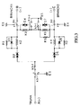
- Fig. 1 shows a feeding pass switching circuit according to a first embodiment of the present invention.
- A, B and C are respectively terminals of the feeding pass switching circuit to which submarine optical cables are respectively connected.
- the optical cable connected to the terminal A is a TRUNK
- the optical cable connected to the terminal B is a BRANCH1
- the optical cable connected to the terminal C is a BRANCH2.
- K1 to K5 are first to fifth relays comprising vacuum relays, etc.
- k1, k2, k3-1, k3-2, k4, k5-1 and k5-2 are respectively contacts of these relays K1 to K5.
- the contacts of these relay K1 to K5 are in the state as illustrated in Fig.
- D1 to D7 are zener diodes
- R1 to R3 are resistors
- E1 to E5 are ground terminals connected to sea water by way of a housing of the feeding pass switching circuit.
- the reason that the zener diodes D1, D3 and D 6 are connected in parallel with the relays K1, K2 and K4 is that the voltage to be applied to both ends of the relays K1, K2 and K4 is limited when the current flows from the terminal A to the terminal B or C , and the relays K1, K2 and K4 are not activated by a current flowing in the opposite direction, namely, from the terminal B or C to the terminal A.
- the reason that the zener diodes D4 and D7 are connected in parallel with the relays K3 and K5 are respectively connected in series with each other in an opposite direction in the polarity thereof is that the relays K3 and K5 can be activated even if the current flows in either direction and the voltage to be applied to both ends thereof is limited.
- resistors R1, R2 and R3 are connected in parallel with the relays K2, K4 and K5 is that a current flowing to the relays is divided to lower each sensitivity of the relays K2, K4 and K5 than that of the relays K1 and K3.
- the resistance values of these resistors R1, R2 and R3 are substantially the same as the resistance value of the windings of the relays.
- the zener diodes in Fig. 1 respectively have the same zener voltage which is slightly greater than an operation voltage of the relays K1 to K5.
- the zener diodes D2 and D5 comprise a plurality of diodes which are connected in series to one another, it is not necessary that they may comprise a plurality of diodes connected in series to one another or they may comprise ordinary diodes if they can obtain desired zener voltages.
- the terminal C (BRANCH2) in the land station connected to the terminal C is first put in an open circuit, and the terminal A (TRUNK) in the land station connected to the terminal A is grounded.
- a negative voltage is gradually applied from the land station connected to the terminal B (BRANCH 1).
- the current starts to flow from the grounded terminal A (TRUNK) to the terminal B (BRANCH1) by way of two current passes, i.e., a first current pass through which the current flows in the order of the relays K1 and K2 and another current pass through which the current flows from the relay K1 to the relays K4, K5 and K3.
- a first current pass through which the current flows in the order of the relays K1 and K2 and another current pass through which the current flows from the relay K1 to the relays K4, K5 and K3.
- the relays K4, K5 and K3 are connected in series with one another, the current flowing through the relays K4, K5 and K3 becomes smaller than that flowing through the relay K2.
- the relay K1 is activated first, so that the contact k1 thereof is put in an open circuit As a result, the current path through which the current flows to the relay K3 is put in an open circuit Since at this time the resistance value of the circuit becomes high, the current flowing through the relay K1 is reduced instantaneously so that the relay K1 must have hysteresis property to prevent the relay K1 from being again in an inactivable state.
- the relay K2 is activated after the relay K1 is activated.
- the contact k2 is switched so that the terminal C (BRANCH2) is connected to the terminal E4 so as to be grounded to sea water.
- the circuit is in two feeding systems, namely, the both terminal feeding system where the power is fed from the terminal A (TRUNK) and the terminal B (BRANCH 1) and the one terminal feeding system where the power is fed from the terminal C (BRANCH2).
- the terminal B (BRANCH1) is first open to feed the negative current from the terminal C (BRANCH2).
- the circuit in two feeding systems, namely, the both terminal feeding system where the power is fed from the terminal A (TRUNK) and the terminal C (BRANCH2) and the one terminal feeding system where the power is fed from the terminal B (BRANCH 1).
- the terminal A (TRUNK) is put in an open circuit and the terminal C (BRANCH2) is grounded. Thereafter, the positive current is supplied from the terminal B (BRANCH1).
- the current starts to flow by way of two current passes, i.e., a first current pass through which the current flows in the order of the terminal B, the contact k4, the relay K3, the contact k1, the relay K5, the contact k2 and the terminal C, and a second current pass through which the current flows in the order of the terminal B, the contact k4, the diode D3, the diode D2, the diode D5, the relay K4, the contact k2, the terminal C.
- the relay K4 since the zener diode D2, e.g., composed of two zener diodes which are connected in series with each other is interposed on the second current pass through which the current flows the relay K4, a voltage to be applied to the relays K2 and K4 is small so that the current scarcely flows. Since the relay K5 is connected in parallel with the resistor R3, the relay K3 is first activated.
- the contact k3-2 is made conductive, thereby forming a circuit to be grounded to the ground terminal E5 by way of the terminal B, the contact k4, the relay K3 and the contact k3-2, wherein the relay K3 is put in self-holding. Further the contact k3-1 of the relay K3 is also switched to "2", and the terminal A (TRUNK) is connected to the ground terminal El by way of the relay K1, and the TRUNK of the terminal A is separated from the BRANCH1 and the BRANCH2. Further, at this time, since the terminal A (TRUNK) is put in an open circuit, the relay K1 is not activated.
- the negative voltage is applied from the terminal C (BRANCH2) to the system so as to permit the negative current to flow. Accordingly, the current flows through the ground terminal E5, the contact k3-2, the contact k1, the relay K5, the contact k2 and the terminal C so that the relay K5 is activated. As a result, the contact k 5-1 is conducted so that the relay K5 is put in self-holding and the contact k 5-2 is put in an open circuited.
- the relay K3 is instantaneously in an inactivable condition.
- One end of the relay K3 is connected to the ground terminal E5 and it is permitted again to be in an activable condition owing to the negative voltage to be applied from the terminal B since the relay K5 is activated a set forth about
- the terminal B (BRANCH1) and the terminal C (BRANCH2) are respectively grounded at the ground terminal E5, so that the power is fed from he terminal B (BRANCH1) and the terminal C (BRANCH2).
- the positive current is permitted to flow from the terminal A (TRUNK).
- the terminal C (BRANCH2) is first open so as to supply the positive current to satisfy the activation of relays using the constant current source from the terminal B (BRANCH1).
- Most of the current flows to the TRUNK which is grounded to sea water by way of the terminal B, the contact k4, the relay K2, the diode D2, the contact k 5-2, the contact k3-1, the relay K1 and the terminal A, but these relays are not activated since the relays K2 and K1 are respectively connected in parallel with the diodes D3 and D1.
- Part of the current flows to the path formed by the relay K3, the contact k1, the relay K5, the relay K4 and the diode D5, but these relays are not activated since the voltage applied to these relays are controlled by diodes D2, D3 and D5.
- the negative voltage is applied from the land station connected to the BRANCH2 of the terminal C so as to flow the negative current from the terminal C.
- This current flows to the BRANCH1 of the terminal B from the contact k mainly by way of the relays K3 and K5. Since the relay K5 is connected in parallel with the resistor R3 and is low sensitivity, the relay K3 is activated first Accordingly, the contact k3-2 is made conductive, and it is grounded to the ground terminal E5. As a result, the current flows from the BRANCH1 of the terminal B to the relay K3, and the relay K3 is put in self-holding.
- the contact k3-1 is switched to "2"
- the TRUNK of the terminal A is connected to the ground terminal El by way of the relay K1
- the TRUNK is separated from the branching unit
- the relay K5 is activated. Accordingly, the contact k 5-1 is made conductive so that one end of the relay K5 is grounded to the ground terminal E5, and hence the relay K5 is put in self-holding. Further, the TRUNK is made in a double separated condition by the contact k 5-2.
- the TRUNK is separated and the power is fed between the BRANCH1 and the BRANCH2.
- the BRANCH1 When there occurs trouble at the BRANCH2, the BRANCH1 is put in an open circuit when the system is restarted and the positive current flows from the TRUNK of the terminal A. This current flows to the connecting point of the BRANCH2 by way of the pass formed by the terminal A of the relay K1, the contact k3-1, the contact k5, the diode B5, the relay K4, the contact k2 and the terminal C, and another pass formed by the terminal A, the relay K1, the contact k3-1, the contact k 5-2, the diode D2, the relay K2, the relay K3, the contact k1, the relay K5, the contact k2 and the terminal C.
- the relay K1 is activated first Accordingly, the contact k1 is put in an open circuit At this time, although the impedance is temporarily increased so that the current flowing to the relay K1 is reduced temporarily, the relay K1 is used to have hysteresis properties so as to prevent the relay K1 from being in an OFF condition again.
- the current becomes the one flowing to the relay K1 by way of the relay K2, the diode D2, the contact k 5-2 and the contact k3-1 and another one flowing to the relay K2, the diode D2, the diode D5 and the relay K4.
- two currents flowing to the relay K1 have the same phases and two currents flowing to the relay K4. have an inverse phases.
- the potential of the BRANCH1 is gradually decreased, the current flowing to the relay K2 is increased so that the relay K2 is activated.
- the contact k2 is switched to "2", and hence the BRANCH2 is separated from the branching unit to be grounded to the ground terminal E4.
- the feeding pass switching circuit showing Fig. 1 it is possible to form the feeding pass between two terminals, i.e., the TRUNK and either of the BRANCH1 and the BRANCH2.
- the terminal A of the TRUNK of the feeding pass switching circuit in the branching unit BU1 is connected to the land station T1
- the terminal B of the BRANCH1 is connected to the terminal A of the TRUNK of the succeeding branching unit BU2
- the terminal C of the BRANCH2 is connected to the land station T2
- the terminal B of the BRANCH1 of the branching unit BU2 is connected to the terminal A of the TRUNK of the succeeding branching unit BU3
- the terminal C of the BRANCH2 is connected to the land station T3
- the terminal B of the BRANCH1 of the branching unit BU4 is connected to the land station T4.
- the branched land stations T2, T3, T5 and T6 permit the submarine optical cables 2 to 5 connected thereto to be put in an open circuit, and the land station T1 permits the cable to be grounded. As shown in Fig.
- Fig. 3 shows a feeding pass switching circuit according to a second embodiment of the present invention.
- the components which are the same as those in Fig. 1 are denoted by the same numerals and the detailed explanation thereof is omitted.
- the second embodiment reduces the number of components in the first embodiment shown in Fig. 1, by eliminating the relay K1 and the diode D1 connected in parallel with the relay K1. The reduction of the components can enhance reliability and permit the branching unit BU to be miniaturized.
- the terminal C (BRANCH 2) is put in an open circuit at the land station connected to the terminal C, and the terminal A (TRUNK) is grounded at the land station connected to the terminal A. And, a negative voltage is increasingly applied from the terminal connected to terminal B (BRANCH 1). Then, a current starts flowing from the grounded terminal A (TRUNK) to the terminal B (BRANCH 1) through the two paths: one passing the relay K2 and another one passing relay K4, K5, and K3.
- the current flowing through the relay K4, K5, and K3 is smaller than the current flowing through the relay K2 because the relay K4, K5, and K3 are connected in series.
- the windings of the relays each have a resistance R and the resistor R1, R2, and R3 also have the same resistance R
- the resistance of the parallel circuit formed of the relay K2, the zener diode D3, and the resistor R1, the parallel circuit formed of the relay K4, the diode D6, and the resistor R2, and the parallel circuit formed of the relay K5, diode D7, and the resistor R3 all become substantially R/2
- the resistance of the parallel circuit formed of relay K3 and the diode D4 becomes substantially R Therefore, if the value of a current flowing into from the TRUNK is I, a current flowing through the relay K2 will be (2/5) ⁇ I and a current flowing through the relay K3 will be (1/5) ⁇ I. Therefore, the relay k2 is first activated to switch the contact k2, and the BRANCH 2 is separated from the branching unit and is grounded at the terminal E4.
- terminal A terminal A
- terminal B terminal A
- Vz Zener voltage of the Zener diode D3 + 2Vf (forward voltage drop of the diode D2) due to the diode D2 and the Zener diode D3 connected in parallel to the relay K2. Since the voltage drop by the diode D5 is 2Vf, each of relay K4, K5, and K3 is applied the a voltage such that Zener voltage Vz is divided in correspondence with the impedance of each of the relays.
- the voltages applied to relay K4 and K5 are Vz/4 each and the voltage applied to the relay K3 is Vz/2. Therefore, using a relay that is not activated in its characteristics at half of the Zener voltage Vz of the Zener diode D3 will not activate these relays. Thus, feeding TRUNK and BRANCH1 can be done.
- the BRANCH 1 is put in an open circuit, the TRUNK is grounded, a negative current is supplied from the BRANCH 2, and afterward, a positive current is supplied from the TRUNK, so that the power is fed to the TRUNK and BRANCH 2 in the same manner as the above.
- the TRUNK is put in an open circuit and BRANCH 2 is grounded, and in this state a positive current is gradually supplied from the BRANCH 1, and then a current flowing into from the BRANCH 1 runs through a path formed of the relay K3 and K5. Since the sensitivity of the relay K5 is decreased by the resistor R3, relay K3 is activated and the contact k3-2 is grounded to the E5. Thereby, the current flowing through the relay K3 is increased to put the relay K3 in self-holding. And, the contact k3-1 is switched to the "2" and the TRUNK is grounded at the ground terminal E1.
- feeding a negative current from the BRANCH 2 will flow a current through the contact k3-2, the relay K5, and the contact k2 from the ground terminal E5 to activate the relay K5.
- the contact k5-1 is made conductive to be doubly grounded at the ground terminal E5.
- the TRUNK is doubly separated by the contact k5-2.
- the BRANCH 1, or the BRUNCH 2 applying any one of the procedures of the foregoing start-up procedure in normal operation that is suited to the state of the present trouble to restart can reform a feeding path.
- BRANCH 1 If there occurs a shunt trouble at the BRUNCH 2, BRANCH 1 is put in an open circuit at restarting, a constant positive current is supplied from the TRUNK. If a relay activating current is Ic, a current of, for example, 21c is applied. The current flows through the terminal A and the contact k3-1 and the k5-2 via a path passing the Zener diode D5 and the relay K4, and another path passing the Zener diode D2, the relay K2, the relay K3, and the relay K5 to the contact k2 and the terminal C, which is grounded to the sea from the BRANCH 2 having a shunt trouble. The current flowing through the former and latter path are (8/5) ⁇ Ic and (2/5) ⁇ Ic, respectively. Here, none of relays are activated.
- feeding a negative current from the BRANCH 1 of the terminal B makes tow current paths: one passing the relay K4, the diode D5, the diode D2, and the relay K2; another one passing the relay K5 and the relay K3.
- the two currents flowing through the relay K2 are in phase, however, the two currents flowing through relay K4, relay K3, and relay K5 are in the reverse phase; and increasingly feeding a positive current from the BRANCH 1 can activate the relay K2.
- the current applied at the terminal B is (8/3) ⁇ Ic
- the current flowing through relay K2 will be Ic
- current flowing through relay K4 will be 0
- a current flowing through the relay K3 will be (2/3) ⁇ Ic
- a current flowing through the relay K5 will be (1/3) ⁇ Ic; and only the relay K2 will be activated.
- restarting will be performed by replacing BRANCH 2 with the BRANCH 1 in the procedure of the shunt trouble of the BRANCH 2 described above; thus forming a feeding path from the TRUNK to the BRANCH 2.
- resistor R1 ⁇ R3 are made identical to the resistance of coils of the relays, however, it can be set to the other value. And, interposing a resistor in parallel to the relay K3 can change the value of current at restarting in the shunt trouble of the BRANCH.
Landscapes
- Engineering & Computer Science (AREA)
- Computer Networks & Wireless Communication (AREA)
- Signal Processing (AREA)
- Cable Transmission Systems, Equalization Of Radio And Reduction Of Echo (AREA)
- Optical Communication System (AREA)
Applications Claiming Priority (3)
| Application Number | Priority Date | Filing Date | Title |
|---|---|---|---|
| JP349043/95 | 1995-12-21 | ||
| JP34904395 | 1995-12-21 | ||
| JP34904395A JP3341245B2 (ja) | 1995-12-21 | 1995-12-21 | 給電路切替回路 |
Publications (3)
| Publication Number | Publication Date |
|---|---|
| EP0780994A2 true EP0780994A2 (de) | 1997-06-25 |
| EP0780994A3 EP0780994A3 (de) | 1999-08-18 |
| EP0780994B1 EP0780994B1 (de) | 2002-09-25 |
Family
ID=18401111
Family Applications (1)
| Application Number | Title | Priority Date | Filing Date |
|---|---|---|---|
| EP19960402828 Expired - Lifetime EP0780994B1 (de) | 1995-12-21 | 1996-12-19 | Schaltung zur Umschaltung des Speiseweges |
Country Status (3)
| Country | Link |
|---|---|
| US (1) | US5790358A (de) |
| EP (1) | EP0780994B1 (de) |
| JP (1) | JP3341245B2 (de) |
Cited By (4)
| Publication number | Priority date | Publication date | Assignee | Title |
|---|---|---|---|---|
| EP1322046A1 (de) * | 2001-12-19 | 2003-06-25 | PIRELLI S.p.A. | Unterseeverzweigungseinheit mit asymmetrischer Struktur |
| EP0935348A3 (de) * | 1998-02-09 | 2003-11-26 | Nec Corporation | Kabelverzweigungseinheit |
| US7067940B2 (en) | 2001-12-19 | 2006-06-27 | Pirelli Cavi E Sistemi S.P.A. | Submarine branching unit having asymmetrical architecture |
| US7269353B2 (en) | 2001-09-10 | 2007-09-11 | Alcatel | Branching unit for an optical transmission system |
Families Citing this family (8)
| Publication number | Priority date | Publication date | Assignee | Title |
|---|---|---|---|---|
| DE19939650C2 (de) * | 1999-08-13 | 2001-08-02 | Siemens Ag | Schaltungsanordnung zum Betrieb eines Relais |
| JP3759704B2 (ja) * | 2001-07-18 | 2006-03-29 | 三菱電機株式会社 | 給電路切替回路および海中分岐装置 |
| EP2574968B1 (de) * | 2011-09-29 | 2019-04-10 | Alcatel Lucent | Unterwasserverbindungseinrichtung mit Erdungseinheit |
| CN103066830B (zh) * | 2012-11-14 | 2015-04-08 | 航宇救生装备有限公司 | 通用海水激活电路 |
| CN103701493B (zh) * | 2013-10-16 | 2016-04-06 | 中国电子科技集团公司第二十三研究所 | 海底有中继海缆传输系统单极缆单端供电的实现方法 |
| EP3232578A4 (de) | 2014-12-10 | 2018-05-30 | Nec Corporation | Speiseleitungsverzweigungsvorrichtung und speiseleitungsverzweigungverfahren |
| US10110321B2 (en) * | 2017-03-16 | 2018-10-23 | Tyco Electronics Subsea Communications Llc | Techniques for providing adaptive power distribution using a multi-node network of power feed branching units (PFBUs) and an undersea optical communication system using same |
| CN111133684B (zh) | 2017-09-29 | 2022-04-08 | 日本电气株式会社 | 海底分支单元和海底分支方法 |
Family Cites Families (14)
| Publication number | Priority date | Publication date | Assignee | Title |
|---|---|---|---|---|
| JPH0734550B2 (ja) * | 1987-02-02 | 1995-04-12 | 富士通株式会社 | 給電路切替回路 |
| JPH01276937A (ja) * | 1988-04-28 | 1989-11-07 | Fujitsu Ltd | 光海底給電方式 |
| JPH0253332A (ja) * | 1988-08-18 | 1990-02-22 | Fujitsu Ltd | 給電路切替回路 |
| JPH02113735A (ja) * | 1988-10-24 | 1990-04-25 | Fujitsu Ltd | 光海底伝送方式の給電方法 |
| JPH0470128A (ja) * | 1990-07-10 | 1992-03-05 | Fujitsu Ltd | 海中分岐装置の給電路切替回路および海底ケーブル通信システムの給電方法 |
| GB2248373B (en) * | 1990-07-10 | 1995-04-12 | Fujitsu Ltd | Power feed line switching circuit for submarine branching device and method of feeding power to submarine cable communication system |
| JP2786524B2 (ja) * | 1990-07-10 | 1998-08-13 | 富士通株式会社 | 海中分岐装置の給電路切替回路および海底ケーブル通信システムの給電方法 |
| JPH04222123A (ja) * | 1990-12-22 | 1992-08-12 | Fujitsu Ltd | 給電路切替回路 |
| CA2059493C (en) * | 1991-01-17 | 1996-11-12 | Yoshiyuki Inoue | Feeding system and feeding method for a submarine cable communication system |
| JPH04245816A (ja) * | 1991-01-31 | 1992-09-02 | Fujitsu Ltd | 給電路切替回路 |
| JPH0541682A (ja) * | 1991-08-02 | 1993-02-19 | Nec Corp | 分岐装置 |
| JPH05129991A (ja) * | 1991-08-20 | 1993-05-25 | Fujitsu Ltd | 給電路切替回路 |
| JP3063425B2 (ja) * | 1992-09-21 | 2000-07-12 | 日本電気株式会社 | 海底分岐装置 |
| JP3387614B2 (ja) * | 1994-03-17 | 2003-03-17 | 富士通株式会社 | 海中分岐装置の給電切替え回路 |
-
1995
- 1995-12-21 JP JP34904395A patent/JP3341245B2/ja not_active Expired - Fee Related
-
1996
- 1996-12-18 US US08/768,593 patent/US5790358A/en not_active Expired - Fee Related
- 1996-12-19 EP EP19960402828 patent/EP0780994B1/de not_active Expired - Lifetime
Cited By (4)
| Publication number | Priority date | Publication date | Assignee | Title |
|---|---|---|---|---|
| EP0935348A3 (de) * | 1998-02-09 | 2003-11-26 | Nec Corporation | Kabelverzweigungseinheit |
| US7269353B2 (en) | 2001-09-10 | 2007-09-11 | Alcatel | Branching unit for an optical transmission system |
| EP1322046A1 (de) * | 2001-12-19 | 2003-06-25 | PIRELLI S.p.A. | Unterseeverzweigungseinheit mit asymmetrischer Struktur |
| US7067940B2 (en) | 2001-12-19 | 2006-06-27 | Pirelli Cavi E Sistemi S.P.A. | Submarine branching unit having asymmetrical architecture |
Also Published As
| Publication number | Publication date |
|---|---|
| EP0780994A3 (de) | 1999-08-18 |
| JPH09181654A (ja) | 1997-07-11 |
| EP0780994B1 (de) | 2002-09-25 |
| US5790358A (en) | 1998-08-04 |
| JP3341245B2 (ja) | 2002-11-05 |
Similar Documents
| Publication | Publication Date | Title |
|---|---|---|
| EP0780994B1 (de) | Schaltung zur Umschaltung des Speiseweges | |
| US6157098A (en) | Feed line connection circuit and optical transmission system | |
| US5517383A (en) | Branching unit for submarine systems | |
| CA2057657C (en) | Power feeding system for an optical transmission system | |
| US5334879A (en) | Feeding system and feeding method for a submarine cable communication system | |
| US5532478A (en) | Underwater branching device | |
| EP1841086B1 (de) | Stromversorgungssystem für einen Übertragungsnetzwerk, insbesonders Untersee-Übertragungsnetzwerk | |
| JP3341246B2 (ja) | 給電路切替回路 | |
| JP2786524B2 (ja) | 海中分岐装置の給電路切替回路および海底ケーブル通信システムの給電方法 | |
| JP3063425B2 (ja) | 海底分岐装置 | |
| US7067940B2 (en) | Submarine branching unit having asymmetrical architecture | |
| JPH04245816A (ja) | 給電路切替回路 | |
| EP1322046B1 (de) | Unterseeverzweigungseinheit mit asymmetrischer Struktur | |
| WO1990009724A1 (en) | A data transmission system | |
| EP1294113B1 (de) | Verzweigungseinheit für ein optisches Übertragungssystem | |
| CN213342250U (zh) | 一种二总线中继回码电路 | |
| JPH05129991A (ja) | 給電路切替回路 | |
| CN220440697U (zh) | 一种非安本安信号转接设备及系统 | |
| CN111601443B (zh) | 节省通讯线的rs485信号接收组件、rs485通讯电路以及灯具 | |
| JP3171862B2 (ja) | 通信ケーブルの給電方式及び方法 | |
| JP2002510903A (ja) | バスシステムでデジタル電圧信号を発生する信号化最終段 | |
| JP2001203610A (ja) | 給電路切替装置 | |
| SU680181A2 (ru) | Устройство телеконтрол дистанционного питани необслуживаемых усилительных пунктов | |
| SU1226673A1 (ru) | Устройство контрол сопротивлени шлейфа | |
| EP0708559A2 (de) | Sicherungssystem für die Spannungsversorgung in einem Fernsehkabelsystem |
Legal Events
| Date | Code | Title | Description |
|---|---|---|---|
| PUAI | Public reference made under article 153(3) epc to a published international application that has entered the european phase |
Free format text: ORIGINAL CODE: 0009012 |
|
| AK | Designated contracting states |
Kind code of ref document: A2 Designated state(s): FR GB |
|
| PUAL | Search report despatched |
Free format text: ORIGINAL CODE: 0009013 |
|
| AK | Designated contracting states |
Kind code of ref document: A3 Designated state(s): FR GB |
|
| 17P | Request for examination filed |
Effective date: 20000203 |
|
| 17Q | First examination report despatched |
Effective date: 20000913 |
|
| GRAG | Despatch of communication of intention to grant |
Free format text: ORIGINAL CODE: EPIDOS AGRA |
|
| GRAG | Despatch of communication of intention to grant |
Free format text: ORIGINAL CODE: EPIDOS AGRA |
|
| GRAH | Despatch of communication of intention to grant a patent |
Free format text: ORIGINAL CODE: EPIDOS IGRA |
|
| GRAH | Despatch of communication of intention to grant a patent |
Free format text: ORIGINAL CODE: EPIDOS IGRA |
|
| GRAA | (expected) grant |
Free format text: ORIGINAL CODE: 0009210 |
|
| AK | Designated contracting states |
Kind code of ref document: B1 Designated state(s): FR GB |
|
| REG | Reference to a national code |
Ref country code: GB Ref legal event code: FG4D |
|
| PGFP | Annual fee paid to national office [announced via postgrant information from national office to epo] |
Ref country code: FR Payment date: 20021114 Year of fee payment: 7 |
|
| PGFP | Annual fee paid to national office [announced via postgrant information from national office to epo] |
Ref country code: GB Payment date: 20021213 Year of fee payment: 7 |
|
| ET | Fr: translation filed | ||
| PLBE | No opposition filed within time limit |
Free format text: ORIGINAL CODE: 0009261 |
|
| STAA | Information on the status of an ep patent application or granted ep patent |
Free format text: STATUS: NO OPPOSITION FILED WITHIN TIME LIMIT |
|
| 26N | No opposition filed |
Effective date: 20030626 |
|
| PG25 | Lapsed in a contracting state [announced via postgrant information from national office to epo] |
Ref country code: GB Free format text: LAPSE BECAUSE OF NON-PAYMENT OF DUE FEES Effective date: 20031219 |
|
| GBPC | Gb: european patent ceased through non-payment of renewal fee |
Effective date: 20031219 |
|
| PG25 | Lapsed in a contracting state [announced via postgrant information from national office to epo] |
Ref country code: FR Free format text: LAPSE BECAUSE OF NON-PAYMENT OF DUE FEES Effective date: 20040831 |
|
| REG | Reference to a national code |
Ref country code: FR Ref legal event code: ST |