EP0779208B1 - Verfahren und Vorrichtung zum Verpacken einer Rolle Bandmaterial in einem Sack - Google Patents
Verfahren und Vorrichtung zum Verpacken einer Rolle Bandmaterial in einem Sack Download PDFInfo
- Publication number
- EP0779208B1 EP0779208B1 EP19960420353 EP96420353A EP0779208B1 EP 0779208 B1 EP0779208 B1 EP 0779208B1 EP 19960420353 EP19960420353 EP 19960420353 EP 96420353 A EP96420353 A EP 96420353A EP 0779208 B1 EP0779208 B1 EP 0779208B1
- Authority
- EP
- European Patent Office
- Prior art keywords
- bag
- roll
- support surface
- open end
- bottom plate
- Prior art date
- Legal status (The legal status is an assumption and is not a legal conclusion. Google has not performed a legal analysis and makes no representation as to the accuracy of the status listed.)
- Expired - Lifetime
Links
- 238000000034 method Methods 0.000 title claims description 9
- 239000000853 adhesive Substances 0.000 claims description 5
- 230000001070 adhesive effect Effects 0.000 claims description 5
- 239000000463 material Substances 0.000 claims 1
- 239000004698 Polyethylene Substances 0.000 description 1
- 238000001514 detection method Methods 0.000 description 1
- 230000000694 effects Effects 0.000 description 1
- 229920000573 polyethylene Polymers 0.000 description 1
- 230000001681 protective effect Effects 0.000 description 1
- 238000009877 rendering Methods 0.000 description 1
- 238000004804 winding Methods 0.000 description 1
Images


Classifications
-
- B—PERFORMING OPERATIONS; TRANSPORTING
- B65—CONVEYING; PACKING; STORING; HANDLING THIN OR FILAMENTARY MATERIAL
- B65B—MACHINES, APPARATUS OR DEVICES FOR, OR METHODS OF, PACKAGING ARTICLES OR MATERIALS; UNPACKING
- B65B5/00—Packaging individual articles in containers or receptacles, e.g. bags, sacks, boxes, cartons, cans, jars
- B65B5/04—Packaging single articles
- B65B5/045—Packaging single articles in bags
-
- B—PERFORMING OPERATIONS; TRANSPORTING
- B65—CONVEYING; PACKING; STORING; HANDLING THIN OR FILAMENTARY MATERIAL
- B65B—MACHINES, APPARATUS OR DEVICES FOR, OR METHODS OF, PACKAGING ARTICLES OR MATERIALS; UNPACKING
- B65B67/00—Apparatus or devices facilitating manual packaging operations; Sack holders
- B65B67/02—Packaging of articles or materials in containers
- B65B67/04—Devices facilitating the insertion of articles or materials into bags, e.g. guides or chutes
Definitions
- the invention concerns a method and a device for bagging a roll of web product, and concerns in particular the bagging of photographic web products such as photographic paper, this application being given only by way of example.
- Such rolls are packed in light-proof bags (for example, a black paper/polyethylene complex).
- This bagging operation is generally carried out manually, by an operator who has to handle the roll under difficult conditions in order to insert it into the bag. The operator then folds the free end of the bag and applies an adhesive thereto, enabling the bag to be held in the closed position. Aside from its difficult nature due to the weight of the rolls, this operation requires a great deal of time. Furthermore, the edges of the strip, notably at the periphery of the roll, can be damaged during such handling operations, rendering a sometimes significant length of the strip unusable.
- One of the objects of the present invention is thus to provide a method and device which substantially facilitate the bagging of rolls of web products.
- Another object of the present invention is to provide a method and a device which substantially reduce the risk of damage to the product to be bagged.
- a further object of the present invention is to permit the automation of all or part of the operation of bagging such rolls.
- a device for inserting a roll of web product wound around an axis into a bag having one open end and one closed end comprising:
- means are provided for automatically pushing the roll to the bottom of the bag.
- the support surface has a recess adapted to receive the side plate so that the surface of the side plate in contact with the roll is substantially in line with the non-recessed part of the support surface.
- the motor is a bidirectional-rotation motor, coupled to the bottom plate, a first direction of rotation of the motor enabling the roll to be pivoted onto the support surface, the second direction of rotation enabling the bottom plate to be retracted.
- it moreover comprises means for automatically producing a fold at the open end of the bag so as to close the bag.
- it moreover comprises means for automatically disposing an adhesive on the fold so as to keep the bag in the closed position.
- a method for inserting a roll of web product wound around an axis into a bag having one open end and one closed end the device comprising:
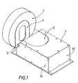
- FIGS 1 and 2 illustrate diagrammatically an advantageous embodiment of the bagging device according to the invention.
- the device comprises a loading device having a bottom plate 5 and a side plate 6 substantially perpendicular to the bottom plate.
- a roll is placed vertically on the plate 5 bearing against the side plate 6.
- the term vertically expresses the fact that the roll has a substantially horizontal winding axis (B).
- the bottom plate is coupled by means of an intermediate part 11 to a motor 8 by means, for example, of a belt 12.
- the side plate 6 is, according to the embodiment illustrated, mounted independently of the bottom plate but is designed so as to be driven by the pivoting movement of the bottom plate (in the direction indicated by the arrow C).
- the side plate 6 is provided with an oblong hole, disposed so as to coincide substantially with the core of the roll so as to be able to insert therein an insert or plug designed to stiffen the roll of web product.
- the roll has been loaded onto the plate 5, an operator places a bag 2 on top, also enclosing the side plate 6 in the bag.
- the roll is then pivoted by means of the motor 8 onto the support surface 7 adjacent to the loading means, thereby gripping the corresponding face of the bag 2 between the support 7 and the side plate 6.
- the side plate has a surface area sufficient, firstly, to hold the roll correctly during its pivoting movement onto the surface 7, and secondly, to hold the bag adequately when the roll is pushed to the bottom 4 of the bag.
- the loading means 5, 6, 11 and the roll 1 are depicted in the initial position, substantially vertical (unbroken lines) and in the pivoted position, substantially horizontal (broken lines).
- the motor is controlled so as to rotate in a first direction of rotation to pivot the roll 1 onto the support surface 7, detection means being provided to detect the end of travel of the roll.
- the control means 13 reverse the direction of rotation of the motor so as to return the bottom plate 5 to its horizontal loading position, means also being provided for detecting the end of travel of the plate.
- the plate 7 has a recess 9 designed to receive the side plate 6 after tilting, the recess being such that the surface of the side plate 6 in contact with the roll 1 is substantially aligned with the non-recessed surface of the plate 7.
- the support surface 7 defines, with the other lateral surfaces 14, 15, a protective housing for the motor 8.
- the roll 1 When the roll is pivoted onto the support surface 7, and after the free end of the bag has been cleared by retracting the plate 5, the roll 1 is pushed to the bottom of the bag, either by an operator, or automatically by means of a pushing device controlled, for example, by a ram (not shown). As mentioned above, with the bag held gripped between the surface 7 and the plate 6 under the effect of the weight of the roll, it does not move appreciably when the roll is pushed to the bottom of the bag. The bag can then be removed from the bagging station.
- means are advantageously provided, downstream of the device, for producing a fold at the open end of the bag.
- Means (not shown) can also be provided for applying an adhesive to the fold so as to hold the bag in the closed position.
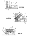
- FIGS 3A-3F illustrate diagrammatically the operation of the bagging device according to the invention.
- the roll 1 is placed on the plate 5 in abutment against the side plate 6.
- the roll is in a substantially vertical position.
- a bag 2 is disposed by its open end on the roll 1 so as to also enclose the side plate 6.
- the motor 8 is actuated so as to cause the plate 5 (and the roll) to pivot in a controlled manner about the axis A onto the support surface 7.
- the roll is in a substantially horizontal position on the surface 7, a part of the bag being wedged between the surface 7 and the side plate 6.
- the motor 8 is actuated so as to drive the bottom plate 5 in the opposite direction so as to clear the open end of the bag 1.
- the device that has just been described is particularly advantageous in that it enables the operation of bagging rolls of web products to be facilitated and automated. Furthermore, it considerably limits any risk of damage to the product to be bagged.
Landscapes
- Engineering & Computer Science (AREA)
- Mechanical Engineering (AREA)
- Packaging Of Special Articles (AREA)
- Container Filling Or Packaging Operations (AREA)
Claims (10)
- Vorrichtung zum Einsetzen einer Rolle (1) eines um eine Achse gewickelten bahnförmigen Materials in eine Hülle (2) mit einem offenen Ende (3) und einem geschlossenen Ende (4), gekennzeichnet durcha) Beschickungsmittel (5, 6) zum Aufnehmen der Rolle derart, dass sich die Rollenachse (B) im wesentlichen horizontal erstreckt, wobei die Beschickungsmittel eine Bodenplatte (5) und eine dazu im wesentlichen senkrechte Seitenplatte (6) aufweisen und derart angeordnet sind, dass die Hülle mit ihrem offenen Ende über der Rolle anordenbar ist und dabei die Seitenplatte umschließt,b) eine Auflagefläche (7), die im wesentlichen horizontal und den Beschickungsmitteln (5, 6) benachbart angeordnet ist,c) einen Motor (8) zum Antreiben der Beschickungsmittel (5, 6), wobei der Motor eine Schwenkbewegung der Rolle (Pfeilrichtung C) auf die Auflagefläche (7) bewirkt und eine der Seiten der Hülle zwischen der Auflagefläche (7) und der Seitenplatte erfasst, undd) Mittel zum Zurückziehen der Bodenplatte derart, dass das offene Ende der Hülle frei ist, wodurch die Rolle in diese hineinschiebbar ist.
- Vorrichtung nach Anspruch 1, dadurch gekennzeichnet, dass die Vorrichtung Mittel zum automatischen Hineinschieben der Rolle in die Hülle aufweist.
- Vorrichtung nach Anspruch 1 oder 2, dadurch gekennzeichnet, dass die Auflagefläche (7) eine Aussparung (9) aufweist, in der die Seitenplatte (6) derart aufnehmbar ist, dass die mit der Rolle in Berührung befindliche Fläche der Seitenplatte im wesentlichen mit dem nicht ausgesparten Teil der Auflagefläche (7) ausgerichtet ist.
- Vorrichtung nach einem der Ansprüche 1 bis 3, dadurch gekennzeichnet, dass der mit der Bodenplatte (5) verbundene Motor (8) in seiner Drehrichtung umkehrbar ist, wobei in der ersten Drehrichtung die Rolle auf die Auflagefläche schwenkbar ist und in der zweiten Drehrichtung die Bodenplatte (5) zurückziehbar ist.
- Vorrichtung nach einem der Ansprüche 1 bis 4, dadurch gekennzeichnet, dass die Vorrichtung Mittel aufweist zum automatischen Herstellen eines Falzes am offenen Ende der Hülle derart, dass diese schließbar ist.
- Vorrichtung nach Anspruch 5, dadurch gekennzeichnet, dass die Vorrichtung Mittel aufweist zum automatischen Aufbringen eines Klebstoffes auf die Falzung derart, dass die Hülle in ihrem geschlossenen Zustand haltbar ist.
- Verfahren zum Einsetzen einer Rolle (1) eines um eine Achse gewickelten bahnförmigen Materials in eine Hülle (2) mit einem offenen Ende (3) und einem geschlossenen Ende (4), gekennzeichnet durch die Schritte:a) Anordnen der Rolle auf Beschickungsmitteln (5, 6) derart, dass die Rollenachse (B) sich im wesentlichen horizontal erstreckt, wobei die Beschickungsmittel eine Bodenplatte (5) und eine dazu im wesentlichen senkrechte Seitenplatte (6) aufweisen und wobei eine im wesentlichen horizontale Auflagefläche (7) den Beschickungsmitteln (5, 6) benachbart angeordnet ist,b) Anordnen der Hülle (2) mit ihrem offenen Ende (3) auf der Rolle (1) derart, dass die Hülle auch die Seitenplatte umschließt,c) Antreiben der Beschickungsmittel (5, 6) derart, dass die Rolle eine Schwenkbewegung (Pfeilrichtung C) auf die Auflagefläche (7) ausführt und eine der Seiten der Hülle zwischen der Auflagefläche (7) und der Seitenplatte erfasst,d) Zurückziehen der Bodenplatte derart, dass das offene Ende der Hülle frei ist, unde) Einschieben der Rolle in die Hülle.
- Verfahren nach Anspruch 7, gekennzeichnet durch den Schritt:
f) Herstellen eines Falzes am offenen Ende der Hülle derart, dass diese schließbar ist. - Verfahren nach Anspruch 8, gekennzeichnet durch den Schritt:
g) Aufbringen eines Klebstoffes auf den Falz derart, dass die Hülle in ihrem geschlossenen Zustand haltbar ist. - Verfahren nach einem der Ansprüche 7 bis 9, dadurch gekennzeichnet, dass das bahnförmige Material ein lichtempfindliches Material ist und dass die Hülle aus einem lichtdichten Material hergestellt ist.
Applications Claiming Priority (2)
| Application Number | Priority Date | Filing Date | Title |
|---|---|---|---|
| FR9515011 | 1995-12-14 | ||
| FR9515011A FR2742422B1 (fr) | 1995-12-14 | 1995-12-14 | Procede et dispositif pour ensacher un rouleau de produit en bande |
Publications (2)
| Publication Number | Publication Date |
|---|---|
| EP0779208A1 EP0779208A1 (de) | 1997-06-18 |
| EP0779208B1 true EP0779208B1 (de) | 2001-08-08 |
Family
ID=9485617
Family Applications (1)
| Application Number | Title | Priority Date | Filing Date |
|---|---|---|---|
| EP19960420353 Expired - Lifetime EP0779208B1 (de) | 1995-12-14 | 1996-12-09 | Verfahren und Vorrichtung zum Verpacken einer Rolle Bandmaterial in einem Sack |
Country Status (3)
| Country | Link |
|---|---|
| EP (1) | EP0779208B1 (de) |
| DE (1) | DE69614349T2 (de) |
| FR (1) | FR2742422B1 (de) |
Families Citing this family (2)
| Publication number | Priority date | Publication date | Assignee | Title |
|---|---|---|---|---|
| CN112455768B (zh) * | 2020-04-15 | 2024-11-08 | 青岛海科佳智能科技股份有限公司 | 袋口卷口机构 |
| CN112093135B (zh) * | 2020-10-26 | 2022-01-11 | 重庆电子工程职业学院 | 一种电商用快递打包机 |
Family Cites Families (2)
| Publication number | Priority date | Publication date | Assignee | Title |
|---|---|---|---|---|
| US3473290A (en) * | 1967-04-07 | 1969-10-21 | Phillips Petroleum Co | Apparatus for stacking and packing articles |
| US4833861A (en) * | 1988-03-31 | 1989-05-30 | Hale Everett D | Sliced bread stacking apparatus |
-
1995
- 1995-12-14 FR FR9515011A patent/FR2742422B1/fr not_active Expired - Fee Related
-
1996
- 1996-12-09 EP EP19960420353 patent/EP0779208B1/de not_active Expired - Lifetime
- 1996-12-09 DE DE1996614349 patent/DE69614349T2/de not_active Expired - Fee Related
Also Published As
| Publication number | Publication date |
|---|---|
| DE69614349D1 (de) | 2001-09-13 |
| EP0779208A1 (de) | 1997-06-18 |
| FR2742422B1 (fr) | 1998-01-16 |
| DE69614349T2 (de) | 2002-05-16 |
| FR2742422A1 (fr) | 1997-06-20 |
Similar Documents
| Publication | Publication Date | Title |
|---|---|---|
| US6907711B2 (en) | Sheet package producing system, sheet handling device, and fillet folding device | |
| CA1308643C (en) | Device and method for the spreading of the top wrapping film in wrapping | |
| US4696615A (en) | Copying machine | |
| US5619838A (en) | Method anf apparatus for applying edge protectors | |
| JPH05112386A (ja) | ロールをストレツチラツプで包装する方法及び装置 | |
| EP0779208B1 (de) | Verfahren und Vorrichtung zum Verpacken einer Rolle Bandmaterial in einem Sack | |
| JPH09100026A (ja) | ロール状物の搬送システム | |
| JPH09110015A (ja) | テープ貼り付け装置 | |
| EP3868692B1 (de) | Verbesserte abfüllmaschine und verfahren zu deren betrieb | |
| JP3745788B2 (ja) | ロール紙開梱仕立て装置 | |
| FR2497781A1 (fr) | Procede pour changer les bobines et les mandrins des machines d'enroulement sans axe | |
| US6708842B2 (en) | Method and device for unpacking a stack in a sleeve | |
| CN111824486A (zh) | 茶包封装机 | |
| EP0465370A2 (de) | Verfahren zum Umhüllen einer palettisierten Ladung mit einer Haube aus Dehnfolie | |
| JP2808384B2 (ja) | 巻取ボビンの自動処理装置 | |
| JP2767715B2 (ja) | 梱包体における結束バンド回収処理方法およびその装置 | |
| FI87639B (fi) | Foerfarande och anordning foer att linda en vara | |
| JP3340216B2 (ja) | 包装用袋体の自動蓋掛け装置 | |
| JPH06345038A (ja) | 線材コイル自動梱包方法 | |
| JPH0579573B2 (de) | ||
| FR2700321A1 (fr) | Dispositif de préhension et de transport d'un cylindre de révolution posé horizontalement sur un support. | |
| JP3118479B2 (ja) | 包装装置 | |
| JP3429021B2 (ja) | 手提げテープ取り付け装置 | |
| JP2950669B2 (ja) | 梱包材除去装置 | |
| US3195291A (en) | Apparatus for cutting glue spots attaching a liner to an outer carton |
Legal Events
| Date | Code | Title | Description |
|---|---|---|---|
| PUAI | Public reference made under article 153(3) epc to a published international application that has entered the european phase |
Free format text: ORIGINAL CODE: 0009012 |
|
| AK | Designated contracting states |
Kind code of ref document: A1 Designated state(s): DE FR GB |
|
| 17P | Request for examination filed |
Effective date: 19971031 |
|
| GRAG | Despatch of communication of intention to grant |
Free format text: ORIGINAL CODE: EPIDOS AGRA |
|
| 17Q | First examination report despatched |
Effective date: 20001113 |
|
| GRAG | Despatch of communication of intention to grant |
Free format text: ORIGINAL CODE: EPIDOS AGRA |
|
| GRAH | Despatch of communication of intention to grant a patent |
Free format text: ORIGINAL CODE: EPIDOS IGRA |
|
| RBV | Designated contracting states (corrected) |
Designated state(s): DE FR GB |
|
| RBV | Designated contracting states (corrected) |
Designated state(s): DE FR GB NL |
|
| GRAH | Despatch of communication of intention to grant a patent |
Free format text: ORIGINAL CODE: EPIDOS IGRA |
|
| RAP1 | Party data changed (applicant data changed or rights of an application transferred) |
Owner name: EASTMAN KODAK COMPANY |
|
| GRAA | (expected) grant |
Free format text: ORIGINAL CODE: 0009210 |
|
| AK | Designated contracting states |
Kind code of ref document: B1 Designated state(s): DE FR GB |
|
| RBV | Designated contracting states (corrected) |
Designated state(s): DE FR GB |
|
| REF | Corresponds to: |
Ref document number: 69614349 Country of ref document: DE Date of ref document: 20010913 |
|
| ET | Fr: translation filed | ||
| REG | Reference to a national code |
Ref country code: GB Ref legal event code: IF02 |
|
| PLBE | No opposition filed within time limit |
Free format text: ORIGINAL CODE: 0009261 |
|
| STAA | Information on the status of an ep patent application or granted ep patent |
Free format text: STATUS: NO OPPOSITION FILED WITHIN TIME LIMIT |
|
| 26N | No opposition filed | ||
| PGFP | Annual fee paid to national office [announced via postgrant information from national office to epo] |
Ref country code: GB Payment date: 20031105 Year of fee payment: 8 |
|
| PGFP | Annual fee paid to national office [announced via postgrant information from national office to epo] |
Ref country code: FR Payment date: 20031201 Year of fee payment: 8 |
|
| PGFP | Annual fee paid to national office [announced via postgrant information from national office to epo] |
Ref country code: DE Payment date: 20031230 Year of fee payment: 8 |
|
| PG25 | Lapsed in a contracting state [announced via postgrant information from national office to epo] |
Ref country code: GB Free format text: LAPSE BECAUSE OF NON-PAYMENT OF DUE FEES Effective date: 20041209 |
|
| PG25 | Lapsed in a contracting state [announced via postgrant information from national office to epo] |
Ref country code: DE Free format text: LAPSE BECAUSE OF NON-PAYMENT OF DUE FEES Effective date: 20050701 |
|
| GBPC | Gb: european patent ceased through non-payment of renewal fee |
Effective date: 20041209 |
|
| PG25 | Lapsed in a contracting state [announced via postgrant information from national office to epo] |
Ref country code: FR Free format text: LAPSE BECAUSE OF NON-PAYMENT OF DUE FEES Effective date: 20050831 |
|
| REG | Reference to a national code |
Ref country code: FR Ref legal event code: ST |