EP0779184A1 - Apparatus for restraining a driver of a vehicle - Google Patents
Apparatus for restraining a driver of a vehicle Download PDFInfo
- Publication number
- EP0779184A1 EP0779184A1 EP96118551A EP96118551A EP0779184A1 EP 0779184 A1 EP0779184 A1 EP 0779184A1 EP 96118551 A EP96118551 A EP 96118551A EP 96118551 A EP96118551 A EP 96118551A EP 0779184 A1 EP0779184 A1 EP 0779184A1
- Authority
- EP
- European Patent Office
- Prior art keywords
- cover part
- steering wheel
- inner cover
- restraint
- hub plate
- Prior art date
- Legal status (The legal status is an assumption and is not a legal conclusion. Google has not performed a legal analysis and makes no representation as to the accuracy of the status listed.)
- Withdrawn
Links
Images


Classifications
-
- B—PERFORMING OPERATIONS; TRANSPORTING
- B60—VEHICLES IN GENERAL
- B60R—VEHICLES, VEHICLE FITTINGS, OR VEHICLE PARTS, NOT OTHERWISE PROVIDED FOR
- B60R21/00—Arrangements or fittings on vehicles for protecting or preventing injuries to occupants or pedestrians in case of accidents or other traffic risks
- B60R21/02—Occupant safety arrangements or fittings, e.g. crash pads
- B60R21/16—Inflatable occupant restraints or confinements designed to inflate upon impact or impending impact, e.g. air bags
- B60R21/20—Arrangements for storing inflatable members in their non-use or deflated condition; Arrangement or mounting of air bag modules or components
- B60R21/203—Arrangements for storing inflatable members in their non-use or deflated condition; Arrangement or mounting of air bag modules or components in steering wheels or steering columns
-
- B—PERFORMING OPERATIONS; TRANSPORTING
- B62—LAND VEHICLES FOR TRAVELLING OTHERWISE THAN ON RAILS
- B62D—MOTOR VEHICLES; TRAILERS
- B62D1/00—Steering controls, i.e. means for initiating a change of direction of the vehicle
- B62D1/02—Steering controls, i.e. means for initiating a change of direction of the vehicle vehicle-mounted
- B62D1/04—Hand wheels
Definitions
- the present invention relates to a vehicle occupant restraint apparatus for restraining a driver of a vehicle, and particularly relates to a vehicle occupant restraint apparatus for use with a vehicle steering column.
- An inflatable vehicle occupant restraint such as an air bag, is inflated to protect an occupant of a vehicle upon the occurrence of a vehicle collision.
- the air bag is part of a vehicle occupant restraint system which further includes a collision sensor and an inflator.
- the collision sensor senses vehicle conditions which indicate the occurrence of a collision.
- the inflator is actuated.
- the inflator then emits inflation fluid which inflates the air bag into the vehicle occupant compartment to restrain an occupant of the vehicle from forcefully striking parts of the vehicle as a result of the collision.
- An air bag and an inflator are typically assembled together as parts of an air bag module which is separate from the collision sensor.
- the module includes a deployment door or cover which extends over the air bag and the inflator to conceal those parts of the module from the vehicle occupant compartment.
- the inflation fluid emitted from the inflator begins to inflate the air bag, it moves the air bag forcefully outward against the deployment door.
- the deployment door is ruptured by the force of the fluid pressure in the air bag, and is moved out of the path of the air bag as the inflation fluid continues to inflate the air bag outward into the vehicle occupant compartment.
- An air bag module is located in the vehicle adjacent to the vehicle occupant compartment, such as in the instrument panel or on the steering column. When the module is located on the steering column, it is attached to the steering wheel on the steering column.
- the steering wheel unit comprises a plurality of parts which are interconnected separately from the steering column.
- the parts of the steering wheel unit include a vehicle steering wheel structure, an inflatable vehicle occupant restraint, and an inflator housing.
- the parts of the steering wheel unit further include cover means for covering the restraint and the inflator housing on the steering wheel structure.
- the steering wheel structure includes a rim, at least one spoke, and a hub plate which comprises means for supporting the rim and the spoke for rotation about an axis.
- the hub plate further comprises reaction plate means for supporting the inflator housing on the steering wheel structure.
- the cover means comprises inner and outer cover parts which respectively include inner and outer deployment door layers extending over the restraint. Each of the cover parts is connected directly to the steering wheel structure.
- the inner cover part has a connector portion projecting away from the outer cover part.
- the connector portion of the inner cover part is fastened directly to the hub plate by fasteners.
- the inner cover part and the steering wheel structure together comprise means for snapping into a locked condition to establish a mechanical interlock between the inner cover part and the steering wheel structure.
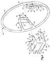
- a vehicle occupant restraint apparatus 10 comprising a first embodiment of the present invention is shown schematically in Figs. 1-3.
- the apparatus 10 includes a vehicle steering wheel unit 12 and a vehicle steering column 14.
- the steering wheel unit 12 is an assembled unit of parts which are interconnected separately from the steering column 14, as shown in Fig. 1.
- the steering wheel unit 12 is installed on the steering column 14.
- the steering wheel unit 12 is then coupled to a steering shaft 18 in the steering column 14 for rotation about an axis 19 with the shaft 18.
- the parts of the steering wheel unit 12 include an inflator 20 and a particular type of inflatable vehicle occupant restraint 22 which is commonly referred to as an air bag.
- the air bag 22 is inflatable from a folded, uninflated condition, as shown in Figs. 1 and 2, to an unfolded, inflated condition, as shown in Fig. 3. When the air bag 22 is being inflated, it moves toward the driver of the vehicle. The air bag 22 then restrains movement of the driver toward the steering wheel unit 12 to help protect the driver from a forceful impact with the steering wheel unit 12 or other parts of the vehicle.
- the inflator 20 is an electrically actuatable source of inflation fluid for inflating the air bag 22.
- the inflator 20 contains an ignitable gas generating material for generating a large volume of gas.
- the inflator 20 may alternatively contain a stored quantity of pressurized inflation fluid, or a combination of pressurized inflation fluid and ignitable material for heating the inflation fluid.
- the inflator 20 is included in an electrical circuit 23.
- the electrical circuit 23 further includes a power source 24 and a normally open switch 26.
- the power source 24 is preferably the vehicle battery.
- the switch 26 is part of a sensor 28 which senses a condition indicating the occurrence of a vehicle collision. Such a condition may comprise, for example, sudden vehicle deceleration caused by a collision. If the collision-indicating condition is above a predetermined threshold level, it indicates the occurrence of a collision for which inflation of the air bag 22 is desired to restrain movement of the driver of the vehicle, as described above.
- the sensor 28 then closes the switch 26, and electric current is directed through the inflator 20 to actuate the inflator 20.
- the inflator 20 rapidly emits a large volume of inflation fluid which flows into the air bag 22 to inflate the air bag 22.
- the cover 30 which encloses the air bag 22 and the inflator 20.
- the cover 30 includes first and second deployment door panels 32 and 34 which extend over the air bag 22.
- the deployment door panels 32 and 34 are held in closed positions, as shown in Figs. 1 and 2, by a rupturable section 36 of the cover 30.
- the air bag 22 then ruptures the rupturable section 36 of the cover 30 and moves the deployment door panels 32 and 34 pivotally outward, as shown in Fig. 3.
- the parts of the steering wheel unit 12 further include a steering wheel armature 40.
- the armature 40 is a metal structure with a rim 42 and spokes 44.
- the rim 42 has an axis of rotation 45.
- the spokes 44 extend equal distances from the rim 42 in generally radial directions, and also extend equal distances from the rim 42 in an axially inward direction, i.e., in a direction extending along the axis 45 from left to right as viewed in Figs. 4 and 5.
- Each spoke 44 includes a mounting tab 46 at its inner end.
- Each spoke 44 further includes a pair of spoke arms 48 which converge toward the corresponding mounting tab 46, and a stiffener 50 which extends between the spoke arms 48.
- a corresponding pair of threaded mounting studs 52 project axially inward from each mounting tab 46.
- the armature 40 is preferably made of magnesium or aluminum, but can be made of any other suitable metal or other material known in the art.
- the cover 30 includes inner and outer cover parts 56 and 58.
- the inner cover part 56 in the first embodiment of the present invention has a non-woven structure defined by a continuous body of molded plastic material.
- the plastic material of which the inner cover part 56 is formed may have any suitable composition known in the art, but a thermoplastic material is preferred.
- the inner cover part 56 has the configuration of a generally rectangular box with a base wall 60, a pair of opposite side walls 62, and a pair of opposite end walls 64.
- the walls 60-64 of the inner cover part 56 together define a compartment 66 with an opening 68 opposite the base wall 60.
- the inner cover part 56 further has a pair of connector flaps 70.
- Each connector flap 70 projects from a corresponding side wall 62, and is pivotal about a corresponding fold line 72 at the juncture of the connector flap 70 and the side wall 62. Additionally, each connector flap 70 has a pair of connector tabs 74 with a corresponding pair of apertures 76.
- the base wall 60 of the inner cover part 56 has first and second pivotal deployment door portions 80 and 82.
- the deployment door portions 80 and 82 of the base wall 60 have generally rectangular shapes, with the first deployment door portion 80 being somewhat larger than the second deployment door portion 82.
- the first deployment door portion 80 of the base wall 60 defines an inner layer of the first deployment door panel 32 (Figs. 1-3).
- the second deployment door portion 82 of the base wall 60 defines an inner layer of the second deployment door panel 34.
- the boundaries of the deployment door portions 80 and 82 are defined by a stress riser 84 and a pair of hinges 88.
- the stress riser 84 has an H-shaped configuration extending along three sides of each of the two deployment door portions 80 and 82.
- the stress riser 84 has a structure defined by a thinned or notched section of the plastic material of the inner cover part 56.
- Each hinge 88 extends along the fourth side of the corresponding deployment door portion 80 or 82, and is defined by the plastic material at the juncture of the base wall 60 and the adjacent side wall 62.
- the hinges 88 also may have relatively thin structures so that the plastic material at the hinges 88 will bend more easily than the plastic material adjacent to the hinges 88. Such hinge structures also are known in the art.
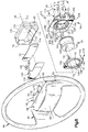
- the armature 40 and the cover parts 56 and 58 are shown in their interconnected relationship in Figs. 5 and 6. Those interconnected parts of the steering wheel unit 12 define a steering wheel subassembly 89.
- the outer cover part 58 extends over the armature 40 and the inner cover part 56 to conceal them from view from above and beside the steering column 14 (Figs. 2 and 3).
- the outer cover part 58 extends continuously along and around the rim 42 of the armature 40, along and around the arms 48 and the stiffeners 50 at the spokes 44, and fully over the exterior surfaces of the walls 60-64 of the inner cover part 56.
- the outer cover part 58 does not extend over the inner sides of the mounting tabs 46 where the studs 52 project from the mounting tabs 46, and does not extend over the connector flaps 70.
- the studs 52 and the connector flaps 70 project axially inward from the outer cover part 58 for connection directly with other parts of the steering wheel unit 12.
- the subassembly 89 is formed by first placing the armature 40 and the inner cover part 56 together in a mold cavity having the size and shape of the subassembly 89.
- the outer cover part 58 is then formed over the armature 40 and the inner cover part 56 upon injection of a plastic material into the mold cavity.
- plastic material may be either thermoplastic or thermosetting, and may have any suitable composition known in the art.
- the outer cover part 58 is thus constructed as a continuous body of molded plastic material, as shown in Fig. 6.
- the plastic material of the outer cover part 58 becomes bonded to the plastic material of the inner cover part 56 at the exterior surfaces of the walls 60-64.
- the outer cover part 58 then supports the inner cover part 56 at a location between the mounting tabs 46 at the inner ends of the spokes 44, with the compartment opening 68 facing inward along the axis 45 of the rim 42.
- the outer cover part 58 has first and second pivotal deployment door portions 90 and 92.
- the first deployment door portion 90 of the outer cover part 58 overlies the first deployment door portion 80 of the inner cover part 56.
- the first deployment door portion 90 of the outer cover part 58 thus defines an outer layer of the first deployment door panel 32 (Figs. 1-3).
- the second deployment door portion 92 of the outer cover part 58 overlies the second deployment door portion 82 of the inner cover part 56, and defines an outer layer of the second deployment door panel 34.
- An H-shaped stress riser 94 in the outer cover part 58 extends along three sides of each of the two deployment door portions 90 and 92 between the opposite ends of a corresponding pair of hinges 98.
- the stress riser 94 and the hinges 98 in the outer cover part 58 adjoin, and are substantially coextensive with, the stress riser 84 and the hinges 88 in the inner cover part 56.
- the adjoining stress risers 84 and 94 together define the rupturable section 36 (Figs. 1 and 2) of the cover 30.
- the structure of the stress riser 94 in the outer cover part 58 does not affect the contour of an adjacent outer side surface 102 of the outer cover part 58.
- the outer side surface 102 thus extends continuously over the rupturable section 36 of the cover 30 such that the outline of the deployment door panels 32 and 34 is not visible at the outer side surface 102.
- the steering wheel unit 12 also includes a horn actuator 120 and a backing plate 122 for the horn actuator 120.
- the horn actuator 120 comprise a switch panel 130 with approximately the same size and shape as the first deployment door panel 32 on the cover 30.
- the switch panel 130 is a membrane switch of known construction, and thus includes electrical contact members that are pressed against each other to complete an electrical circuit upon compression of the switch panel 130 across its thickness.
- a terminal portion 132 of the horn actuator 120 projects from the switch panel 130 for connection in an electrical circuit with the vehicle horn (not shown).
- the backing plate 122 supports the switch panel 130 against the base wall 60 of the inner cover part 56 when the steering wheel unit 12 has been fully assembled.
- the parts of the steering wheel unit 12 shown in Fig. 6 further include the inflator 20, the air bag 22, and a retainer 134 for the inflator 20 and the air bag 22.
- the retainer 134 includes a planar frame 140.
- the frame 140 has a square peripheral shape with rounded corners.
- An outer flange 142 projects from the periphery of the frame 140 in a direction extending axially outward, as shown with reference to the axis 45 of the armature rim 42.
- An inner flange 144 also projects axially outward from the frame 140, and defines a circular central opening 148 through the retainer 134.
- the opening 148 is centered on an axis 149 which is offset from the axis 45 of the armature rim 42.
- Four threaded mounting studs 150 project axially inward from the frame 140, with each stud 150 being located adjacent to a corresponding one of the four rounded corners of the frame 140.
- the inflator 20 has a cylindrical housing 160.
- the housing 160 is coaxial with the opening 148 in the retainer 134, and has a diameter that is just slightly less than the diameter of the opening 148.
- a circumferentially extending array of gas outlet openings 162 is located near one end of the housing 160.
- An annular mounting flange 164 projects radially outward from the other end of the housing 160.
- the air bag 22 is shown in Fig. 6 in the folded, uninflated condition described above with reference to Figs. 1 and 2.
- An edge portion 170 of the air bag 22 defines a circular inlet opening 172 which is located at the axially inner side of the air bag 22, as shown with reference to the axis 45 of the armature rim 42.
- the inlet opening 172 in the air bag 22 has a central axis 173 which, like the axis 149 of the retainer opening 148, is offset from the axis 45.
- the retainer 134 is shown in Fig. 6 separately from the air bag 22, those skilled in the art understand that the retainer 134 is inserted through the inlet opening 172 in the air bag 22 before the air bag 22 is folded.
- the mounting studs 150 on the retainer 134 are received through corresponding apertures 174 in the edge portion 170 of the air bag 22 so as to project axially away from the air bag 22.
- An air bag cover 176 is wrapped around the air bag 22 to hold the air bag 22 in its folded configuration, and also to protect the folded air bag 22 from the ambient atmosphere.
- the air bag cover 176 is preferably formed of a thin, rupturable plastic material, as known in the art.
- a hub plate 190 supports the other parts of the steering wheel unit 12 on the steering shaft 18.
- the hub plate 190 has a planar outer side surface 192.
- the outer side surface 192 is perpendicular to the axis 45 of the armature rim 42, and faces axially outward.
- a planar surface 194 with a circular shape is parallel to, and recessed axially from, the outer side surface 192.
- An annular shoulder surface 196 also is parallel to the outer side surface 192, and is located axially between the circular surface 194 and the outer side surface 192.
- the shoulder surface 196 and the circular surface 194 are centered on an axis 197 which also is offset from the axis 45.
- a bore 198 extends through the hub plate 192 along the axis 45.
- An opening 200 extends through the hub plate 192 along the axis 197.
- a first group of apertures 202 also extend through the hub plate 190. The apertures 202 are located radially outward of the shoulder surface 196 in axial alignment with the mounting studs 150 on the retainer 134. Additionally, four mounting bosses 204 project axially outward from the periphery of the outer side surface 192.
- a second group of apertures 206 are located at the outer ends 208 of the mounting bosses 204. The apertures 206 in the mounting bosses 204 are aligned axially with the mounting studs 52 on the armature 40.
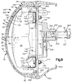
- the other parts of the steering wheel unit 12 are interconnected with the subassembly 89 in the axial alignment in which they are shown in Figs. 6 and 7.
- the horn actuator 120 and the backing plate 122 are first moved into the compartment 66 (Fig. 5) in the inner cover part 56 through the opening 68.
- the base wall 60 of the inner cover part 56 has a plurality of ribs 216, one of which is shown in Fig. 7, and has a pair of supporting structures 218 extending across the opposite ends of the ribs 216.
- the switch panel 130 is received against the ribs 216.
- the backing plate 122 is held against the switch panel 130 by the supporting structures 218, and thus holds the switch panel 130 against the ribs 216.
- the switch panel 130 could be fastened directly to the ribs 216, or to other portions of the base wall 60, by heat staking, sonic welding, or the like.
- the switch panel 130 is thus supported for compression across its thickness between the ribs 216 and the backing plate 122 upon the application of pressure against the cover 30 by an occupant of the vehicle.
- the terminal portion 132 of the horn actuator 120 can be connected in an electrical circuit, as noted above, in any suitable manner known in the art.
- the air bag 22, the retainer 134, and the inflator 20 are placed together on the hub plate 190.
- the inflator housing 160 is received coaxially through the inlet opening 172 at the edge portion 170 of the air bag 22.
- the inflator housing 160 is thus received coaxially through the opening 148 in the retainer 134.
- the mounting flange 164 on the inflator 20, which then projects radially outward of the inlet opening 172, is moved axially into abutment with the shoulder surface 196 on the hub plate 190.
- the mounting studs 150 on the retainer 134 are simultaneously received through the apertures 202 at the outer side surface 192 of the hub plate 190.
- the hub plate 190 is then moved axially against the subassembly 89 (Fig. 6).
- the outer ends 208 of the mounting bosses 204 are moved into abutment with the tabs 46 (Fig. 4) on the spokes 44, with the studs 52 being received through the corresponding apertures 206.
- a corresponding plurality of nuts 210 are received over the studs 52 to fasten the hub plate 190 directly to the armature 40.
- the inflator 20 and the air bag 22 are carried by the hub plate 190 into the compartment 66 through the opening 68.
- the mounting flaps 70 on the inner cover part 56 are moved pivotally into abutting engagement with the hub plate 190 at an inner side surface 212 opposite the outer side surface 192.
- the studs 150 projecting axially inward from the hub plate 190 are then received through the apertures 76 in the mounting flaps 70.
- Four corresponding nuts 214 are received over the studs 150 to fasten the mounting flaps 70 directly to the hub plate 190.
- the edge portion 170 of the air bag 22 is clamped between the frame portion 140 of the retainer 134 and the outer side surface 192 of the hub plate 190.
- the flange 164 on the inflator 20 is similarly clamped between the frame portion 140 of the retainer 134 and the shoulder surface 196 of the hub plate 190.
- the hub plate 190 thus functions as a reaction plate which directly engages the inflator 20 to help secure the inflator 20 against movement under a thrust, if any, developed by the gas emerging from the outlet openings 162.
- the opening 200 (Fig. 6) in the hub plate 190 provides access for connection of the inflator 20 in the electrical circuit 23 shown in Figs. 2 and 3.
- the hub plate 190 has a neck 220 which projects axially away from the inner side surface 212 and through which the bore 198 extends along the axis 45.
- the neck 220 has a flat surface 222 at one side of the bore 198, and is thus shaped to receive a mating end portion 224 of the steering shaft 18.
- a set screw 226 is supported in a radially extending bore 228 in the neck 220 of the hub plate 190, and is movable into the axially extending bore 198. When the set screw 226 is moved into the bore 198, it engages the end portion 224 of the steering shaft 18 so as to press the neck 220 axially against an adjacent flange 229 on the steering shaft 18. The set screw 226 then holds the steering wheel unit 12 securely on the steering shaft 18.
- a skirt portion 230 of the cover 30 is shown in Fig. 7.
- the skirt portion 230 projects axially inward from the outer cover part 58, and extends entirely around the axis 45.
- An access opening 232 in the skirt portion 230 is aligned with the radially extending bore 228 in the hub plate 190 to provide access to the set screw 226 and the steering shaft 18 from a location beside the steering wheel unit 12.
- such access is provided radially from beside the steering wheel unit 12 rather than axially from the front of the steering wheel unit 12. This is because the set screw 226 is moved radially into engagement with the steering shaft 18 after the axially outer end 232 of the steering shaft 18 has been covered by the fully assembled steering wheel unit 12.
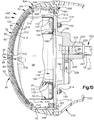
- a vehicle occupant restraint apparatus 250 comprising a second embodiment of the present invention is shown partially in Figs. 8 and 9.
- the partial view of the apparatus 250 shown in Fig. 8 corresponds with the partial view of the apparatus 10 shown in Fig. 7.
- the apparatus 250 is thus shown to include a steering wheel unit 252 which is installed on a steering column 254 after being assembled separately from the steering column 254.
- the steering column 254 is substantially the same as the steering column 14.
- the steering wheel unit 252 has many parts that are substantially the same as corresponding parts of the steering wheel unit 12.
- the steering wheel unit 252 has other parts that differ from the corresponding parts of the steering wheel unit 12.
- the differing parts of the steering wheel unit 252 include a steering wheel armature 260 and an inner cover part 262.
- the armature 260 differs from the armature 40 in that the armature 260 has a pair of bridge arms 264 extending between the spokes 44. Each bridge arm 264 has a plurality of locking apertures 266.
- the inner cover part 262 does not have mounting flaps like the mounting flaps 70 on the inner cover part 56. Instead, the side walls 62 of the inner cover part 262 have locking pins 268 with wedge-shaped end portions 270. The end portions 270 of the locking pins 268 snap into engagement with the bridge arms 264 to establish a mechanical interlock between the inner cover part 262 and the armature 260 upon movement of the locking pins 268 through the apertures 266.
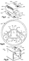
- a vehicle occupant restraint apparatus 300 comprising a third embodiment of the present invention is shown partially in Fig. 10.
- the apparatus 300 of Fig. 10 is substantially similar to the apparatus 250 of Fig. 8. This is indicated by the use of the same reference numbers in Figs. 8 and 10 for parts that are substantially the same in the second and third embodiments.
- the apparatus 300 differs from the apparatus 250 in that the apparatus 300 includes a steering wheel unit 302 with differently constructed inner and outer cover parts 304 and 306.
- the inner cover part 304 in the third embodiment is interlocked with the bridge arms 264 on the armature 260 in the same manner as described above with reference to the inner cover part 262 in the second embodiment.
- the outer cover part 306 in the third embodiment has a wraparound portion 308 extending around the bridge arms 264 and across the inner side of the inner cover part 304.
- a plurality of mounting studs 310 on the inner cover part 304 project inward through the wraparound portion 308 of the outer cover part 306.
- the inner cover part 304 is otherwise substantially encapsulated within the outer cover part 306.
- the mounting studs 310 further project through a backing plate 312, and are heat staked or welded to the backing plate 312.
- the mounting studs 310 and the backing plate 312 hold a switch panel 314 against a plurality of ribs 316 on the wraparound portion tabs 408 are preferably formed of metal, and are fixed to the scrims 404 by an adhesive or the like.
- the fourth embodiment of the present invention further includes a steering wheel armature 414.
- the armature 414 of Fig. 12 differs from the armature 260 of Fig. 9 in that the armature 414 has locking pins 416 in place of the apertures 266.
- the locking pins 416 are receivable through the apertures 410 (Fig. 11) in the mounting tabs 408 in the same manner that the locking pins 268 (Fig. 8) are receivable through the apertures 266.
- the inner cover parts 400 and 402 are interlocked with the armature 414 in substantially the same manner that the inner cover part 262 is interlocked with the armature 260.
- a subassembly similar to the subassembly 89 can be formed by injecting a plastic material into a mold cavity containing the armature 414 and the inner cover parts 400 and 402 so as to form an outer cover part (not shown) over the armature 414 and the inner cover parts 400 and 402.
- a fifth embodiment of the present invention includes a tether structure 500 (Fig. 13) which is wrapped around the folded air bag 22 in place of the air bag cover 176 (Fig. 6).
- a tether structure 500 (Fig. 13) which is wrapped around the folded air bag 22 in place of the air bag cover 176 (Fig. 6).
- the tether structure 500 has been wrapped around the folded air bag 22, it has the box-like configuration in which it is shown separately in Fig. 13.
- An inlet opening 502 in the tether structure 500 is then aligned with the inlet opening 172 in the air bag 22.
- a plurality of apertures 504 in the tether structure 500 are likewise aligned with the apertures 174 in the air bag 22.
- the apertures 504 in the tether structure 500 are thus located so as to receive the mounting studs 150 (Fig. 6) on the retainer 134.
- the air bag 22 When the air bag 22 is inflated, as described above, it moves forcefully outward against the tether structure 500. A pair of stress risers 506 in the tether structure 500 then rupture under stress induced by the inflation fluid pressure in the air bag 22.
- the tether structure 500 is formed of a woven fabric material which is the same or similar to the woven fabric material of which the air bag 22 is formed.
- the tether structure 500 may be formed of any other suitable material known in the art, such as a plastic material.
- each cover 30 in the preferred embodiments of the present invention has two generally rectangular deployment door panels 32 and 34 of differing sizes, but the number, shapes, and/or sizes of such deployment door panels could vary from those described above.
- vehicle name labels or the like can be mounted in or on the covers 30.
- the outer cover parts 58 would still be continuous bodies of molded plastic material which function to conceal the inflators 20, the air bags 22, and the armatures 40, 260, and 414 from view, as described above.
- the invention relates to an apparatus for use with a vehicle steering column, said apparatus comprising: a steering wheel unit comprising a plurality of parts, said parts including a vehicle steering wheel structure, an inflactable vehicle occupant restraint, an inflator housing, and cover means for covering said restraint and said inflator housing on said steering wheel structure.
Applications Claiming Priority (2)
| Application Number | Priority Date | Filing Date | Title |
|---|---|---|---|
| US572096 | 1984-01-19 | ||
| US08/572,096 US5615910A (en) | 1995-12-14 | 1995-12-14 | Apparatus for restraining a driver of a vehicle |
Publications (1)
| Publication Number | Publication Date |
|---|---|
| EP0779184A1 true EP0779184A1 (en) | 1997-06-18 |
Family
ID=24286335
Family Applications (1)
| Application Number | Title | Priority Date | Filing Date |
|---|---|---|---|
| EP96118551A Withdrawn EP0779184A1 (en) | 1995-12-14 | 1996-11-19 | Apparatus for restraining a driver of a vehicle |
Country Status (3)
| Country | Link |
|---|---|
| US (1) | US5615910A (ja) |
| EP (1) | EP0779184A1 (ja) |
| JP (1) | JP2895012B2 (ja) |
Cited By (1)
| Publication number | Priority date | Publication date | Assignee | Title |
|---|---|---|---|---|
| CN104724040A (zh) * | 2013-11-21 | 2015-06-24 | 福特全球技术公司 | 具有多种展开路径的驾驶员安全气囊模块 |
Families Citing this family (32)
| Publication number | Priority date | Publication date | Assignee | Title |
|---|---|---|---|---|
| US5692769A (en) * | 1995-09-01 | 1997-12-02 | Breed Automotive Technology, Inc. | Modular steering wheel and air bag combination |
| US5897133A (en) * | 1995-09-11 | 1999-04-27 | Trw Inc. | Steering wheel with integral air bag cover |
| DE29519700U1 (de) * | 1995-12-12 | 1996-04-11 | Trw Repa Gmbh | Fahrzeuglenkrad mit einem integrierten Fahrzeuginsassen-Rückhaltesystem |
| US5720494A (en) * | 1995-12-27 | 1998-02-24 | Toyoda Gosei Co., Ltd. | Steering wheel with air bag device |
| US5765864A (en) * | 1996-02-26 | 1998-06-16 | Winget; Larry J. | Unitary composite steering wheel and air bag cover assembly and method of making same |
| DE29605386U1 (de) * | 1996-03-22 | 1996-07-18 | Trw Repa Gmbh | Fahrzeuglenkrad für die Bestückung mit einem integrierten Gassack-Rückhaltesystem |
| JP3327104B2 (ja) * | 1996-03-27 | 2002-09-24 | 豊田合成株式会社 | ステアリングホイール |
| DE29615261U1 (de) * | 1996-09-02 | 1997-01-16 | Trw Repa Gmbh | Abdeckung eines in ein Fahrzeuglenkrad integrierten Gassack-Moduls |
| US6122992A (en) * | 1996-10-29 | 2000-09-26 | Trw Inc. | Steering wheel and air bag assembly attachment to a steering shaft |
| US5897132A (en) * | 1996-10-29 | 1999-04-27 | Trw Inc. | Steering wheel and air bag assembly attachment to a steering shaft |
| US6142504A (en) * | 1996-10-29 | 2000-11-07 | Trw Inc. | Steering wheel and air bag assembly attachment to a steering shaft |
| US6109646A (en) * | 1997-02-13 | 2000-08-29 | Toyoda Gosei Co., Ltd. | Steering wheel |
| AU749401B2 (en) * | 1997-02-19 | 2002-06-27 | Toyo Tire & Rubber Co., Ltd. | Instrument panel for air bag |
| US6095552A (en) * | 1997-02-20 | 2000-08-01 | Toyoda Gosei Co., Ltd. | Steering wheel with an integral pad portion |
| US5749598A (en) * | 1997-03-20 | 1998-05-12 | Breed Automotive Technology, Inc. | Steering wheel assembly |
| US5897134A (en) * | 1997-06-13 | 1999-04-27 | Trw Vehicle Safety Systems Inc. | Vehicle occupant protection apparatus |
| DE29808420U1 (de) * | 1998-05-05 | 1998-07-30 | Petri Ag | Vorrichtung zur Befestigung einer Nabe auf einer Welle, insbesondere einer Lenkradnabe auf einer Lenksäule |
| US6193267B1 (en) * | 1998-06-02 | 2001-02-27 | Trw Vehicle Safety Systems Inc. | Steering wheel assembly |
| US6053530A (en) * | 1998-07-23 | 2000-04-25 | Trw Vehicle Safety Systems Inc. | Vehicle occupant protection apparatus |
| US6033145A (en) * | 1998-07-25 | 2000-03-07 | Breed Automotive Technology, Inc. | Steering wheel attachment apparatus |
| US6164684A (en) * | 1998-08-31 | 2000-12-26 | Trw Vehicle Safety Systems Inc. | Fastening structure for interconnecting parts of a vehicle occupant protection apparatus |
| US5975561A (en) * | 1998-12-04 | 1999-11-02 | Trw Inc. | Steering shaft attachment |
| US6435546B1 (en) | 1999-08-30 | 2002-08-20 | Trw Vehicle Safety Systems Inc. | Cover assembly for an air bag |
| US6199448B1 (en) | 1999-11-09 | 2001-03-13 | Trw Inc. | Steering attachment with tapered pin and fastener |
| US6314833B1 (en) | 2000-05-31 | 2001-11-13 | Trw Inc. | Apparatus for attaching a vehicle steering wheel to a vehicle steering shaft |
| US6561538B2 (en) * | 2001-03-16 | 2003-05-13 | Breed Automotive Technology, Inc. | Annular air bag and driver side air bag module |
| US6942242B2 (en) * | 2002-06-25 | 2005-09-13 | Delphi Technologies, Inc. | Biasing deployment flap and inflatable cushion cover |
| US6907328B2 (en) * | 2003-06-10 | 2005-06-14 | Motorola, Inc. | Switch apparatus for a driver information interface |
| GB2406631B (en) * | 2003-10-01 | 2008-03-05 | Autoliv Dev | Improvements in or relating to a steering wheel |
| DE202005011878U1 (de) * | 2005-07-21 | 2005-10-13 | Takata-Petri Ag | Airbagmodul für ein Kraftfahrzeug |
| KR100636641B1 (ko) * | 2005-11-23 | 2006-10-23 | 현대모비스 주식회사 | 조수석 에어백 모듈 |
| ITBO20070595A1 (it) * | 2007-08-29 | 2009-02-28 | Ferrari Spa | Airbag frontale per un veicolo stradale |
Citations (5)
| Publication number | Priority date | Publication date | Assignee | Title |
|---|---|---|---|---|
| GB2282352A (en) * | 1993-10-02 | 1995-04-05 | Ford Motor Co | Mounting air bags in vehicle steering wheels. |
| GB2287305A (en) * | 1994-03-03 | 1995-09-13 | Autoliv Dev | Steering wheel with air-bag unit |
| US5465998A (en) * | 1995-03-17 | 1995-11-14 | Larry J. Winget | Air bag cover having a tear seam membrane switch |
| US5470099A (en) * | 1993-11-01 | 1995-11-28 | General Motors Corporation | One-piece steering wheel assembly |
| EP0728652A2 (en) * | 1995-02-27 | 1996-08-28 | Toyoda Gosei Co., Ltd. | Steering wheel |
Family Cites Families (16)
| Publication number | Priority date | Publication date | Assignee | Title |
|---|---|---|---|---|
| GB1014601A (en) * | 1961-05-09 | 1965-12-31 | York Trailer Company Ltd | Improvements in and relating to flexible connections for trailers |
| US3525536A (en) * | 1968-10-11 | 1970-08-25 | Eaton Yale & Towne | Vehicle safety apparatus positioned on steering wheel |
| US3827715A (en) * | 1972-04-28 | 1974-08-06 | Specialty Prod Dev Corp | Pyrotechnic gas generator with homogenous separator phase |
| JPS5213701Y2 (ja) * | 1973-12-03 | 1977-03-28 | ||
| US4884823A (en) * | 1986-02-28 | 1989-12-05 | Honda Giken Kogyo Kabushiki Kaisha | Steering wheel assembly with air bag |
| DE3630685C2 (de) * | 1986-07-22 | 1994-03-10 | Trw Repa Gmbh | Gaskissen-Aufprallschutzvorrichtung für einen Kraftfahrzeuginsassen |
| GB8825540D0 (en) * | 1988-11-01 | 1988-12-07 | Jaguar Cars | Air bag restraint systems |
| US4934735A (en) * | 1988-12-12 | 1990-06-19 | General Motors Corporation | Switch assembly for modular occupant restraint system |
| US5198629A (en) * | 1989-10-30 | 1993-03-30 | Toyoda Gosei Co., Ltd. | Steering wheel having insert molded membrane switch |
| JP2528262Y2 (ja) * | 1990-03-29 | 1997-03-05 | マツダ株式会社 | 自動車のエアバッグ装置 |
| GB2242871B (en) * | 1990-04-12 | 1994-05-04 | Autoliv Dev | Improvements in or relating to an air-bag arrangement |
| JP3163747B2 (ja) * | 1992-06-01 | 2001-05-08 | 豊田合成株式会社 | ステアリングホイールのパッド |
| JPH0618109U (ja) * | 1992-08-19 | 1994-03-08 | 株式会社東海理化電機製作所 | エアバッグカバー構造 |
| JPH06144762A (ja) * | 1992-11-05 | 1994-05-24 | Toshiba Corp | エスカレータ等のガイドレール |
| US5419585A (en) * | 1994-04-13 | 1995-05-30 | Breed Automotive Technology, Inc. | Retrofit vehicular steering wheel assembly having an air bag assembly |
| JP3123751U (ja) * | 2006-05-15 | 2006-07-27 | スウェーデンハウス株式会社 | 木製サッシュ |
-
1995
- 1995-12-14 US US08/572,096 patent/US5615910A/en not_active Expired - Fee Related
-
1996
- 1996-11-19 EP EP96118551A patent/EP0779184A1/en not_active Withdrawn
- 1996-12-09 JP JP8328151A patent/JP2895012B2/ja not_active Expired - Lifetime
Patent Citations (5)
| Publication number | Priority date | Publication date | Assignee | Title |
|---|---|---|---|---|
| GB2282352A (en) * | 1993-10-02 | 1995-04-05 | Ford Motor Co | Mounting air bags in vehicle steering wheels. |
| US5470099A (en) * | 1993-11-01 | 1995-11-28 | General Motors Corporation | One-piece steering wheel assembly |
| GB2287305A (en) * | 1994-03-03 | 1995-09-13 | Autoliv Dev | Steering wheel with air-bag unit |
| EP0728652A2 (en) * | 1995-02-27 | 1996-08-28 | Toyoda Gosei Co., Ltd. | Steering wheel |
| US5465998A (en) * | 1995-03-17 | 1995-11-14 | Larry J. Winget | Air bag cover having a tear seam membrane switch |
Cited By (1)
| Publication number | Priority date | Publication date | Assignee | Title |
|---|---|---|---|---|
| CN104724040A (zh) * | 2013-11-21 | 2015-06-24 | 福特全球技术公司 | 具有多种展开路径的驾驶员安全气囊模块 |
Also Published As
| Publication number | Publication date |
|---|---|
| JPH09188263A (ja) | 1997-07-22 |
| JP2895012B2 (ja) | 1999-05-24 |
| US5615910A (en) | 1997-04-01 |
Similar Documents
| Publication | Publication Date | Title |
|---|---|---|
| US5615910A (en) | Apparatus for restraining a driver of a vehicle | |
| US5584501A (en) | Vehicle occupant restraint apparatus | |
| US5447329A (en) | Air-bag device including protective sheet | |
| JP3223245B2 (ja) | 一体化された拘束システムのためのクッションサブモジュール及び空気入れ | |
| US6189916B1 (en) | Air bag module with deployment door | |
| US5667242A (en) | Frame member for a seat mounted vehicle safety apparatus | |
| US6565113B2 (en) | Air bag module | |
| JPH08230596A (ja) | 同乗者用エアバック拘束装置 | |
| US5520409A (en) | Cover retention in occupant restraint installations | |
| JPH0767899B2 (ja) | 運転者拘束モジュールを自動車のステアリングホイールに取着するためのブラケット手段 | |
| US6336659B1 (en) | Air bag module with inflator shield | |
| US5441299A (en) | Air bag inflator subassembly for installation onto the dashboard substrate of a motor vehicle | |
| US5782481A (en) | Vehicle occupant protection apparatus | |
| US5673930A (en) | Vehicle occupant protection apparatus | |
| US5498024A (en) | Inflatable restraint assembly | |
| EP0714816B1 (en) | Deployment door for use in a vehicle occupant restraint apparatus | |
| US5588668A (en) | Air bag module | |
| JPH10250517A (ja) | エアバッグ装置 | |
| US5779261A (en) | Vehicle air bag retaining arrangement | |
| US6302432B1 (en) | Deflection tab baseplate for an airbag inflator | |
| US6371514B1 (en) | Air bag module mounted in vehicle door | |
| US6164684A (en) | Fastening structure for interconnecting parts of a vehicle occupant protection apparatus | |
| US20010038195A1 (en) | Deployment structure for an inflatable vehicle occupant protection device | |
| US5826913A (en) | Air bag with retaining ring | |
| US6017055A (en) | Vehicle occupant protection apparatus |
Legal Events
| Date | Code | Title | Description |
|---|---|---|---|
| PUAI | Public reference made under article 153(3) epc to a published international application that has entered the european phase |
Free format text: ORIGINAL CODE: 0009012 |
|
| AK | Designated contracting states |
Kind code of ref document: A1 Designated state(s): DE FR GB IT |
|
| 17P | Request for examination filed |
Effective date: 19971210 |
|
| 17Q | First examination report despatched |
Effective date: 19980219 |
|
| STAA | Information on the status of an ep patent application or granted ep patent |
Free format text: STATUS: THE APPLICATION IS DEEMED TO BE WITHDRAWN |
|
| 18D | Application deemed to be withdrawn |
Effective date: 20020601 |