EP0776740B1 - Device and method to dispose sliced food products onto a transport means - Google Patents
Device and method to dispose sliced food products onto a transport means Download PDFInfo
- Publication number
- EP0776740B1 EP0776740B1 EP96119111A EP96119111A EP0776740B1 EP 0776740 B1 EP0776740 B1 EP 0776740B1 EP 96119111 A EP96119111 A EP 96119111A EP 96119111 A EP96119111 A EP 96119111A EP 0776740 B1 EP0776740 B1 EP 0776740B1
- Authority
- EP
- European Patent Office
- Prior art keywords
- conveyor
- products
- conveyor means
- falling
- accordance
- Prior art date
- Legal status (The legal status is an assumption and is not a legal conclusion. Google has not performed a legal analysis and makes no representation as to the accuracy of the status listed.)
- Expired - Lifetime
Links
Images


Classifications
-
- B—PERFORMING OPERATIONS; TRANSPORTING
- B26—HAND CUTTING TOOLS; CUTTING; SEVERING
- B26D—CUTTING; DETAILS COMMON TO MACHINES FOR PERFORATING, PUNCHING, CUTTING-OUT, STAMPING-OUT OR SEVERING
- B26D7/00—Details of apparatus for cutting, cutting-out, stamping-out, punching, perforating, or severing by means other than cutting
- B26D7/27—Means for performing other operations combined with cutting
- B26D7/32—Means for performing other operations combined with cutting for conveying or stacking cut product
-
- B—PERFORMING OPERATIONS; TRANSPORTING
- B26—HAND CUTTING TOOLS; CUTTING; SEVERING
- B26D—CUTTING; DETAILS COMMON TO MACHINES FOR PERFORATING, PUNCHING, CUTTING-OUT, STAMPING-OUT OR SEVERING
- B26D2210/00—Machines or methods used for cutting special materials
- B26D2210/02—Machines or methods used for cutting special materials for cutting food products, e.g. food slicers
Definitions
- the invention relates to a device and a method for storing disc-shaped, from a supplier falling products, especially food products, on a removal device, in particular one Conveyor belt.
- the invention further relates to a slicer for slicing food products, which with a device of the type mentioned.
- a disadvantage of the known devices is that on the described way only a shingle-like storage of the products is achievable, with no other options the way in which the products are filed are given.
- An object of the invention is a device or to further develop a method of the type mentioned at the beginning, that falling from the supplier Products can be filed in different ways. A folding of two sections of the products to be discarded should be made possible, the on products deposited in this way are then again shingled should lie on top of each other.
- the acceleration takes place at least at the beginning of the acceleration process preferably essentially in the plane of the disc-shaped Product against the direction of removal.
- the non-accelerated one or the one according to the invention takes place Subsidy not applied to sub-area the product continues to fall largely unaffected, during the accelerated section into an area is moved above the non-accelerated section. Due to the simultaneous acceleration of the named section and the largely unaffected continued Falling movement of the non-accelerated section is achieved that the accelerated section during the fall movement to the non-accelerated section of the falling Product is folded.
- the funding is designed as a belt conveyor.
- the surface of the belt conveyor can face the transport surface the removal device is slightly inclined his. Typical angles of inclination are between 5 ° and 45 °, especially at about 20 °.
- the angle of inclination between the surface of the belt conveyor and the transport surface of the removal device is preferably adjustable.
- the adjustment can be effected, for example, in that the drive roller of a knife edge belt conveyor (see FIG. 1 a) is designed to be adjustable in height.
- the funding can also be used as a roller conveyor be driven rollers. Thereby extend the axes of the rollers preferably perpendicular to the direction of removal in a substantially horizontal plane.
- the funding according to the invention can be particularly simple way with existing devices for wafers Slicing of products especially with slicers for Slicing sliced food products as they retrofit without difficulty in the product discharge side Free space between the cutting knife and the removal device can be arranged.
- the Degree of folding of the falling products by the Conveying speed of the funding and / or through the Position of the funding in the area of the product drop line adjustable. If the position of the funding in the area the product fall line is adjustable, this adjustment takes place preferably essentially parallel to the direction of removal.
- the degree of folding of the products or the size of the folded, accelerated section becomes all the higher the higher the conveying speed of the funding or larger the partial area coming into contact with the funding of the falling product.
- the degree of folding is also dependent on the product disc dimensions and product consistency.
- the degree of shingling on the conveyor put down folded products can preferably by an adjustability of the transport speed of the removal device be variable.
- FIG. 1a shows a slicer 1 with one on a planetary orbit revolving circular knife 2, by means of which a food product 3 can be cut open.
- the food product 3 is in a feed device 4, which has an inclined product support surface 5 has.
- the circular knife 2 extends essentially vertically to the product support surface 5 and is opposite the horizontal inclined at an angle of approximately 45 °.
- the transport surface of the removal device 6, 7 extends is essentially horizontal.
- the angle of inclination between the plane of the circular knife 2 and the transport surface of the removal device 6, 7 can at Need compared to the embodiment shown in Fig. 1a can also be modified.
- a knife edge belt conveyor 8 provided funding provided which a rotating over a roller 9 and a surface element 10 Volume 11 has. This forms above of the surface element 10 running band 11 the actual Conveying area, which ultimately with the falling Product comes into contact.
- the drive direction of the knife edge belt conveyor 8 is counter to the transport direction of the removal device 6, 7, that is, the roller 9 is driven clockwise, while the rollers 12 of the removal device 6, 7 are driven counterclockwise.
- the surface element 10 and thus the transport surface of the Knife edge belt conveyor 8 is inclined so that the angle between the surface element 10 and the transport surface the removal device 6, 7 approximately half of the angle between the plane of the circular knife 2 and the transport surface the removal device 6, 7.
- the part of the front lying in the direction of removal Product 13 comes into contact with during the falling process the band 11 running over the surface element 10 and thereby in the conveying direction of the belt 11, that is in the direction of the portion not coming into contact with the band 11 of the product 13 accelerated.
- the product 13 during this acceleration process continues its fall motion towards the first area 6 of the removal device, the product 13 in the further course of the falling process essentially one increasingly S-shaped, as shown in Fig. 1b is. It can be seen in Fig. 1b that the front section 13a at this stage towards the rear section 13b promoted and thus the folding of the section 13a is introduced to sub-area 13b.
- the front part 13a lies forming a fold 15 on the removal device 6, 7.
- the final form of the filed products is can be seen from the products provided with the reference number 14.
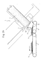
- Fig. 2a corresponds essentially 1a, b, c, the Knife edge belt conveyor 8 here by a roller conveyor is replaced, which in the illustrated embodiment only from a clockwise driven roller 17 consists.
- FIGS. 1a, b and c show just like FIGS. 1a, b and c successive operating positions of the device, and it can be seen from Figs. 2a, b that the Process of folding a product 13 with a roller conveyor can be achieved in the same way as with a Belt conveyor according to FIGS. 1a, b and c, since also by means of roller conveyor 17 shown the required acceleration forces can be applied to the product.
- the invention is not based on the illustrated embodiments limited, the funding according to the invention can ever also designed differently or arranged differently on request become.
Abstract
Description
Die Erfindung betrifft eine Vorrichtung sowie ein Verfahren zum Ablegen von scheibenförmigen, von einer Zuliefereinrichtung herabfallenden Produkten, insbesondere Lebensmittelprodukten, auf einer Abtransporteinrichtung, insbesondere einem Förderband. Weiterhin betrifft die Erfindung einen Slicer zum Aufschneiden von Lebensmittelprodukten, welcher mit einer Vorrichtung der genannten Art ausgestattet ist.The invention relates to a device and a method for storing disc-shaped, from a supplier falling products, especially food products, on a removal device, in particular one Conveyor belt. The invention further relates to a slicer for slicing food products, which with a device of the type mentioned.
Bei üblichen und bisher bekannten Vorrichtungen fallen die von der insbesondere als Aufschneideeinheit ausgebildeten Zuliefereinrichtung zur Verfügung gestellten Produktscheiben einzeln nacheinander auf ein Förderband. Durch einen Antrieb des Förderbands während des Aufschneidevorgangs kann dabei eine geschindelte Ablage der aufgeschnittenen Produkte erzielt werden. Mittels einer Unterbrechung des Aufschneidevorgangs und einem fortgesetzten Betrieb des Förderbandes und/oder einer kurzzeitigen Beschleunigung des Förderbandes während des Aufschneidevorgangs können einzelne, jeweils aus mehreren Produktscheiben bestehende Portionen auf dem Förderband voneinander getrennt werden.In conventional and previously known devices, the from the one designed in particular as a slicing unit Product slices provided by the supplier one by one on a conveyor belt. By a drive the conveyor belt during the slicing process achieved a shingled deposit of the cut products become. By interrupting the slicing process and continued operation of the conveyor belt and / or a brief acceleration of the conveyor belt During the slicing process, individual, each can be made portions of several product slices on the conveyor belt be separated from each other.
Nachteilig an den bekannten Vorrichtungen ist, daß auf die beschriebene Art und Weise lediglich eine schindelartige Ablage der Produkte erzielbar ist, wobei keinerlei weitere Möglichkeiten der Art und Weise, in welcher die Produkte abgelegt werden, gegeben sind.A disadvantage of the known devices is that on the described way only a shingle-like storage of the products is achievable, with no other options the way in which the products are filed are given.
In dem US-Patent US-A-3 855 889 ist ein Slicer mit einem Messer, einem Abtransportförderband und Mitteln, die automatisch die Faltung jeder Scheibe bewirken, beschrieben. Die Position des Abtansportförderbandes in Beziehung auf den Slicer ist einstellbar, um geschnittenes Produkt in einer gewünschten Weise aufzunehmen. Die Mittel zum automatischen Falten jeder Scheibe des geschnittenen Produkts umfassen ein Element, das in geeigneter Weise in der Bahn jeder von dem verbleibenden ungeschnittenen Produkt in Richtung auf das Förderband fallenden Scheibe angeordnet ist, um die Bahn eines Teils der Scheibe so zu beeinflussen, daß die Scheibe bei Auftreffen auf das Förderband gefaltet wird. Als Element ist ein Stab vorgesehen.In U.S. patent US-A-3 855 889 is a slicer with a knife, one Conveyor belt and means that automatically fold everyone Effect disk, described. The position of the discharge conveyor in relation to the slicer is adjustable to cut product in in a desired way. The means for automatic Folding each slice of the cut product comprise an element suitably in the path of each of the remaining uncut ones Product falling towards the conveyor belt slice is arranged to influence the path of part of the disc so that the disc is folded when it hits the conveyor belt. As an element a rod is provided.
In Patent Abstracts of Japan Vol. 18, No. 636 (M-1715), 5. Dezember 1994, ist eine Vorrichtung beschrieben, bei der durch ein horizontales Messer Scheiben von einem Produkt geschnitten werden, die auf dem Fallweg vom Messer auf ein Abförderband mit Luftströmen aus Luftdüsen beaufschlagt werden, um in gefalteter oder ausgebreiteter Form auf dem Förderband abgelegt zu werden.In Patent Abstracts of Japan Vol. 18, No. 636 (M-1715), December 5 1994, a device is described in which a horizontal Knife slices of a product that are cut on the Fall from the knife onto a conveyor belt with air flows from air nozzles to be applied to in folded or spread form on the Conveyor belt to be put down.
Eine Aufgabe der Erfindung besteht darin, eine Vorrichtung bzw. ein Verfahren der eingangs genannten Art derart weiterzubilden, daß die von der Zuliefereinrichtung herabfallenden Produkte auf verschiedene Arten abgelegt werden können. Ein Aufeinanderklappen zweier Teilbereiche der abzulegenden Produkte soll ermöglicht werden, wobei die auf diese Weise abgelegten Produkte dann wiederum schindelartig aufeinander zu liegen kommen sollen.An object of the invention is a device or to further develop a method of the type mentioned at the beginning, that falling from the supplier Products can be filed in different ways. A folding of two sections of the products to be discarded should be made possible, the on products deposited in this way are then again shingled should lie on top of each other.
Die Aufgabe wird durch eine Vorrichtung mit den Merkmalen des Auspruchs 1 gelöst.The object is achieved by a device with the features of claim 1.
Die Aufgabe wird durch ein Verfahren mit den Merkmalen des Anspruchs 8 gelöst.The object is achieved by a method having the features of
Durch das erfindungsgemäß im Bereich der Produkt-Fallinie vorgesehene Fördermittel wird der in Abtransportrichtung vorne liegende Teilbereich der herabfallenden Produkte beschleunigt. Die Beschleunigung erfolgt dabei zumindest zu Beginn des Beschleunigungsvorgangs vorzugsweise im wesentlichen in der Ebene des scheibenförmigen Produktes entgegen der Abtransportrichtung.Due to the invention in the area of the product drop line planned funding will the part of the front lying in the direction of removal falling products accelerated. The acceleration takes place at least at the beginning of the acceleration process preferably essentially in the plane of the disc-shaped Product against the direction of removal.
Dabei vollzieht der nicht beschleunigte bzw. der von dem erfindungsgemäßen Fördermittel nicht beaufschlagte Teilbereich des Produktes seine Fallbewegung weitgehend unbeeinflußt weiter, während der beschleunigte Teilbereich in einen Bereich oberhalb des nicht beschleunigten Teilbereichs bewegt wird. Durch die gleichzeitige Beschleunigung des genannten Teilbereichs und die weitgehend unbeeinflußt weiter vollzogene Fallbewegung des nicht beschleunigten Teilbereichs wird erreicht, daß der beschleunigte Teilbereich während der Fallbewegung auf den nicht beschleunigten Teilbereich des herabfallenden Produktes geklappt wird. The non-accelerated one or the one according to the invention takes place Subsidy not applied to sub-area the product continues to fall largely unaffected, during the accelerated section into an area is moved above the non-accelerated section. Due to the simultaneous acceleration of the named section and the largely unaffected continued Falling movement of the non-accelerated section is achieved that the accelerated section during the fall movement to the non-accelerated section of the falling Product is folded.
Somit fallen die von der Zuliefereinrichtung zur Verfügung gestellten Produkte mit ihren beiden aufeinandergeklappten Teilbereichen auf die Abtransporteinrichtung bzw. das Förderband, wobei bei der vorstehend erläuterten bevorzugten Ausführungsform der Erfindung der Falz der umgeklappten Produkte in Abtransportrichtung vorne zu liegen kommt.This means that they are available from the supplier products with their two folded open Partial areas on the removal device or the conveyor belt, being in the preferred embodiment explained above the invention of the fold of the folded products comes to lie at the front in the direction of removal.
Bei einer weiteren bevorzugten Ausführungsform der Erfindung wird das Fördermittel als Bandförderer ausgebildet. Dabei kann die Oberfläche des Bandförderers gegenüber der Transportfläche der Abtransporteinrichtung geringfügig geneigt sein. Typische Neigungswinkel liegen zwischen 5° und 45°, insbesondere bei ungefähr 20°.In a further preferred embodiment of the invention the funding is designed as a belt conveyor. there the surface of the belt conveyor can face the transport surface the removal device is slightly inclined his. Typical angles of inclination are between 5 ° and 45 °, especially at about 20 °.
Vorzugsweise ist der Neigungswinkel zwischen der Oberfläche
des Bandförderers und der Transportfläche der Abtransporteinrichtung
verstellbar. Die Verstellung kann dabei beispielsweise
dadurch bewirkt werden, daß die Antriebsrolle eines
Messerkanten-Bandförderers (siehe Fig. la) in ihrer Höhe verstellbar
ausgebildet ist.
Durch eine Verstellbarkeit des genannten Neigungswinkels
kann erreicht werden, daß ein herabfallendes Produkt mit seinem
gesamten, zu beschleunigenden Teilbereich auf einmal auf
die Förderfläche des Bandförderers auftrifft, was eine optimale
Übertragung der Beschleunigungskräfte sicherstellt.The angle of inclination between the surface of the belt conveyor and the transport surface of the removal device is preferably adjustable. The adjustment can be effected, for example, in that the drive roller of a knife edge belt conveyor (see FIG. 1 a) is designed to be adjustable in height.
By adjusting the angle of inclination mentioned, it can be achieved that a falling product with its entire partial area to be accelerated hits the conveyor surface of the belt conveyor at once, which ensures an optimal transmission of the acceleration forces.
Alternativ kann das Fördermittel auch als Rollenförderer mit angetriebenen Rollen ausgebildet sein. Dabei erstrecken sich die Achsen der Rollen vorzugsweise senkrecht zur Abtransportrichtung in einer im wesentlichen horizontalen Ebene.Alternatively, the funding can also be used as a roller conveyor be driven rollers. Thereby extend the axes of the rollers preferably perpendicular to the direction of removal in a substantially horizontal plane.
Die erfindungsgemäßen Fördermittel lassen sich auf besonders einfache Weise bei bestehenden Vorrichtungen zum scheibenweisen Aufschneiden von Produkten insbesondere bei Slicern zum Aufschneiden von Lebensmittelprodukten nachrüsten, da sie ohne Schwierigkeiten in dem produktabführseitig gelegenen Freiraum zwischen Schneidmesser und Abtransporteinrichtung angeordnet werden können.The funding according to the invention can be particularly simple way with existing devices for wafers Slicing of products especially with slicers for Slicing sliced food products as they retrofit without difficulty in the product discharge side Free space between the cutting knife and the removal device can be arranged.
Um eine besonders gute Übertragung der Beschleunigungskräfte von dem Fördermittel auf den jeweiligen Teilbereich des herabfallenden Produktes zu ermöglichen, können die mit den Produkten in Kontakt tretenden Bereiche des Fördermittels mit einer reibungsverstärkenden Oberfläche, insbesondere mit einer Profilierung versehen werden. Insbesondere wird dabei die Oberfläche des Förderbandes eines als Bandförderer ausgebildeten Fördermittels oder die Oberfläche der Rollen eines als Rollenförderer ausgebildeten Fördermittels mit einer Profilierung ausgestattet.For a particularly good transmission of the acceleration forces from the funding to the respective section of the to allow falling product, those with the Products contacting areas of the funding with a friction-enhancing surface, especially with be profiled. In particular, it will the surface of the conveyor belt designed as a belt conveyor Funding or the surface of the rollers of a as a roller conveyor designed funding with a profile fitted.
Bei einer bevorzugten Ausführungsform der Erfindung ist der Grad des Umklappens der herabfallenden Produkte durch die Fördergeschwindigkeit des Fördermittels und/oder durch die Position des Fördermittels im Bereich der Produkt-Fallinie einstellbar. Falls die Position des Fördermittels im Bereich der Produkt-Fallinie verstellbar ist, erfolgt diese Verstellung vorzugsweise im wesentlichen parallel zur Abtransportrichtung.In a preferred embodiment of the invention, the Degree of folding of the falling products by the Conveying speed of the funding and / or through the Position of the funding in the area of the product drop line adjustable. If the position of the funding in the area the product fall line is adjustable, this adjustment takes place preferably essentially parallel to the direction of removal.
Der Grad des Umklappens der Produkte bzw. die Größe des umgeklappten, beschleunigten Teilbereichs wird dabei umso höher, je höher die Fördergeschwindigkeit des Fördermittels bzw. je größer der mit dem Fördermittel in Kontakt tretende Teilbereich des herabfallenden Produktes ist.The degree of folding of the products or the size of the folded, accelerated section becomes all the higher the higher the conveying speed of the funding or larger the partial area coming into contact with the funding of the falling product.
Zudem ist der Grad des Umklappens auch abhängig von den Produktscheibenabmessungen und der Produktkonsistenz.In addition, the degree of folding is also dependent on the product disc dimensions and product consistency.
Der Grad der Schindelung der auf der Abtransporteinrichtung abgelegten umgeklappten Produkte kann vorzugsweise durch eine Einstellbarkeit der Transportgeschwindigkeit der Abtransporteinrichtung variabel sein.The degree of shingling on the conveyor put down folded products can preferably by an adjustability of the transport speed of the removal device be variable.
Weitere bevorzugte Ausführungsformen der Erfindung sind in den Unteransprüchen angegeben.Further preferred embodiments of the invention are in specified in the subclaims.
Die Erfindung wird nachfolgend anhand von Ausführungsbeispielen unter Bezugnahme auf die Zeichnungen beschrieben; in diesen zeigen:
- Fig. 1a, b, c
- eine schematische Seitenansicht eines mit einer erfindungsgemäßen Vorrichtung ausgestatteten Slicers mit einem als Bandförderer ausgebildeten Fördermittel in verschiedenen Betriebsstellungen und
- Fig. 2a, b
- eine schematische Seitenansicht eines mit einer erfindungsgemäßen Vorrichtung ausgestatteten Slicers mit einem als Rollenförderer ausgebildeten Fördermittel in verschiedenen Betriebsstellungen.
- 1a, b, c
- is a schematic side view of a slicer equipped with a device according to the invention with a conveyor designed as a belt conveyor in different operating positions and
- 2a, b
- is a schematic side view of a slicer equipped with a device according to the invention with a conveyor designed as a roller conveyor in different operating positions.
Fig. 1a zeigt einen Slicer 1 mit einem auf einer Planetenbahn
umlaufenden Kreismesser 2, mittels welchem ein Lebensmittelprodukt
3 aufschneidbar ist.1a shows a slicer 1 with one on a planetary orbit
revolving
Das Lebensmittelprodukt 3 ist dabei in einer Vorschubeinrichtung
4 gehalten, die eine schräg verlaufende Produktauflagefläche
5 aufweist.The
Das Kreismesser 2 erstreckt sich im wesentlichen senkrecht
zur Produktauflagefläche 5 und ist gegenüber der Horizontalen
in einem Winkel von ungefähr 45° geneigt. The
Im produktabführseitigen Freiraum des Slicers 1 ist unterhalb
des Kreismessers 2 ein erster Bereich 6 einer als Förderband
ausgebildeten Abtransporteinrichtung angeordnet, an
den sich ein ebenfalls als Förderband ausgebildeter zweiter
Bereich 7 der Abtransporteinrichtung anschließt.In the product discharge side free space of the slicer 1 is below
of the
Die Transportfläche der Abtransporteinrichtung 6, 7 erstreckt
sich dabei im wesentlichen horizontal.The transport surface of the
Der Neigungswinkel zwischen der Ebene des Kreismessers 2 und
der Transportfläche der Abtransporteinrichtung 6, 7 kann bei
Bedarf gegenüber der in Fig. 1a dargestellten Ausführungsform
auch modifiziert werden.The angle of inclination between the plane of the
Im Bereich der Produkt-Fallinie ist ein als Messerkanten-Bandförderer
8 ausgebildetes Fördermittel vorgesehen,
welches ein über eine Rolle 9 und ein Flächenelement 10 umlaufendes
Band 11 aufweist. Dabei bildet das jeweils oberhalb
des Flächenelements 10 laufende Band 11 die eigentliche
Förderfläche, welche letztendlich mit dem herabfallenden
Produkt in Kontakt tritt.In the area of the product drop line is a knife
Die Antriebsrichtung des Messerkanten-Bandförderers 8 ist
gegenläufig zur Transportrichtung der Abtransporteinrichtung
6, 7, das heißt, die Rolle 9 wird im Uhrzeigersinn angetrieben,
während die Rollen 12 der Abtransporteinrichtung 6, 7
entgegen dem Uhrzeigersinn angetrieben werden.The drive direction of the knife
Das Flächenelement 10 und somit die Transportoberfläche des
Messerkanten-Bandförderers 8 ist derart geneigt, daß der Winkel
zwischen dem Flächenelement 10 und der Transportfläche
der Abtransporteinrichtung 6, 7 ungefähr die Hälfte des Winkels
zwischen der Ebene des Kreismessers 2 und der Transportfläche
der Abtransporteinrichtung 6, 7 beträgt. The
Beim Betrieb des Slicers gemäß Fig. 1a fallen scheibenförmige
Produkte 13, die vom Kreismesser 2 vom stirnseitigen Ende
des Lebensmittelproduktes 3 abgeschnitten werden, in Richtung
des ersten Bereichs 6 der Abtransporteinrichtung. Dabei
führen diese herabfallenden Produkte 13 eine leichte Kippbewegung
in Richtung der Horizontalen aus.When operating the slicer according to FIG
Products 13 by the
Der in Abtransportrichtung vorne liegende Teilbereich des
Produktes 13 gelangt während des Fallvorgangs in Kontakt mit
dem über das Flächenelement 10 laufenden Band 11 und wird
dadurch in Förderrichtung des Bandes 11, also in Richtung
des nicht mit dem Band 11 in Kontakt tretenden Teilbereichs
des Produktes 13 beschleunigt.The part of the front lying in the direction of
Da das Produkt 13 während dieses Beschleunigungsvorgangs
weiterhin seine Fallbewegung in Richtung des ersten Bereichs
6 der Abtransporteinrichtung ausführt, nimmt das Produkt 13
im weiteren Verlauf des Fallvorgangs eine im wesentlichen
zunehmend S-förmige Gestalt an, wie dies in Fig. 1b dargestellt
ist. Man sieht in Fig. 1b, daß der vordere Teilbereich
13a in diesem Stadium in Richtung des hinteren Teilbereichs
13b gefördert und damit das Umklappen des Teilbereichs
13a auf den Teilbereich 13b eingeleitet wird.Because the
Diese Umklappbewegung wird während des weiteren Herabfallens
des Produktes 13 weiter vollzogen, wie dies aus Fig. 1c ersichtlich
ist. Der hintere, nicht beschleunigte Teilbereich
13b liegt hier bereits schindelartig auf zuvor bereits abgelegten
Produkten 14, während der vordere Teilbereich 13a
noch die restliche Klappbewegung ausführt.This flip movement will continue as it falls
of the
Nach vollzogener Klappbewegung liegt der vordere Teil 13a
unter Ausbildung eines Falzes 15 auf der Abtransporteinrichtung
6, 7. Die endgültige Form der abgelegten Produkte ist
aus den mit dem Bezugszeichen 14 versehenen Produkten ersichtlich.After the folding movement has been completed, the
Während der vordere Bereich 13a die restliche Klappbewegung
ausführt, fällt bereits das nächste Produkt 16 aus dem Bereich
des Kreismessers 2 in Richtung des Fördermittels 8,
woraufhin sich der beschriebene Vorgang wiederholt.While the
Die in Fig. 2a dargestellte Vorrichtung entspricht im wesentlichen
der Vorrichtung gemäß den Fig. 1a, b, c, wobei der
Messerkanten-Bandförderer 8 hier durch einen Rollenförderer
ersetzt ist, welcher in der dargestellten Ausführungsform
lediglich aus einer im Uhrzeigersinn angetriebenen Rolle 17
besteht.The device shown in Fig. 2a corresponds essentially
1a, b, c, the
Knife
Die Fig. 2a und 2b zeigen ebenso wie die Fig. 1a, b und c
zeitlich aufeinanderfolgende Betriebspositionen der Vorrichtung,
und es ist aus den Fig. 2a, b ersichtlich, daß der
Vorgang des Umklappens eines Produktes 13 mit einem Rollenförderer
in gleicher Weise erzielbar ist, wie mit einem
Bandförderer gemäß den Fig. 1a, b und c, da auch mittels des
dargestellten Rollenförderers 17 die erforderlichen Beschleunigungskräfte
auf das Produkt aufgebracht werden können.2a and 2b show just like FIGS. 1a, b and c
successive operating positions of the device,
and it can be seen from Figs. 2a, b that the
Process of folding a
Die Erfindung ist nicht auf die dargestellten Ausführungsbeispiele beschränkt, das erfindungsgemäße Fördermittel kann je nach Anforderung auch anders ausgebildet bzw. anders angeordnet werden. The invention is not based on the illustrated embodiments limited, the funding according to the invention can ever also designed differently or arranged differently on request become.
- 11
- Slicerslicer
- 22
- Kreismessercircular blade
- 33
- LebensmittelproduktFood product
- 44
- Vorschubeinrichtungfeeder
- 55
- Produkt-AuflageflächeProduct support surface
- 66
- Abtransporteinrichtung (erster Bereich)Removal device (first area)
- 77
- Abtransporteinrichtung (zweiter Bereich)Removal device (second area)
- 88th
- Messerkanten-BandfördererKnife-edge belt conveyor
- 99
- Rollerole
- 1010
- Flächenelementsurface element
- 1111
- Bandtape
- 1212
- Rollenroll
- 1313
- Produktproduct
- 13a13a
- vorderer Teilbereichfront section
- 13b13b
- hinterer Teilbereichrear section
- 1414
- ProdukteProducts
- 1515
- Falzfold
- 1616
- Produktproduct
- 1717
- Rollerole
Claims (10)
- An apparatus for the depositing of slice-shaped products (13, 16), in particular food products, falling from a feed device (1), comprisinga removal device (6, 7), in particular a conveyor belt, anda conveyor means (8, 17) which is driven in the opposite direction to the removal device and which is arranged in the product falling line in operation such that only the region (13a) of the falling products located at the front in the direction of removal is engaged by the conveyor means (8, 17) in order to fold the products.
- An apparatus in accordance with claim 1, characterised in that the conveyor means is formed as a belt conveyor, in particular as a knife-edge belt conveyor (8), with in particular the surface of the belt conveyor (8) being slightly inclined with respect to the transport surface of the removal device (6, 7).
- An apparatus in accordance with claim 2, characterised in that the angle of inclination amounts to between 5° and 45°, in particular to approximately 20°, and is preferably adjustable.
- An apparatus in accordance with claim 1, characterised in that the conveyor means is formed as a roller conveyor, in particular as a roller conveyor consisting of only one driven roller (17), with in particular the axis of the roller (17) extending perpendicular to the removal direction in a substantially horizontal plane.
- An apparatus in accordance with any one of the preceding claims,
characterised in that the regions (11, 17) of the conveyor means (8, 17) coming into contact with the products (13, 16) are provided with a friction-enhancing surface, in particular with a structured surface; and/or in that the conveying speed of the conveyor means (8, 17) is adjustable; and/or in that the transport speed of the removal device (6, 7) is adjustable; and/or in that the position of the conveyor means (8, 17) is adjustable in the region of the product falling line, with in particular the position of the conveyor means (8, 17) being able to be set substantially parallel to the removal direction. - An apparatus for the slice-wise cutting up of products, in particular a slicer (1) for the cutting up of food products, characterised by an apparatus in accordance with any one of the preceding claims, wherein in particular the slicer blade (2) is inclined in the direction of the conveyor means (8, 17) and wherein the slicer blade (2) and the surface of the conveyor means formed as a belt conveyor (8) preferably include an angle of less than 90 DEG, preferably less than 50 DEG, and in particular an angle of approximately 25 DEG.
- An apparatus in accordance with any one of the preceding claims,
characterised in that the transport surface of the removal device (6, 7) extends substantially horizontally. - A method for the depositing of slice-shaped products (13, 16), in particular food products, falling from a feed device (1) onto a removal device (6, 7), in particular a conveyor belt, whereinthe falling movement of the products (13, 16) is influenced by a driven conveyor means (8, 17), which acts on a region (13a) of the falling products (13, 16), andthe region (13a) acted on by the conveyor means (8, 17) is folded onto the region (13b) not acted on.
- A method in accordance with claim 8, characterised in that the falling products (13, 16) carry out a tipping movement between the feed device (1) and the conveyor means (8, 17) in the direction of the conveyor means (8, 17).
- A method in accordance with any one of claims 8 or 9,
characterised in that the region (13a) of the products (13, 16) disposed at the front in the removal direction is acted on; and/or in that the region (13a) is accelerated in the plane of the slice-shaped product (13), at least at the start of the acceleration process, with in particular the acceleration direction extending substantially opposite to the removal direction.
Applications Claiming Priority (2)
| Application Number | Priority Date | Filing Date | Title |
|---|---|---|---|
| DE19544764 | 1995-11-30 | ||
| DE19544764A DE19544764A1 (en) | 1995-11-30 | 1995-11-30 | Device and method for depositing sliced food products on a means of transport |
Publications (2)
| Publication Number | Publication Date |
|---|---|
| EP0776740A1 EP0776740A1 (en) | 1997-06-04 |
| EP0776740B1 true EP0776740B1 (en) | 2002-02-27 |
Family
ID=7778881
Family Applications (1)
| Application Number | Title | Priority Date | Filing Date |
|---|---|---|---|
| EP96119111A Expired - Lifetime EP0776740B1 (en) | 1995-11-30 | 1996-11-28 | Device and method to dispose sliced food products onto a transport means |
Country Status (6)
| Country | Link |
|---|---|
| EP (1) | EP0776740B1 (en) |
| AT (1) | ATE213690T1 (en) |
| DE (2) | DE19544764A1 (en) |
| DK (1) | DK0776740T3 (en) |
| ES (1) | ES2169198T3 (en) |
| PT (1) | PT776740E (en) |
Cited By (1)
| Publication number | Priority date | Publication date | Assignee | Title |
|---|---|---|---|---|
| EP1911555A2 (en) | 2004-02-13 | 2008-04-16 | CFS Kempten GmbH | Method and apparatus for producing portions |
Families Citing this family (11)
| Publication number | Priority date | Publication date | Assignee | Title |
|---|---|---|---|---|
| DE19735597A1 (en) * | 1997-08-15 | 1999-02-25 | Schill Maja Masch | Machine slicing meat uniformly for e.g. large catering kitchens and pre-packed meals |
| DE19820004C2 (en) * | 1998-05-06 | 2000-06-08 | Uwe Reifenhaeuser | Machine for cutting a strand of material into slices |
| DE19935055A1 (en) * | 1999-07-26 | 2001-02-01 | Biforce Anstalt Vaduz | Method and device for irregular product placement |
| DE10358069A1 (en) * | 2003-12-10 | 2005-07-14 | Cfs Kempten Gmbh | Rolled cold cuts |
| ATE385216T1 (en) * | 2004-02-13 | 2008-02-15 | Cfs Kempten Gmbh | METHOD AND DEVICE FOR PRODUCING PORTIONS |
| GB2448359A (en) * | 2007-04-13 | 2008-10-15 | Aew Delford Systems Ltd | Food Processing apparatus and operation thereof |
| DE102012112103A1 (en) | 2012-12-11 | 2014-06-12 | Gea Food Solutions Germany Gmbh | Slicing device with a folding strip |
| DE102012222914A1 (en) * | 2012-12-12 | 2014-06-12 | Weber Maschinenbau Gmbh Breidenbach | Method and apparatus for folding or turning a slice or portion of a cut food product |
| DE102013114664A1 (en) | 2013-12-20 | 2015-06-25 | Weber Maschinenbau Gmbh Breidenbach | Apparatus and method for slicing food products |
| DE102014114806A1 (en) | 2014-10-13 | 2016-04-14 | Weber Maschinenbau Gmbh Breidenbach | slicing |
| DE102017113667B4 (en) | 2017-06-21 | 2021-05-27 | Hochland Se | Slicing method and slicing device |
Family Cites Families (18)
| Publication number | Priority date | Publication date | Assignee | Title |
|---|---|---|---|---|
| DE1556704A1 (en) * | 1951-01-28 | 1970-02-19 | Winkler Duennebier Kg Masch | Device for rearranging elongated tabular parts, in particular bars made of chocolate or the like., From group-wise position on one conveyor belt to row-wise position on another conveyor belt or the like. |
| DE1216784B (en) * | 1959-11-20 | 1966-05-12 | Sig Schweiz Industrieges | Device for evenly feeding objects onto a conveyor belt |
| DD86577A1 (en) * | 1970-11-17 | 1971-12-12 | Slicer | |
| US3708055A (en) * | 1971-06-28 | 1973-01-02 | Kraftco Corp | Dispensing method and apparatus |
| NL7214451A (en) * | 1972-10-25 | 1974-04-29 | ||
| US3855889A (en) * | 1972-12-04 | 1974-12-24 | Leo S Quality Foods | Slicer |
| DE3119102A1 (en) * | 1980-05-16 | 1982-05-13 | Maatschappij van Berkel's, Patent N.V., Rotterdam | Slicing machine for foodstuffs |
| US4428263A (en) * | 1981-10-08 | 1984-01-31 | Formax, Inc. | Food loaf slicing machine |
| FR2577537A1 (en) * | 1985-02-15 | 1986-08-22 | Redoute Catalogue Sa | CONTINUOUS HANDLING METHOD AND SYSTEM FOR ITS IMPLEMENTATION |
| SE462333B (en) * | 1987-01-23 | 1990-06-11 | Moelnlycke Ab | DEVICE FOR TRANSFER OF ARTICLES FROM A FIRST TO ANOTHER TRANSPORT ROAD |
| JPS63232996A (en) * | 1987-03-20 | 1988-09-28 | 菱和株式会社 | Movable stacker in food slicing machine |
| IT1232004B (en) * | 1989-03-02 | 1992-01-22 | Hitech Systems Srl | GROUPING AND SYNCHRONIZATION EQUIPMENT OF OBJECTS FOR PACKAGING MACHINES OR BOXING MACHINES |
| GB9109866D0 (en) * | 1991-05-08 | 1991-07-03 | Thurne Eng Co Ltd | Fluffed portion preparation device |
| JP3327482B2 (en) * | 1993-02-25 | 2002-09-24 | ワタナベフーマック株式会社 | Section bending equipment for food slicers |
| DE4319171A1 (en) * | 1993-06-09 | 1994-12-15 | Dixie Union Verpackungen Gmbh | Device for shingle-like arrangement of sliced goods |
| US6022443A (en) * | 1994-01-25 | 2000-02-08 | Kimberly-Clark Worldwide, Inc. | Method and apparatus for placing discrete parts onto a moving web |
| DE4406868A1 (en) * | 1994-03-02 | 1995-09-07 | Biforce Anstalt | Method and device for forming stacks from individual slices of a food product |
| DE9421049U1 (en) * | 1994-08-18 | 1995-04-20 | Biforce Anstalt | Device for orderly depositing and transporting disc-shaped food products in portions |
-
1995
- 1995-11-30 DE DE19544764A patent/DE19544764A1/en not_active Ceased
-
1996
- 1996-11-28 DK DK96119111T patent/DK0776740T3/en active
- 1996-11-28 ES ES96119111T patent/ES2169198T3/en not_active Expired - Lifetime
- 1996-11-28 PT PT96119111T patent/PT776740E/en unknown
- 1996-11-28 EP EP96119111A patent/EP0776740B1/en not_active Expired - Lifetime
- 1996-11-28 AT AT96119111T patent/ATE213690T1/en active
- 1996-11-28 DE DE59608788T patent/DE59608788D1/en not_active Expired - Lifetime
Cited By (1)
| Publication number | Priority date | Publication date | Assignee | Title |
|---|---|---|---|---|
| EP1911555A2 (en) | 2004-02-13 | 2008-04-16 | CFS Kempten GmbH | Method and apparatus for producing portions |
Also Published As
| Publication number | Publication date |
|---|---|
| PT776740E (en) | 2002-08-30 |
| ES2169198T3 (en) | 2002-07-01 |
| ATE213690T1 (en) | 2002-03-15 |
| DE19544764A1 (en) | 1997-06-05 |
| DK0776740T3 (en) | 2002-04-22 |
| DE59608788D1 (en) | 2002-04-04 |
| EP0776740A1 (en) | 1997-06-04 |
Similar Documents
| Publication | Publication Date | Title |
|---|---|---|
| EP0776740B1 (en) | Device and method to dispose sliced food products onto a transport means | |
| EP0955137B1 (en) | Slicing machine | |
| DE1556693C3 (en) | Device for aligning a number of ampoules in a regular order | |
| DE60305523T2 (en) | APPARATUS FOR PORTIONING FOODS | |
| EP0867263B1 (en) | Product feeding system for a slicer | |
| DE3151017C2 (en) | ||
| EP3067173B1 (en) | Slicing device | |
| EP0366904B1 (en) | Method and device for packing sausages in groups side by side | |
| DE102019100631B3 (en) | sorter | |
| EP3649863B1 (en) | Lifting tipper with discharge device for compact masses of foodstuffs, in particular bar masses or biscuit doughs | |
| DE102020106054A1 (en) | Process for producing shingled portions and slicers suitable therefor | |
| WO2001007215A1 (en) | Method and device for random product placement | |
| DE4028613A1 (en) | METHOD AND DEVICE FOR FOLLOWING FOLLOWING FLAT PRODUCTS | |
| EP4281397A1 (en) | Conveyor system for conveying goods to be conveyed | |
| DE60202364T2 (en) | DEVICE AND METHOD FOR RELEASING TOBACCOBALLS | |
| DE1632102A1 (en) | Separating sheet conveyor for food processing machines | |
| DE19820269C2 (en) | Device for cutting a strand of material into slices | |
| EP3478464A1 (en) | Divided folding means | |
| EP4286117A1 (en) | Knife, cutting unit and slicing machine | |
| DE19837644B4 (en) | Apparatus and method for cutting food products | |
| DE102020110424A1 (en) | Slicing machine | |
| DE102022122170A1 (en) | Slicing machine with vacuum removal belt | |
| DE102021116847A1 (en) | slicing machine | |
| DE102019120314A1 (en) | Device for slicing food products | |
| DE60209070T2 (en) | Apparatus and method for layering tobacco bales |
Legal Events
| Date | Code | Title | Description |
|---|---|---|---|
| PUAI | Public reference made under article 153(3) epc to a published international application that has entered the european phase |
Free format text: ORIGINAL CODE: 0009012 |
|
| AK | Designated contracting states |
Kind code of ref document: A1 Designated state(s): AT BE CH DE DK ES FI FR GB GR IE IT LI LU MC NL PT SE |
|
| 17P | Request for examination filed |
Effective date: 19971128 |
|
| 17Q | First examination report despatched |
Effective date: 20001215 |
|
| GRAG | Despatch of communication of intention to grant |
Free format text: ORIGINAL CODE: EPIDOS AGRA |
|
| GRAG | Despatch of communication of intention to grant |
Free format text: ORIGINAL CODE: EPIDOS AGRA |
|
| GRAH | Despatch of communication of intention to grant a patent |
Free format text: ORIGINAL CODE: EPIDOS IGRA |
|
| GRAH | Despatch of communication of intention to grant a patent |
Free format text: ORIGINAL CODE: EPIDOS IGRA |
|
| REG | Reference to a national code |
Ref country code: GB Ref legal event code: IF02 |
|
| GRAA | (expected) grant |
Free format text: ORIGINAL CODE: 0009210 |
|
| AK | Designated contracting states |
Kind code of ref document: B1 Designated state(s): AT BE CH DE DK ES FI FR GB GR IE IT LI LU MC NL PT SE |
|
| REF | Corresponds to: |
Ref document number: 213690 Country of ref document: AT Date of ref document: 20020315 Kind code of ref document: T |
|
| REG | Reference to a national code |
Ref country code: CH Ref legal event code: EP |
|
| REF | Corresponds to: |
Ref document number: 59608788 Country of ref document: DE Date of ref document: 20020404 |
|
| REG | Reference to a national code |
Ref country code: DK Ref legal event code: T3 |
|
| GBT | Gb: translation of ep patent filed (gb section 77(6)(a)/1977) |
Effective date: 20020423 |
|
| ET | Fr: translation filed | ||
| REG | Reference to a national code |
Ref country code: ES Ref legal event code: FG2A Ref document number: 2169198 Country of ref document: ES Kind code of ref document: T3 |
|
| REG | Reference to a national code |
Ref country code: PT Ref legal event code: SC4A Free format text: AVAILABILITY OF NATIONAL TRANSLATION Effective date: 20020523 |
|
| REG | Reference to a national code |
Ref country code: GR Ref legal event code: EP Ref document number: 20020401679 Country of ref document: GR |
|
| RAP2 | Party data changed (patent owner data changed or rights of a patent transferred) |
Owner name: WEBER MASCHINENBAU GMBH & CO. KG |
|
| PG25 | Lapsed in a contracting state [announced via postgrant information from national office to epo] |
Ref country code: LU Free format text: LAPSE BECAUSE OF NON-PAYMENT OF DUE FEES Effective date: 20021128 |
|
| REG | Reference to a national code |
Ref country code: GB Ref legal event code: 732E |
|
| PLBE | No opposition filed within time limit |
Free format text: ORIGINAL CODE: 0009261 |
|
| STAA | Information on the status of an ep patent application or granted ep patent |
Free format text: STATUS: NO OPPOSITION FILED WITHIN TIME LIMIT |
|
| NLT2 | Nl: modifications (of names), taken from the european patent patent bulletin |
Owner name: WEBER MASCHINENBAU GMBH & CO. KG |
|
| REG | Reference to a national code |
Ref country code: CH Ref legal event code: PUE Owner name: WEBER MASCHINENBAU GMBH & CO. KG Free format text: BIFORCE ANSTALT#AEULESTRASSE 38#9490 VADUZ (LI) TRANSFER- WEBER MASCHINENBAU GMBH & CO. KG#FORMERSTRASSE 3#35236 BREIDENBACH (DE) |
|
| NLS | Nl: assignments of ep-patents |
Owner name: WEBER MASCHINENBAU GMBH & CO. KG |
|
| 26N | No opposition filed |
Effective date: 20021128 |
|
| REG | Reference to a national code |
Ref country code: PT Ref legal event code: PC4A Free format text: WEBER MASCHINENBAU GMBH & CO. KG DE Effective date: 20030113 |
|
| PG25 | Lapsed in a contracting state [announced via postgrant information from national office to epo] |
Ref country code: MC Free format text: LAPSE BECAUSE OF NON-PAYMENT OF DUE FEES Effective date: 20030601 |
|
| REG | Reference to a national code |
Ref country code: FR Ref legal event code: TP |
|
| PGFP | Annual fee paid to national office [announced via postgrant information from national office to epo] |
Ref country code: SE Payment date: 20041122 Year of fee payment: 9 Ref country code: PT Payment date: 20041122 Year of fee payment: 9 |
|
| PGFP | Annual fee paid to national office [announced via postgrant information from national office to epo] |
Ref country code: DK Payment date: 20041123 Year of fee payment: 9 |
|
| PGFP | Annual fee paid to national office [announced via postgrant information from national office to epo] |
Ref country code: IE Payment date: 20041124 Year of fee payment: 9 |
|
| PGFP | Annual fee paid to national office [announced via postgrant information from national office to epo] |
Ref country code: GR Payment date: 20041130 Year of fee payment: 9 |
|
| PGFP | Annual fee paid to national office [announced via postgrant information from national office to epo] |
Ref country code: BE Payment date: 20041201 Year of fee payment: 9 |
|
| PGFP | Annual fee paid to national office [announced via postgrant information from national office to epo] |
Ref country code: ES Payment date: 20041215 Year of fee payment: 9 |
|
| PGFP | Annual fee paid to national office [announced via postgrant information from national office to epo] |
Ref country code: FI Payment date: 20050221 Year of fee payment: 9 |
|
| PGFP | Annual fee paid to national office [announced via postgrant information from national office to epo] |
Ref country code: CH Payment date: 20051114 Year of fee payment: 10 |
|
| PG25 | Lapsed in a contracting state [announced via postgrant information from national office to epo] |
Ref country code: IE Free format text: LAPSE BECAUSE OF NON-PAYMENT OF DUE FEES Effective date: 20051128 Ref country code: FI Free format text: LAPSE BECAUSE OF NON-PAYMENT OF DUE FEES Effective date: 20051128 |
|
| PG25 | Lapsed in a contracting state [announced via postgrant information from national office to epo] |
Ref country code: SE Free format text: LAPSE BECAUSE OF NON-PAYMENT OF DUE FEES Effective date: 20051129 Ref country code: ES Free format text: LAPSE BECAUSE OF NON-PAYMENT OF DUE FEES Effective date: 20051129 |
|
| PG25 | Lapsed in a contracting state [announced via postgrant information from national office to epo] |
Ref country code: DK Free format text: LAPSE BECAUSE OF NON-PAYMENT OF DUE FEES Effective date: 20051130 Ref country code: BE Free format text: LAPSE BECAUSE OF NON-PAYMENT OF DUE FEES Effective date: 20051130 |
|
| PG25 | Lapsed in a contracting state [announced via postgrant information from national office to epo] |
Ref country code: PT Free format text: LAPSE BECAUSE OF NON-PAYMENT OF DUE FEES Effective date: 20060529 |
|
| REG | Reference to a national code |
Ref country code: DK Ref legal event code: EBP |
|
| EUG | Se: european patent has lapsed | ||
| REG | Reference to a national code |
Ref country code: PT Ref legal event code: MM4A Effective date: 20060529 |
|
| REG | Reference to a national code |
Ref country code: IE Ref legal event code: MM4A |
|
| PG25 | Lapsed in a contracting state [announced via postgrant information from national office to epo] |
Ref country code: LI Free format text: LAPSE BECAUSE OF NON-PAYMENT OF DUE FEES Effective date: 20061130 Ref country code: CH Free format text: LAPSE BECAUSE OF NON-PAYMENT OF DUE FEES Effective date: 20061130 |
|
| REG | Reference to a national code |
Ref country code: ES Ref legal event code: FD2A Effective date: 20051129 |
|
| REG | Reference to a national code |
Ref country code: CH Ref legal event code: PL |
|
| BERE | Be: lapsed |
Owner name: *WEBER MASCHINENBAU G.M.B.H. & CO. K.G. Effective date: 20051130 |
|
| PGFP | Annual fee paid to national office [announced via postgrant information from national office to epo] |
Ref country code: IT Payment date: 20071124 Year of fee payment: 12 |
|
| PG25 | Lapsed in a contracting state [announced via postgrant information from national office to epo] |
Ref country code: GR Free format text: LAPSE BECAUSE OF NON-PAYMENT OF DUE FEES Effective date: 20020227 |
|
| PG25 | Lapsed in a contracting state [announced via postgrant information from national office to epo] |
Ref country code: IT Free format text: LAPSE BECAUSE OF NON-PAYMENT OF DUE FEES Effective date: 20081128 |
|
| REG | Reference to a national code |
Ref country code: FR Ref legal event code: PLFP Year of fee payment: 20 |
|
| PGFP | Annual fee paid to national office [announced via postgrant information from national office to epo] |
Ref country code: GB Payment date: 20151118 Year of fee payment: 20 Ref country code: DE Payment date: 20151119 Year of fee payment: 20 |
|
| PGFP | Annual fee paid to national office [announced via postgrant information from national office to epo] |
Ref country code: AT Payment date: 20151119 Year of fee payment: 20 Ref country code: FR Payment date: 20151119 Year of fee payment: 20 Ref country code: NL Payment date: 20151118 Year of fee payment: 20 |
|
| REG | Reference to a national code |
Ref country code: DE Ref legal event code: R071 Ref document number: 59608788 Country of ref document: DE |
|
| REG | Reference to a national code |
Ref country code: NL Ref legal event code: MK Effective date: 20161127 |
|
| REG | Reference to a national code |
Ref country code: GB Ref legal event code: PE20 Expiry date: 20161127 |
|
| REG | Reference to a national code |
Ref country code: AT Ref legal event code: MK07 Ref document number: 213690 Country of ref document: AT Kind code of ref document: T Effective date: 20161128 |
|
| PG25 | Lapsed in a contracting state [announced via postgrant information from national office to epo] |
Ref country code: GB Free format text: LAPSE BECAUSE OF EXPIRATION OF PROTECTION Effective date: 20161127 |