EP0774716A1 - Sicherungseinheit - Google Patents
Sicherungseinheit Download PDFInfo
- Publication number
- EP0774716A1 EP0774716A1 EP96118255A EP96118255A EP0774716A1 EP 0774716 A1 EP0774716 A1 EP 0774716A1 EP 96118255 A EP96118255 A EP 96118255A EP 96118255 A EP96118255 A EP 96118255A EP 0774716 A1 EP0774716 A1 EP 0774716A1
- Authority
- EP
- European Patent Office
- Prior art keywords
- storage means
- hdd
- setup file
- duplication
- fault
- Prior art date
- Legal status (The legal status is an assumption and is not a legal conclusion. Google has not performed a legal analysis and makes no representation as to the accuracy of the status listed.)
- Granted
Links
Images


Classifications
-
- G—PHYSICS
- G06—COMPUTING OR CALCULATING; COUNTING
- G06F—ELECTRIC DIGITAL DATA PROCESSING
- G06F3/00—Input arrangements for transferring data to be processed into a form capable of being handled by the computer; Output arrangements for transferring data from processing unit to output unit, e.g. interface arrangements
- G06F3/06—Digital input from, or digital output to, record carriers, e.g. RAID, emulated record carriers or networked record carriers
-
- G—PHYSICS
- G06—COMPUTING OR CALCULATING; COUNTING
- G06F—ELECTRIC DIGITAL DATA PROCESSING
- G06F11/00—Error detection; Error correction; Monitoring
- G06F11/07—Responding to the occurrence of a fault, e.g. fault tolerance
- G06F11/16—Error detection or correction of the data by redundancy in hardware
- G06F11/1666—Error detection or correction of the data by redundancy in hardware where the redundant component is memory or memory area
-
- G—PHYSICS
- G06—COMPUTING OR CALCULATING; COUNTING
- G06F—ELECTRIC DIGITAL DATA PROCESSING
- G06F11/00—Error detection; Error correction; Monitoring
- G06F11/07—Responding to the occurrence of a fault, e.g. fault tolerance
- G06F11/14—Error detection or correction of the data by redundancy in operation
- G06F11/1402—Saving, restoring, recovering or retrying
- G06F11/1415—Saving, restoring, recovering or retrying at system level
- G06F11/1417—Boot up procedures
-
- G—PHYSICS
- G11—INFORMATION STORAGE
- G11C—STATIC STORES
- G11C29/00—Checking stores for correct operation ; Subsequent repair; Testing stores during standby or offline operation
- G11C29/70—Masking faults in memories by using spares or by reconfiguring
- G11C29/74—Masking faults in memories by using spares or by reconfiguring using duplex memories, i.e. using dual copies
-
- G—PHYSICS
- G06—COMPUTING OR CALCULATING; COUNTING
- G06F—ELECTRIC DIGITAL DATA PROCESSING
- G06F11/00—Error detection; Error correction; Monitoring
- G06F11/07—Responding to the occurrence of a fault, e.g. fault tolerance
- G06F11/16—Error detection or correction of the data by redundancy in hardware
- G06F11/20—Error detection or correction of the data by redundancy in hardware using active fault-masking, e.g. by switching out faulty elements or by switching in spare elements
-
- Y—GENERAL TAGGING OF NEW TECHNOLOGICAL DEVELOPMENTS; GENERAL TAGGING OF CROSS-SECTIONAL TECHNOLOGIES SPANNING OVER SEVERAL SECTIONS OF THE IPC; TECHNICAL SUBJECTS COVERED BY FORMER USPC CROSS-REFERENCE ART COLLECTIONS [XRACs] AND DIGESTS
- Y10—TECHNICAL SUBJECTS COVERED BY FORMER USPC
- Y10S—TECHNICAL SUBJECTS COVERED BY FORMER USPC CROSS-REFERENCE ART COLLECTIONS [XRACs] AND DIGESTS
- Y10S707/00—Data processing: database and file management or data structures
- Y10S707/99951—File or database maintenance
- Y10S707/99952—Coherency, e.g. same view to multiple users
- Y10S707/99953—Recoverability
-
- Y—GENERAL TAGGING OF NEW TECHNOLOGICAL DEVELOPMENTS; GENERAL TAGGING OF CROSS-SECTIONAL TECHNOLOGIES SPANNING OVER SEVERAL SECTIONS OF THE IPC; TECHNICAL SUBJECTS COVERED BY FORMER USPC CROSS-REFERENCE ART COLLECTIONS [XRACs] AND DIGESTS
- Y10—TECHNICAL SUBJECTS COVERED BY FORMER USPC
- Y10S—TECHNICAL SUBJECTS COVERED BY FORMER USPC CROSS-REFERENCE ART COLLECTIONS [XRACs] AND DIGESTS
- Y10S707/00—Data processing: database and file management or data structures
- Y10S707/99951—File or database maintenance
- Y10S707/99952—Coherency, e.g. same view to multiple users
- Y10S707/99955—Archiving or backup
Definitions
- the present invention relates to a backup unit having a countermeasure against a fault in an external storage unit, such as a hard disk drive (hereinafter referred to as HDD).
- an external storage unit such as a hard disk drive (hereinafter referred to as HDD).
- OS operating system
- HDD hard disk drive
- a duplicate of the contents of the external storage unit is usually retained in a tape unit or the like. Such a duplicate is called a backup.
- a tape unit for backup is mounted on an information processor equipped with an HDD (step S81).
- data in the HDD is copied to backup tapes (step S82).
- two backup tapes are employed, i.e., a tape to which the OS of the HDD is copied and a tape to which user's data is copied.
- the former is called an OS installation tape and the latter is called a user's data tape.
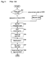
- step S91 the user checks the extent of the fault (step S91).
- the user immediately sets the OS installation tape in a tape drive unit which is mounted on the information processor (step S93).
- step S92 the user replaces the HDD with another one (step S92) and sets the OS installation tape (step S93).
- step S94 the user starts an OS installing tool from the OS installation tape (step S94), whereby the OS is installed in the HDD (step S95).
- step S96 the user resets the system of the information processor according to his work. Thereafter, the user sets the user's data tape (step S97) and restores the data from this tape into the HDD (step S98).
- Another countermeasure against the fault in the external storage unit is to duplicate the external storage unit. More specifically, two external storage units having equal performances are prepared, and data of the same contents are written in both the external storage units simultaneously. In this case, even when one of the external storage units is out of order, the user can operate the information processor continuously using the other storage unit operating normally.
- a backup unit comprises a first storage means containing at least one program and a setup file in which the operating environment of this program is written; a second storage means used when the first storage means has a fault; a duplication means for duplicating the program and the setup file contained in the first storage means, into the second storage means; and an identifier conversion means for converting identifiers included in the setup file of the first storage means and relating to the first storage means, into identifiers relating to the second storage means, when the duplication is performed. Therefore, when the operation of an information processor is stopped due to a fault in the first storage means, the second storage means enables temporary operation of the information processor.
- the second storage means a recording medium that is lower in price and writing speed than the first storage means.
- the above-mentioned backup unit further comprises a setup file managing means for judging whether at least one setup file contained in the first storage means has been updated.
- the setup file managing means judges that the setup file has been updated
- the duplication means duplicates the updated file of the first storage means, into the second storage means. Therefore, it is possible to store the latest setup file without troubling the user.
- the above-mentioned backup unit further comprises a switch means for selecting one of the first storage means and the second storage means as a storage means for booting. Therefore, when the operation of an information processor is stopped due to a fault in the first storage means, the second storage means enables temporary operation of the information processor without bothering the user with conversion of identifiers and other processes, so that the time during which the operation is stopped is reduced.
- the above-mentioned backup unit further comprises a fault detecting means for detecting a fault in the first storage means.
- the switch means selects the second storage means as a storage means for booting. Therefore, when the operation of an information processor is stopped due to a fault in the first storage means, the second storage means enables temporary operation of the information processor without troubling the user.
- the program includes at least a program of an operating system
- the setup file includes at least a setup file of the operating system
- the above-mentioned backup unit further comprises means for designating one of the first storage means and the second storage means as a source of duplication while designating the other as a target of duplication, and the duplication means duplicates the program and the setup file in the storage means designated as a source of duplication, into the storage means designated as a target of duplication. Therefore, data in the backup storage means can be restored in the other storage means. In addition, changes given to the data in the backup storage means during the temporary operation thereof are reflected in the restored data.
- Figure 1 is a block diagram illustrating an information processor employing a backup unit according to a first embodiment of the invention.
- Figure 2 is a flowchart illustrating a procedure for generating a backup using the backup unit according to the first embodiment.
- Figure 3 is a flowchart illustrating a procedure of a countermeasure against a fault in the backup unit according to the first embodiment.
- Figures 4(a) and 4(b) are tables illustrating a setup file before conversion by the backup unit according to the first embodiment and a setup file after the conversion, respectively.
- Figure 5 is a block diagram illustrating an information processor employing a backup unit according to a second embodiment of the invention.
- Figure 6 is a flowchart illustrating a procedure for generating a backup using the backup unit according to the second embodiment.
- Figure 7 is a flowchart illustrating a procedure for detecting a fault in the backup unit according to the second embodiment when the information processor is started.
- Figure 8 is a flowchart illustrating a procedure of a countermeasure against a fault in the backup unit according to the second embodiment.
- Figure 9 is a flowchart illustrating a procedure for updating backup data by the backup unit according to the second embodiment.
- Figure 10 is a flowchart illustrating a procedure for generating a backup using a conventional backup unit.
- Figure 11 is a flowchart illustrating a procedure of a countermeasure against a fault in the conventional backup unit.
- Figure 1 is a block diagram illustrating an information processor employing a backup unit according to a first embodiment of the invention.
- the backup unit comprises a first HDD 10 serving as a storage means when the information processor operates normally, a second HDD 20 serving as a storage means when the first HDD 10 is out of order, a central control unit 30 for instructing duplication of data and other processes, and an internal memory unit 50.
- the first HDD 10 contains an OS 11 and a setup file 12 on the basis of the OS 11.
- the second HDD 20 contains an OS 21 which is a duplicate of the OS 11, a setup file 22 which is a duplicate of the setup file 12, and a setup file 23 which is obtained by converting the setup file 12.
- the central control unit 30 comprises a duplication and conversion unit 31 for duplication of data, conversion of data, and other processes, and a system loading switch unit 32 for selecting one of the HDD 10 and the HDD 20 as a storage unit for booting (i.e., starting).
- the first HDD 10, the second HDD 20, the central control unit 30, and the internal memory unit 50 are connected with each other through an internal bus 60 and an external bus 70.
- Figure 2 is a flowchart showing a procedure for generating a backup using the backup unit according to the first embodiment.
- Figure 3 is a flowchart showing a procedure of a countermeasure adopted by the user when the HDD 10 has a fault.
- Figure 4(a) shows an example of a setup file 12 before it is converted by the backup unit, and figure 4(b) shows an example of a setup file 23 after conversion.
- the user instructs the duplication and conversion unit 31 to duplicate and convert the contents of the first HDD 10.
- the duplication and conversion unit 31 duplicates the OS 11 to generate the OS 21 (step S11) and duplicates the setup file 12 to generate the setup file 22 (step S12).
- the HDD 10 contains user's data
- this data is also duplicated and stored in the HDD 20 (step S13).
- the duplication and conversion unit 31 converts a portion of data in the setup file 22 in the HDD 20, which portion is coded in device identifiers of the HDD 10, into data coded in device identifiers of the HDD 20, thereby generating the setup file 23 (step S14). After the conversion, the duplication and conversion unit 31 stores the setup file 23 in the HDD 20 to complete the backup.
- the setup file 12 includes device identifiers of the third storage unit, but these device identifiers are not converted.
- the user changes the target of OS loading from the first HDD 10 to the second HDD 20 by the system loading switch unit 32 (step S21), and the user loads the OS 21 and the setup file 23 to boot the system from the second HDD 20 (step S22). Then, the user decides whether the HDD 10 should be recovered or not (step S23). When the decision is not to recover the HDD 10, the user operates the information processor temporarily using the second HDD until an HDD for replacement is prepared.
- step S24 the user judges the extent of the fault in the HDD 10 (step S24).
- step S30 the user operates the information processor temporarily using the second HDD until an HDD for replacement is prepared.
- step S31 the user stops the operation of the system (step S31) and replaces the first HDD 10 with the new HDD (step S32). Then, the user returns to step S21.
- the user designates the second HDD 20 as a source of duplication and conversion and the first HDD 10 as a target of duplication and conversion. Then the user instructs the duplication and conversion unit 31 to duplicate the contents of the second HDD 20 into the first HDD 10.
- the duplication and conversion unit 31 duplicates the OS 21 to generate the OS 11 (step S25) and duplicates the setup file 22 to generate the setup file 12 (step S26).
- the HDD 20 contains user's data
- this data is also duplicated and stored in the HDD 10 (step S27).
- the target of OS loading is returned to the first HDD 10 by the system loading switch unit 32 (step S28).
- the HDD 10 (first storage means) contains at least one program and a setup file in which an operating environment of this program is written.
- the duplication and conversion unit 31 duplicates the program and the setup file of the first HDD 10 into the second HDD 20 (second storage means).
- the setup file is duplicated, if the setup file includes identifiers relating to the first HDD 10, the duplication and conversion unit 31 (identifier conversion means) converts these identifiers to identifiers relating to the second HDD 20.
- the system loading switch unit 32 selects the second HDD 20 as a storage unit for booting and boots the system from the second HDD 20. Therefore, it is possible for the user to operate the information processor temporarily, so that the inoperable time of the information processor can be reduced.
- the duplication and conversion unit 31 designates the second HDD 20 as a source of duplication and the first HDD 10 as a target of duplication, and duplicates the contents of the second HDD 20 into the first HDD 10. Therefore, the contents of the backup storage unit can be restored into the other storage unit. In addition, any changes to the data in the backup storage unit which has been temporarily operated will be reflected in the restored data.
- Figure 5 is a block diagram illustrating an information processor employing a backup unit according to a second embodiment of the present invention.
- the backup unit comprises an HDD 10 serving as a first storage means when the information processor operates normally, a rewritable optical disk 40 serving as a second storage means when the first HDD 10 is out of order, a central control unit 30 for instructing duplication of data and other processes, and an internal memory unit 50.
- the HDD 10 contains an OS 11 and a setup file 12 on the basis of the OS 11.
- the optical disk 40 contains an OS 41 which is a duplicate of the OS 11 and a setup file 42 which is a duplicate of the setup file 12.
- the central control unit 30 comprises a duplication and conversion unit 31 for duplication of data, conversion of data, and other processes, a system loading switch unit 32 for selecting one of the HDD 10 and the optical disk 40 as a storage unit for booting, a setup file correction detector 33, and an HDD fault detector 34.
- the HDD 10, the optical disk 40, the central control unit 30, and the internal memory unit 50 are connected with each other through an internal bus 60 and an external bus 70.
- FIG. 6 is a flowchart showing a procedure for generating a backup using the backup unit according to the second embodiment.
- Figure 7 is a flowchart showing the operation of the HDD fault detector 34 when the information processor is started.
- Figure 8 is a flowchart showing a procedure of a countermeasure against HDD fault.
- Figure 9 is a flowchart showing a procedure for updating a backup.
- the user mounts the rewritable optical disk 40 as a second storage means (step S41) and instructs the duplication and conversion unit 31 to duplicate and convert the contents of the HDD 10.
- the duplication and conversion unit 31 duplicates the OS 11 to generate an OS 41 (step S42).
- the unit 31 generates a setup file 42 by converting a portion of data in the setup file 12, which portion is coded in device identifiers of the HDD 10, into data coded in device identifiers of the optical disk 40, and stores the setup file 42 in the optical disk 40 (step S43).
- duplication of the setup file 12 is not performed.
- the HDD 10 contains user's data, this data is also duplicated and stored in the optical disk 40 (step S44).
- the HDD fault detector 34 judges whether the HDD 10 has a fault or not by detecting, for example, "reading or writing error" of the HDD 10 or "access time out” to the HDD 10 (step S45). When the HDD 10 has no fault, the information processor is started by the HDD 10 (step S47). On the other hand, when the HDD 10 has a fault, the HDD fault detector 34 instructs the system loading switch unit 32 to change the target of OS loading from the HDD 10 to the optical disk 40 (step S46). The system loading switch unit 32 loads the OS 41 and the setup file 42 to boot the system from the optical disk 40 (step S48). Thereafter, the information processor is operated temporarily by the optical disk 40 until the HDD 10 is replaced with another HDD.
- the user changes the target of OS loading from the HDD 10 to the optical disk 40 by the system loading switch unit 32 (step S61), and the user loads the OS 41 and the setup file 42 to boot the system from the optical disk 40 (step S62). Then, the user decides whether the HDD 10 should be recovered or not (step S63). When the decision is not to recover the HDD 10, the user operates the information processor temporarily using the optical disk 40 until an HDD for replacement is prepared.
- step S64 the user judges the extent of the fault (step S64).
- step S69 the user operates the information processor temporarily using the optical disk 40 until an HDD for replacement is prepared. If an HDD for replacement is available, the user stops the operation of the system (step S70) and replaces the HDD 10 with the new HDD (step S71). Then, the user returns to step S61.
- the user designates the optical disk 40 as a source of duplication and conversion and the HDD 10 as a target of duplication and conversion. Then, the user instructs the duplication and conversion unit 31 to duplicate and convert the contents of the optical disk 40 into the HDD 10.
- the duplication and conversion unit 31 duplicates the OS 41 to generate the OS 11 (step S65) and duplicates the setup file 42 to generate the setup file 12 (step S66).
- the duplication and conversion unit 31 converts a portion of data in the setup file 12, which portion is coded in device identifiers of the optical disk 40, into data coded in device identifiers of the HDD 10 (step S67).
- the system loading switch unit 32 returns the target of OS loading to the HDD 10 (step S68).
- the setup file correction detector 33 detects the correction of the setup file 12 by, for example, comparing the change time of the setup file 12 with the generation time of the setup file 42 (step S51).
- the duplication and conversion unit 31 duplicates the setup file 12 in the HDD 10 into the setup file 42 in the optical disk 40 while converting identifiers relating to the HDD to identifiers relating to the optical disk (step S52), whereby the setup file 42 is updated.
- the setup file 12 is not updated.
- the HDD 10 (first storage means) contains at least one program and a setup file in which an operating environment of this program is written.
- the duplication and conversion unit 31 duplicates the program and the setup file of the HDD 10 into the optical disk 40 (second storage means).
- the setup file includes identifiers relating to the HDD 10
- the duplication and conversion unit 31 (identifier conversion means) converts these identifiers to identifiers relating to the optical disk 40. Therefore, it is possible to employ, as the second storage means, a recording medium that is lower in price and writing speed than the first storage means.
- the HDD fault detector 34 fault detecting means
- the system loading switch unit 32 switch means
- the setup file correction detector 33 (setup file managing means) checks whether or not the setup file in the HDD 10 is updated and, when it is updated, the updated file is duplicated in the optical disk 40. Therefore, it is possible to store the setup file 42 corresponding to the latest setup file 12, without troubling the user.
- the user restores the HDD 10 using the system of the optical disk 40, which system is booted for the temporary operation, since changes given to the setup file 42 by the user during the temporary operation are reflected in the setup file 12 as latest data, the HDD 10 can be regenerated with no necessity of changing the setup file 12.
- the backup unit of the present invention is not restricted to those described for the first and second embodiments. Although in the first and second embodiments an HDD or an optical disk is used as the second external storage unit, a floppy disk or a rewritable ROM, such as an EEPROM or a flash ROM, may be used with the same effects as mentioned above.
- the duplication and conversion unit 31, the system loading switch unit 32, the setup file correction detector 33, and the HDD fault detector 34 are implemented by software, i.e., programs loaded to the central control unit 30.
- these constituents may be implemented by hardware. Further, when these constituents are implemented by software, their programs may be stored in the HDD 10.
- a program for generating the system loading switch unit 32 may be stored in a ROM in the information processor.
Landscapes
- Engineering & Computer Science (AREA)
- Theoretical Computer Science (AREA)
- Physics & Mathematics (AREA)
- General Engineering & Computer Science (AREA)
- General Physics & Mathematics (AREA)
- Quality & Reliability (AREA)
- Human Computer Interaction (AREA)
- Information Retrieval, Db Structures And Fs Structures Therefor (AREA)
- Techniques For Improving Reliability Of Storages (AREA)
Applications Claiming Priority (3)
| Application Number | Priority Date | Filing Date | Title |
|---|---|---|---|
| JP29583295 | 1995-11-14 | ||
| JP295832/95 | 1995-11-14 | ||
| JP29583295 | 1995-11-14 |
Publications (2)
| Publication Number | Publication Date |
|---|---|
| EP0774716A1 true EP0774716A1 (de) | 1997-05-21 |
| EP0774716B1 EP0774716B1 (de) | 2003-03-05 |
Family
ID=17825767
Family Applications (1)
| Application Number | Title | Priority Date | Filing Date |
|---|---|---|---|
| EP96118255A Expired - Lifetime EP0774716B1 (de) | 1995-11-14 | 1996-11-14 | Sicherungseinheit |
Country Status (4)
| Country | Link |
|---|---|
| US (1) | US5860122A (de) |
| EP (1) | EP0774716B1 (de) |
| KR (1) | KR100244838B1 (de) |
| DE (1) | DE69626463T2 (de) |
Cited By (3)
| Publication number | Priority date | Publication date | Assignee | Title |
|---|---|---|---|---|
| EP1630659A2 (de) | 2004-08-25 | 2006-03-01 | Aruze Corp. | Informationsverarbeitungsvorrichtung |
| EP1758024A3 (de) * | 2005-08-26 | 2007-12-05 | Fujitsu Limited | Informationsverarbeitungsvorrichtung, Steuerprogramm für eine Informationsverarbeitungsvorrichtung und Steuerverfahren für eine Informationsverarbeitungsvorrichtung |
| EP1879109A4 (de) * | 2005-03-29 | 2009-07-29 | Fujitsu Ltd | Informationsverarbeitungseinrichtung, programm und speichermedium |
Families Citing this family (11)
| Publication number | Priority date | Publication date | Assignee | Title |
|---|---|---|---|---|
| JPH10333948A (ja) * | 1997-04-01 | 1998-12-18 | Kokusai Zunou Sangyo Kk | 仮想データベース空間システムおよびデータベースプログラムを記録したコンピュータ読み取り可能な記録媒体 |
| US6003044A (en) * | 1997-10-31 | 1999-12-14 | Oracle Corporation | Method and apparatus for efficiently backing up files using multiple computer systems |
| US6205527B1 (en) * | 1998-02-24 | 2001-03-20 | Adaptec, Inc. | Intelligent backup and restoring system and method for implementing the same |
| US6728896B1 (en) * | 2000-08-31 | 2004-04-27 | Unisys Corporation | Failover method of a simulated operating system in a clustered computing environment |
| US6611902B2 (en) * | 2000-11-13 | 2003-08-26 | Matsushita Electric Industrial Co., Ltd. | Information processor and information processing method |
| JP4512386B2 (ja) * | 2004-03-05 | 2010-07-28 | 株式会社日立製作所 | バックアップシステムおよび方法 |
| US20060055796A1 (en) * | 2004-09-16 | 2006-03-16 | Kabushiki Kaisha Toshiba | Image processing apparatus |
| JP4596889B2 (ja) | 2004-11-08 | 2010-12-15 | 株式会社日立製作所 | ストレージシステムの管理方法 |
| JP4671332B2 (ja) * | 2005-03-10 | 2011-04-13 | 株式会社日立製作所 | ユーザ識別情報を変換するファイルサーバ |
| JP4339843B2 (ja) * | 2005-11-21 | 2009-10-07 | シャープ株式会社 | データ処理装置 |
| JP2019049907A (ja) * | 2017-09-11 | 2019-03-28 | キヤノン株式会社 | 情報処理装置、情報処理方法及びプログラム |
Citations (1)
| Publication number | Priority date | Publication date | Assignee | Title |
|---|---|---|---|---|
| EP0586907A1 (de) * | 1992-09-02 | 1994-03-16 | MAN Roland Druckmaschinen AG | Rechner für den Leitstand einer Maschine, insbesondere einer Druckmaschine |
Family Cites Families (6)
| Publication number | Priority date | Publication date | Assignee | Title |
|---|---|---|---|---|
| EP0483865A3 (en) * | 1990-11-02 | 1992-09-02 | Kabushiki Kaisha Toshiba | Personal computer capable of changing boot priority |
| US5519969A (en) * | 1991-08-19 | 1996-05-28 | Golba; Thomas R. | Removable roof flashing cover system |
| US5327531A (en) * | 1992-09-21 | 1994-07-05 | International Business Machines Corp. | Data processing system including corrupt flash ROM recovery |
| US5469573A (en) * | 1993-02-26 | 1995-11-21 | Sytron Corporation | Disk operating system backup and recovery system |
| JP2872008B2 (ja) * | 1993-08-19 | 1999-03-17 | 日本電気株式会社 | コンピュータシステムおよびそのシステム縮退運転実現方法 |
| US5754848A (en) * | 1996-09-11 | 1998-05-19 | Hewlett-Packard Co. | Apparatus and method for disaster recovery of an operating system utilizing long file and directory names |
-
1996
- 1996-11-12 US US08/747,601 patent/US5860122A/en not_active Expired - Fee Related
- 1996-11-14 KR KR1019960053980A patent/KR100244838B1/ko not_active Expired - Fee Related
- 1996-11-14 EP EP96118255A patent/EP0774716B1/de not_active Expired - Lifetime
- 1996-11-14 DE DE69626463T patent/DE69626463T2/de not_active Expired - Fee Related
Patent Citations (1)
| Publication number | Priority date | Publication date | Assignee | Title |
|---|---|---|---|---|
| EP0586907A1 (de) * | 1992-09-02 | 1994-03-16 | MAN Roland Druckmaschinen AG | Rechner für den Leitstand einer Maschine, insbesondere einer Druckmaschine |
Non-Patent Citations (3)
| Title |
|---|
| "AUTOMATIC IPL DRIVE SWITCH", IBM TECHNICAL DISCLOSURE BULLETIN, vol. 37, no. 7, 1 July 1994 (1994-07-01), pages 5/6, XP000455419 * |
| "INITIAL MICROCODE LOAD OVERLAY EXECUTION FOR PERSONAL COMPUTERS", IBM TECHNICAL DISCLOSURE BULLETIN, vol. 37, no. 10, 1 October 1994 (1994-10-01), pages 5 - 8, XP000475557 * |
| "METHOD TO RECOVER FROM FAILED BOOT DRIVE USING DISKETTES", IBM TECHNICAL DISCLOSURE BULLETIN, vol. 36, no. 10, 1 October 1993 (1993-10-01), pages 329/330, XP000412279 * |
Cited By (7)
| Publication number | Priority date | Publication date | Assignee | Title |
|---|---|---|---|---|
| EP1630659A2 (de) | 2004-08-25 | 2006-03-01 | Aruze Corp. | Informationsverarbeitungsvorrichtung |
| EP1630659A3 (de) * | 2004-08-25 | 2008-01-23 | Aruze Corp. | Informationsverarbeitungsvorrichtung |
| US7664988B2 (en) | 2004-08-25 | 2010-02-16 | Universal Entertainment Corporation | Gaming apparatus having memory fault detection |
| US8112670B2 (en) | 2004-08-25 | 2012-02-07 | Universal Entertainment Corporation | Gaming apparatus having memory fault detection |
| EP1879109A4 (de) * | 2005-03-29 | 2009-07-29 | Fujitsu Ltd | Informationsverarbeitungseinrichtung, programm und speichermedium |
| EP1758024A3 (de) * | 2005-08-26 | 2007-12-05 | Fujitsu Limited | Informationsverarbeitungsvorrichtung, Steuerprogramm für eine Informationsverarbeitungsvorrichtung und Steuerverfahren für eine Informationsverarbeitungsvorrichtung |
| US7631216B2 (en) | 2005-08-26 | 2009-12-08 | Fujitsu Limited | Information processing apparatus, information processing apparatus control program, and information processing apparatus control method |
Also Published As
| Publication number | Publication date |
|---|---|
| US5860122A (en) | 1999-01-12 |
| KR970028983A (ko) | 1997-06-26 |
| EP0774716B1 (de) | 2003-03-05 |
| KR100244838B1 (ko) | 2000-02-15 |
| DE69626463T2 (de) | 2004-02-26 |
| DE69626463D1 (de) | 2003-04-10 |
Similar Documents
| Publication | Publication Date | Title |
|---|---|---|
| US5860122A (en) | Backup unit including identifier conversion means | |
| US6073220A (en) | Apparatus and method for providing a transparent disk drive back-up | |
| US6253281B1 (en) | Method for updating firmware of a computer peripheral device | |
| US6820214B1 (en) | Automated system recovery via backup and restoration of system state | |
| US6851073B1 (en) | Extensible system recovery architecture | |
| CA2323106C (en) | File server storage arrangement | |
| US20020078338A1 (en) | Method and apparatus for fast computer initialization | |
| US7000231B1 (en) | Method of manufacturing operating system master template, method of manufacturing a computer entity and product resulting therefrom, and method of producing a production version of an operating system | |
| US20030105922A1 (en) | Disk array apparatus and parity processing method therein | |
| WO2000020971A1 (en) | Recovery of file systems after modification failure | |
| GB2234373A (en) | Storage back-up system | |
| JP2009151826A (ja) | コンピュータメモリ装置のための変更可能な区画ブート記録 | |
| EP0483174B1 (de) | Verfahren zum betrieb eines datenverarbeitungssystems | |
| US20040236907A1 (en) | Method and apparatus for managing computer storage devices for improved operational availability | |
| US20040215952A1 (en) | Apparatus, method and recording medium for starting up data processing system | |
| CA2071346A1 (en) | Method and means for time zero backup copy of data | |
| US6023584A (en) | Installation of computer programs using disk mirroring | |
| US20050262033A1 (en) | Data recording apparatus, data recording method, program for implementing the method, and program recording medium | |
| JP3048792B2 (ja) | オペレーティングシステムの自動入れ替え方法及びそれを利用した計算機システム | |
| JP3178817B2 (ja) | マルチモジュールマシンにおける重要データの管理のためのアーキテクチャにおけるデータの管理方法 | |
| CN116361817A (zh) | 一种Linux下ubi文件系统的保护方法 | |
| JPH09198290A (ja) | バックアップ装置 | |
| JP4358943B2 (ja) | 自動バックアップシステム及び自動バックアッププログラムを記録した記録媒体 | |
| JP3463696B2 (ja) | オンラインガーベッジコレクション処理方法 | |
| JPH05313973A (ja) | 外部記憶装置のバックアップ方式 |
Legal Events
| Date | Code | Title | Description |
|---|---|---|---|
| PUAI | Public reference made under article 153(3) epc to a published international application that has entered the european phase |
Free format text: ORIGINAL CODE: 0009012 |
|
| AK | Designated contracting states |
Kind code of ref document: A1 Designated state(s): DE FR GB |
|
| 17P | Request for examination filed |
Effective date: 19970620 |
|
| 17Q | First examination report despatched |
Effective date: 20010919 |
|
| GRAG | Despatch of communication of intention to grant |
Free format text: ORIGINAL CODE: EPIDOS AGRA |
|
| GRAG | Despatch of communication of intention to grant |
Free format text: ORIGINAL CODE: EPIDOS AGRA |
|
| GRAH | Despatch of communication of intention to grant a patent |
Free format text: ORIGINAL CODE: EPIDOS IGRA |
|
| GRAH | Despatch of communication of intention to grant a patent |
Free format text: ORIGINAL CODE: EPIDOS IGRA |
|
| GRAA | (expected) grant |
Free format text: ORIGINAL CODE: 0009210 |
|
| AK | Designated contracting states |
Designated state(s): DE FR GB |
|
| REG | Reference to a national code |
Ref country code: GB Ref legal event code: FG4D |
|
| REF | Corresponds to: |
Ref document number: 69626463 Country of ref document: DE Date of ref document: 20030410 Kind code of ref document: P |
|
| ET | Fr: translation filed | ||
| PLBE | No opposition filed within time limit |
Free format text: ORIGINAL CODE: 0009261 |
|
| STAA | Information on the status of an ep patent application or granted ep patent |
Free format text: STATUS: NO OPPOSITION FILED WITHIN TIME LIMIT |
|
| 26N | No opposition filed |
Effective date: 20031208 |
|
| PGFP | Annual fee paid to national office [announced via postgrant information from national office to epo] |
Ref country code: GB Payment date: 20061108 Year of fee payment: 11 Ref country code: FR Payment date: 20061108 Year of fee payment: 11 |
|
| PGFP | Annual fee paid to national office [announced via postgrant information from national office to epo] |
Ref country code: DE Payment date: 20061109 Year of fee payment: 11 |
|
| GBPC | Gb: european patent ceased through non-payment of renewal fee |
Effective date: 20071114 |
|
| PG25 | Lapsed in a contracting state [announced via postgrant information from national office to epo] |
Ref country code: DE Free format text: LAPSE BECAUSE OF NON-PAYMENT OF DUE FEES Effective date: 20080603 |
|
| REG | Reference to a national code |
Ref country code: FR Ref legal event code: ST Effective date: 20080930 |
|
| PG25 | Lapsed in a contracting state [announced via postgrant information from national office to epo] |
Ref country code: GB Free format text: LAPSE BECAUSE OF NON-PAYMENT OF DUE FEES Effective date: 20071114 |
|
| PG25 | Lapsed in a contracting state [announced via postgrant information from national office to epo] |
Ref country code: FR Free format text: LAPSE BECAUSE OF NON-PAYMENT OF DUE FEES Effective date: 20071130 |