EP0774635A1 - Four à cuve annulaire - Google Patents
Four à cuve annulaire Download PDFInfo
- Publication number
- EP0774635A1 EP0774635A1 EP96115275A EP96115275A EP0774635A1 EP 0774635 A1 EP0774635 A1 EP 0774635A1 EP 96115275 A EP96115275 A EP 96115275A EP 96115275 A EP96115275 A EP 96115275A EP 0774635 A1 EP0774635 A1 EP 0774635A1
- Authority
- EP
- European Patent Office
- Prior art keywords
- furnace
- inner cylinder
- hot gas
- annular space
- level
- Prior art date
- Legal status (The legal status is an assumption and is not a legal conclusion. Google has not performed a legal analysis and makes no representation as to the accuracy of the status listed.)
- Granted
Links
- 239000000463 material Substances 0.000 claims abstract description 24
- 238000001816 cooling Methods 0.000 claims abstract description 13
- 235000008733 Citrus aurantifolia Nutrition 0.000 claims abstract description 5
- 235000011941 Tilia x europaea Nutrition 0.000 claims abstract description 5
- 239000004571 lime Substances 0.000 claims abstract description 5
- 239000010459 dolomite Substances 0.000 claims abstract description 4
- 229910000514 dolomite Inorganic materials 0.000 claims abstract description 4
- 235000019738 Limestone Nutrition 0.000 claims abstract description 3
- 239000006028 limestone Substances 0.000 claims abstract description 3
- 239000007789 gas Substances 0.000 claims description 34
- 238000006243 chemical reaction Methods 0.000 claims description 3
- 238000002485 combustion reaction Methods 0.000 claims description 2
- 239000011435 rock Substances 0.000 claims description 2
- 238000007669 thermal treatment Methods 0.000 claims description 2
- 238000010304 firing Methods 0.000 abstract description 8
- 238000007599 discharging Methods 0.000 abstract 1
- 210000001035 gastrointestinal tract Anatomy 0.000 description 6
- 230000000694 effects Effects 0.000 description 3
- 238000000605 extraction Methods 0.000 description 2
- 238000000034 method Methods 0.000 description 2
- 230000001105 regulatory effect Effects 0.000 description 2
- 206010006784 Burning sensation Diseases 0.000 description 1
- 230000007613 environmental effect Effects 0.000 description 1
- 239000000446 fuel Substances 0.000 description 1
- 239000007788 liquid Substances 0.000 description 1
- 238000012423 maintenance Methods 0.000 description 1
- 238000004519 manufacturing process Methods 0.000 description 1
- 239000004575 stone Substances 0.000 description 1
- 239000000126 substance Substances 0.000 description 1
Images

Classifications
-
- F—MECHANICAL ENGINEERING; LIGHTING; HEATING; WEAPONS; BLASTING
- F27—FURNACES; KILNS; OVENS; RETORTS
- F27B—FURNACES, KILNS, OVENS OR RETORTS IN GENERAL; OPEN SINTERING OR LIKE APPARATUS
- F27B1/00—Shaft or like vertical or substantially vertical furnaces
- F27B1/005—Shaft or like vertical or substantially vertical furnaces wherein no smelting of the charge occurs, e.g. calcining or sintering furnaces
-
- C—CHEMISTRY; METALLURGY
- C04—CEMENTS; CONCRETE; ARTIFICIAL STONE; CERAMICS; REFRACTORIES
- C04B—LIME, MAGNESIA; SLAG; CEMENTS; COMPOSITIONS THEREOF, e.g. MORTARS, CONCRETE OR LIKE BUILDING MATERIALS; ARTIFICIAL STONE; CERAMICS; REFRACTORIES; TREATMENT OF NATURAL STONE
- C04B2/00—Lime, magnesia or dolomite
- C04B2/10—Preheating, burning calcining or cooling
- C04B2/12—Preheating, burning calcining or cooling in shaft or vertical furnaces
Definitions
- the invention relates to a ring shaft furnace for the treatment of lumpy material, in particular for the thermal treatment of lime and dolomite rock for conversion into lime, with the features in the preamble of claim 1, as are known from DE 3 915 986 C1.
- a ring shaft furnace consists of a cylindrical outer jacket with an essentially vertical axis, in which one or more inner cylinders are concentrically arranged over part of its length to form an annular space.
- a lock with a feed hopper for loading lumpy goods.
- the lock is intended to prevent gases from entering or escaping in an uncontrolled manner when the furnace is loaded with lumpy material.
- a discharge device that discharges the material converted by firing.
- the lumpy material located in the annular space of the shaft furnace slides down and thus gradually reaches the top discharge end of the furnace to its lower discharge end.
- the chemical conversion takes place with the aid of hot gases which enter the furnace and flow through the furnace from bottom to top through the lumpy material.
- the connecting pieces are offset from one another such that a connecting piece of the level below is arranged in the middle between two connecting pieces of the upper level. In this way, the uniform introduction of the burner gases into the annular pillar is ensured.
- the preheating zone and the first firing zone are located at the top end of the ring shaft furnace up to the uppermost cross-sectional plane, in which hot gas supply nozzles are arranged, from top to bottom.
- the middle firing zone is located between the uppermost and the next lower feed neck level, and the lower firing zone is formed between the middle to the lower level of the feed neck.
- the cooling zone is located from the lowest level of the feed pipe to the lower end of the shaft furnace.
- the gases in the upper part of the furnace are sucked out of the furnace by means of a suction blower and / or forced through the furnace by means of a pressure blower. If a suction fan is arranged, a negative pressure is created in the furnace compared to the surrounding atmosphere. This has the advantage that one does not have to reckon with the escape of pressurized gases from the furnace at any point when opening the furnace. If necessary, maintenance work can be carried out while the furnace is in operation.
- Cooling air can enter the cooling zone through the discharge openings in the lower part of the ring shaft furnace.
- the cooling effect can be regulated by the outside air by centrally extracting this cooling air from the cooling zone.
- the furnace can also be equipped with various auxiliary devices, such as heat exchangers, circulation devices and the like, but these are of no further interest here in connection with the invention.
- the known ring shaft furnace described above is intended and suitable for burning lumpy material in various degrees of hardness.
- more or less hard-burned lime from limestone or dolomite stone can be produced through the graded and regulated firing process.
- the invention is based on the object of creating a ring shaft furnace which is suitable both for burning lumpy material in various degrees of hardness and also for producing soft-burned, highly reactive material. So far, such a ring shaft furnace has not been considered in the conception, nor has it been implemented in practice.
- the solution according to the invention consists in that the annular shaft furnace has hot gas supply nozzles in its central part in at least three spaced cross-sectional zones and gas extraction through the inner cylinder, the openings for the extraction from the annular space being approximately at the level of the lowest hot gas Feed pipe level are located.
- These openings for the hot gas suction are preferred arranged in a cross-sectional plane distributed around the circumference of the inner cylinder in order to suck the hot gases evenly out of the annular space.
- a suction line is connected to the inner cylinder, which leads to a vacuum generating unit, e.g. B. can lead a suction fan outside the oven.
- a vacuum generating unit e.g. B. a suction fan may be arranged. In the latter case, the accessibility to the fan, for example when a repair is necessary, is of course difficult.
- the hot gases drawn off by the inner cylinder can either be fed to a heat exchanger or / and they are fed to the central hot gas feed pipe, so that they are circulated and thus cause no environmental problems and guarantee the greatest possible heat utilization.
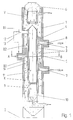
- the ring shaft furnace has a cylindrical casing 1, which is supported on the floor 2 with an approximately vertical axis.
- the inner cylinder 3 is arranged concentrically in it and connected to the jacket 1 via bridges 4.
- the lumpy material 6 is located in the annular space 5 between the jacket 1 and the inner cylinder 3 End of the furnace abandoned and discharged at its lower end after passing through the furnace.
- nozzles 7 are uniformly distributed over the furnace circumference for the supply of hot gases.
- the hot gases can be generated by burners or supplied from other sources.
- the nozzles 7 open in each level under a bridge 4, where a cavity 8 not occupied with lumpy material 6 is formed, from which the gases are distributed into the annular space 5 and flow upwards in the direction of the arrow.
- three nozzles 7 are provided in a cross-sectional plane, the axes of which each enclose an angle of 120 °.
- the nozzles 7 are arranged on the successive cross-sectional planes offset in relation to one another in the circumferential direction such that the nozzles 7 of the following plane are at a gap to the previous one. They are preferably approximately in the middle between two nozzles of the previous level.
- a nozzle 7 is indicated by dash-dotted lines from the feed nozzle plane lying below the cross-sectional plane shown.
- cooling air entering the cooling zone K can enter the closed lower section 10 of the inner cylinder 3 through the discharge end of the furnace which is open at the bottom can flow from there to the outside and be returned to the ring shaft furnace.
- openings 11 to the annular space 5 are also provided in the lower part at approximately the level of the lowermost feed nozzles.
- a line 12 is connected for extracting the hot gases entering the inner cylinder 3 through the openings 11.
- a suction fan can be connected to line 12. This can also be connected via a line 13 indicated by dash-dotted lines to the supply ports 7 of the middle level.
Landscapes
- Engineering & Computer Science (AREA)
- Chemical & Material Sciences (AREA)
- Ceramic Engineering (AREA)
- Physics & Mathematics (AREA)
- Thermal Sciences (AREA)
- Materials Engineering (AREA)
- Structural Engineering (AREA)
- Organic Chemistry (AREA)
- Mechanical Engineering (AREA)
- General Engineering & Computer Science (AREA)
- Vertical, Hearth, Or Arc Furnaces (AREA)
- Furnace Details (AREA)
Applications Claiming Priority (2)
| Application Number | Priority Date | Filing Date | Title |
|---|---|---|---|
| DE19537435A DE19537435A1 (de) | 1995-10-07 | 1995-10-07 | Ringschachtofen |
| DE19537435 | 1995-10-07 |
Publications (2)
| Publication Number | Publication Date |
|---|---|
| EP0774635A1 true EP0774635A1 (fr) | 1997-05-21 |
| EP0774635B1 EP0774635B1 (fr) | 1999-05-26 |
Family
ID=7774306
Family Applications (1)
| Application Number | Title | Priority Date | Filing Date |
|---|---|---|---|
| EP96115275A Expired - Lifetime EP0774635B1 (fr) | 1995-10-07 | 1996-09-24 | Four à cuve annulaire |
Country Status (3)
| Country | Link |
|---|---|
| EP (1) | EP0774635B1 (fr) |
| CN (1) | CN1088825C (fr) |
| DE (2) | DE19537435A1 (fr) |
Cited By (1)
| Publication number | Priority date | Publication date | Assignee | Title |
|---|---|---|---|---|
| WO2002033338A2 (fr) | 2000-10-18 | 2002-04-25 | Krupp Polysius Ag | Procede et four a cuve annulaire servant a produire une matiere calcinee |
Families Citing this family (5)
| Publication number | Priority date | Publication date | Assignee | Title |
|---|---|---|---|---|
| CN108168292B (zh) * | 2017-11-29 | 2020-02-21 | 方国庆 | 一种多功能环保型bsk烧结技术竖窑及其使用方法 |
| CN109502999A (zh) * | 2018-12-27 | 2019-03-22 | 江苏省建筑材料研究设计院有限公司 | 用于活性石灰节能环保机械化竖窑的可控式高效出灰装置 |
| BE1028191B9 (fr) | 2020-04-07 | 2021-11-30 | Lhoist Rech Et Developpement Sa | Procédé de calcination de chaux ou dolomie et four droit annulaire mis en œuvre |
| CN116177984B (zh) * | 2021-11-29 | 2024-08-23 | 江西兴华绿色农业开发有限公司 | 一种碱土制作茶具和酒具平台系统的安全管理方法 |
| BE1032706B1 (de) * | 2024-06-20 | 2026-01-28 | Maerz Ofenbau | Schachtofen und Verfahren zum Brennen von karbonathaltigem Material in einem Schachtofen |
Citations (6)
| Publication number | Priority date | Publication date | Assignee | Title |
|---|---|---|---|---|
| DE2710205A1 (de) * | 1977-03-09 | 1978-09-14 | Sueddeutsche Kalkstickstoff | Verfahren zum brennen von kalk in einem schachtofen mit umwaelzgassystem |
| FR2514341A1 (fr) * | 1981-10-13 | 1983-04-15 | Ulrich Beckenbach | Procede pour calciner de la pierre a chaux, dolomite ou materiaux analogues, et four a cuve annulaire pour sa mise en oeuvre |
| EP0139025A1 (fr) * | 1983-10-07 | 1985-05-02 | Kalkwerke H. Oetelshofen GmbH & Co. | Four à cuve annulaire |
| US4626200A (en) * | 1985-07-15 | 1986-12-02 | Fuller Company | Shaft kilns having fluid-bed air heater |
| US4668184A (en) * | 1986-07-08 | 1987-05-26 | Fuller Company | Annular shaft kiln |
| DE3915986C1 (fr) * | 1989-05-04 | 1990-10-04 | Beckenbach Waermestelle Gmbh, 4000 Duesseldorf, De |
Family Cites Families (6)
| Publication number | Priority date | Publication date | Assignee | Title |
|---|---|---|---|---|
| DE1433832B2 (de) * | 1963-03-16 | 1970-09-10 | Beckenbach, Dipl.-Ing. Karl, 4005 Büderich | öl- oder gasbeheizter Schachtofen |
| DE3145549C2 (de) * | 1981-11-17 | 1983-10-13 | Wärmestelle Steine und Erden GmbH, 4000 Düsseldorf | Schachtofen zum Brennen und Sintern von stückigem Gut mit Umwälzgasabsaugung |
| EP0082886B2 (fr) * | 1981-12-25 | 1989-01-25 | Ulrich Dipl.-Ing. Beckenbach | Procédé pour calciner du calcaire, de la dolomite ou des matériaux semblables ainsi que fourneau à cuve annulaire pour l'exécution de celui-ci |
| DE3205255C2 (de) * | 1982-02-15 | 1984-10-31 | Rheinisch-Westfälische Kalkwerke AG, 5600 Wuppertal | Verfahren zum Brennen von mineralischen Rohstoffen sowie Vorrichtung insbesondere zur Durchführung des Verfahrens |
| DE3718091A1 (de) * | 1987-05-29 | 1988-12-08 | Thyssen Industrie | Vorrichtung zur waermebehandlung von ueberwiegend mineralischem material mit restheizwert, insbesondere zum keramisieren von bei der kohlegewinnung anfallenden waschbergen |
| DE4241939C1 (de) * | 1992-12-11 | 1994-06-16 | Peter Dipl Ing Zeisel | Verfahren und Vorrichtung für die Kreislaufführung von alkalihaltigem Umwälzgas aus der Brennzone eines Schachtofens, insbesondere eines Ringschachtofens |
-
1995
- 1995-10-07 DE DE19537435A patent/DE19537435A1/de not_active Withdrawn
- 1995-11-15 CN CN95119290A patent/CN1088825C/zh not_active Expired - Fee Related
-
1996
- 1996-09-24 DE DE59601989T patent/DE59601989D1/de not_active Expired - Fee Related
- 1996-09-24 EP EP96115275A patent/EP0774635B1/fr not_active Expired - Lifetime
Patent Citations (6)
| Publication number | Priority date | Publication date | Assignee | Title |
|---|---|---|---|---|
| DE2710205A1 (de) * | 1977-03-09 | 1978-09-14 | Sueddeutsche Kalkstickstoff | Verfahren zum brennen von kalk in einem schachtofen mit umwaelzgassystem |
| FR2514341A1 (fr) * | 1981-10-13 | 1983-04-15 | Ulrich Beckenbach | Procede pour calciner de la pierre a chaux, dolomite ou materiaux analogues, et four a cuve annulaire pour sa mise en oeuvre |
| EP0139025A1 (fr) * | 1983-10-07 | 1985-05-02 | Kalkwerke H. Oetelshofen GmbH & Co. | Four à cuve annulaire |
| US4626200A (en) * | 1985-07-15 | 1986-12-02 | Fuller Company | Shaft kilns having fluid-bed air heater |
| US4668184A (en) * | 1986-07-08 | 1987-05-26 | Fuller Company | Annular shaft kiln |
| DE3915986C1 (fr) * | 1989-05-04 | 1990-10-04 | Beckenbach Waermestelle Gmbh, 4000 Duesseldorf, De |
Cited By (2)
| Publication number | Priority date | Publication date | Assignee | Title |
|---|---|---|---|---|
| WO2002033338A2 (fr) | 2000-10-18 | 2002-04-25 | Krupp Polysius Ag | Procede et four a cuve annulaire servant a produire une matiere calcinee |
| DE10051710A1 (de) * | 2000-10-18 | 2002-05-02 | Krupp Polysius Ag | Verfahren und Ringschachtofen zur Erzeugung von gebranntem Gut |
Also Published As
| Publication number | Publication date |
|---|---|
| CN1152109A (zh) | 1997-06-18 |
| EP0774635B1 (fr) | 1999-05-26 |
| CN1088825C (zh) | 2002-08-07 |
| DE19537435A1 (de) | 1997-04-10 |
| DE59601989D1 (de) | 1999-07-01 |
Similar Documents
| Publication | Publication Date | Title |
|---|---|---|
| EP4182622B1 (fr) | Four à cuve à régénération à courant parallèle et à contre-courant et procédé de calcination de roches carbonatées | |
| DE102021204176A1 (de) | Gleichstrom-Gegenstrom-Regenerativ-Schachtofen und Verfahren zum Brennen von Karbonatgestein | |
| EP4111118B1 (fr) | Dispositif et procédé de cuisson et/ou de calcination de produits grumeleux | |
| DE102021204175A1 (de) | Kalkofensystem zum Brennen von Karbonatgestein und Verfahren zum Umbau eines GGR-Schachtofens in ein Kalkofensystem mit einem Schachtofen | |
| CH657843A5 (de) | Verfahren zum brennen und sintern von stueckigem gut, insbesondere von kalkstein oder dolomit, sowie ringschachtofen zu seiner durchfuehrung. | |
| EP1038851B1 (fr) | Procédé pour calciner une charge calcinable en morceaux, spécialement calcaire, dolomite et magnesite, et four à couve à régénération pour mettre à exécution le procédé | |
| DE102021201549A1 (de) | Vorrichtung und Verfahren zum Brennen und/oder Kalzinieren von stückigem Gut | |
| DE102020004372A1 (de) | Gleichstrom-Gegenstrom-Regenerativ-Schachtofen und Verfahren zum Brennen von Karbonatgestein | |
| EP3426995B1 (fr) | Installation dotée d'un four et procédé pour faire fonctionner une telle installation | |
| EP0774635B1 (fr) | Four à cuve annulaire | |
| DE102023102447A1 (de) | Gleichstrom-Gegenstrom-Regenerativ-Schachtofen und Verfahren zum Brennen von Karbonatgestein | |
| DE2534438B2 (de) | Verfahren und Vorrichtung zum Brennen von pulverförmigem Zementrohmehl | |
| EP0082886A1 (fr) | Procédé pour calciner du calcaire, de la dolomite ou des matériaux semblables ainsi que fourneau à cuve annulaire pour l'exécution de celui-ci | |
| DE1508494A1 (de) | Vorrichtung zum Erhitzen von feinverteiltem Material,wie Erzen,insbesondere zur Verwendung mit einer Pelletieranlage | |
| DE102005052753A1 (de) | Anlage und Verfahren zur Herstellung von Zementklinker | |
| DE102023130763A1 (de) | Gleichstrom-Gegenstrom-Regenerativ-Schachtofen und Verfahren zum Brennen von Karbonatgestein | |
| DE2224601A1 (de) | Dreh-herdofen | |
| BE1031596B1 (de) | Gleichstrom-Gegenstrom-Regenerativ-Schachtofen und Verfahren zum Brennen von Karbonatgestein | |
| EP4110740A1 (fr) | Procédé de combustion d'un matériau contenant du carbone dans un four à cuve pfr | |
| DE4446007A1 (de) | Verfahren für die Kreislaufführung von alkalihaltigelm Umwälzgas aus der Brennzone eines Ringschachtofens und Anlage zur Durchführung des Verfahrens | |
| BE1029343B1 (de) | Gleichstrom-Gegenstrom-Regenerativ-Schachtofen und Verfahren zum Brennen von Karbonatgestein | |
| EP4577789B1 (fr) | Four à cuves de régénération à écoulement parallèle et procédé de combustion d'une roche carbonatée | |
| DE102023112291A1 (de) | Gleichstrom-Gegenstrom-Regenerativ-Schachtofen und Verfahren zum Brennen von Karbonatgestein | |
| DE3833069A1 (de) | Anlage zum brennen von stueckigem und/oder pelletiertem brenngut | |
| LU101654B1 (de) | Verfahren zum Brennen von karbonhaltigem Material in einem GGR-Schachtofen |
Legal Events
| Date | Code | Title | Description |
|---|---|---|---|
| PUAI | Public reference made under article 153(3) epc to a published international application that has entered the european phase |
Free format text: ORIGINAL CODE: 0009012 |
|
| AK | Designated contracting states |
Kind code of ref document: A1 Designated state(s): BE DE FR GB IT |
|
| 17P | Request for examination filed |
Effective date: 19971017 |
|
| GRAG | Despatch of communication of intention to grant |
Free format text: ORIGINAL CODE: EPIDOS AGRA |
|
| GRAG | Despatch of communication of intention to grant |
Free format text: ORIGINAL CODE: EPIDOS AGRA |
|
| GRAH | Despatch of communication of intention to grant a patent |
Free format text: ORIGINAL CODE: EPIDOS IGRA |
|
| 17Q | First examination report despatched |
Effective date: 19981026 |
|
| GRAH | Despatch of communication of intention to grant a patent |
Free format text: ORIGINAL CODE: EPIDOS IGRA |
|
| GRAA | (expected) grant |
Free format text: ORIGINAL CODE: 0009210 |
|
| AK | Designated contracting states |
Kind code of ref document: B1 Designated state(s): BE DE FR GB IT |
|
| PG25 | Lapsed in a contracting state [announced via postgrant information from national office to epo] |
Ref country code: IT Free format text: LAPSE BECAUSE OF FAILURE TO SUBMIT A TRANSLATION OF THE DESCRIPTION OR TO PAY THE FEE WITHIN THE PRESCRIBED TIME-LIMIT;WARNING: LAPSES OF ITALIAN PATENTS WITH EFFECTIVE DATE BEFORE 2007 MAY HAVE OCCURRED AT ANY TIME BEFORE 2007. THE CORRECT EFFECTIVE DATE MAY BE DIFFERENT FROM THE ONE RECORDED. Effective date: 19990526 Ref country code: GB Free format text: LAPSE BECAUSE OF FAILURE TO SUBMIT A TRANSLATION OF THE DESCRIPTION OR TO PAY THE FEE WITHIN THE PRESCRIBED TIME-LIMIT Effective date: 19990526 Ref country code: FR Free format text: LAPSE BECAUSE OF FAILURE TO SUBMIT A TRANSLATION OF THE DESCRIPTION OR TO PAY THE FEE WITHIN THE PRESCRIBED TIME-LIMIT Effective date: 19990526 |
|
| REF | Corresponds to: |
Ref document number: 59601989 Country of ref document: DE Date of ref document: 19990701 |
|
| RAP2 | Party data changed (patent owner data changed or rights of a patent transferred) |
Owner name: BECKENBACH, HELMUTH Owner name: BECKENBACH, ULRICH, DIPL.-ING. |
|
| PG25 | Lapsed in a contracting state [announced via postgrant information from national office to epo] |
Ref country code: BE Free format text: LAPSE BECAUSE OF NON-PAYMENT OF DUE FEES Effective date: 19990930 |
|
| EN | Fr: translation not filed |
Owner name: BECKENBACH, HELMUTH |
|
| GBV | Gb: ep patent (uk) treated as always having been void in accordance with gb section 77(7)/1977 [no translation filed] |
Effective date: 19990526 |
|
| BERE | Be: lapsed |
Owner name: BECKENBACH WARMESTELLE G.M.B.H. Effective date: 19990930 |
|
| PLBE | No opposition filed within time limit |
Free format text: ORIGINAL CODE: 0009261 |
|
| STAA | Information on the status of an ep patent application or granted ep patent |
Free format text: STATUS: NO OPPOSITION FILED WITHIN TIME LIMIT |
|
| 26N | No opposition filed | ||
| PGFP | Annual fee paid to national office [announced via postgrant information from national office to epo] |
Ref country code: DE Payment date: 20041022 Year of fee payment: 9 |
|
| PG25 | Lapsed in a contracting state [announced via postgrant information from national office to epo] |
Ref country code: DE Free format text: LAPSE BECAUSE OF NON-PAYMENT OF DUE FEES Effective date: 20060401 |