EP0774635A1 - Ringshaft furnace - Google Patents
Ringshaft furnace Download PDFInfo
- Publication number
- EP0774635A1 EP0774635A1 EP96115275A EP96115275A EP0774635A1 EP 0774635 A1 EP0774635 A1 EP 0774635A1 EP 96115275 A EP96115275 A EP 96115275A EP 96115275 A EP96115275 A EP 96115275A EP 0774635 A1 EP0774635 A1 EP 0774635A1
- Authority
- EP
- European Patent Office
- Prior art keywords
- furnace
- inner cylinder
- hot gas
- annular space
- level
- Prior art date
- Legal status (The legal status is an assumption and is not a legal conclusion. Google has not performed a legal analysis and makes no representation as to the accuracy of the status listed.)
- Granted
Links
- 239000000463 material Substances 0.000 claims abstract description 24
- 238000001816 cooling Methods 0.000 claims abstract description 13
- 235000008733 Citrus aurantifolia Nutrition 0.000 claims abstract description 5
- 235000011941 Tilia x europaea Nutrition 0.000 claims abstract description 5
- 239000004571 lime Substances 0.000 claims abstract description 5
- 239000010459 dolomite Substances 0.000 claims abstract description 4
- 229910000514 dolomite Inorganic materials 0.000 claims abstract description 4
- 235000019738 Limestone Nutrition 0.000 claims abstract description 3
- 239000006028 limestone Substances 0.000 claims abstract description 3
- 239000007789 gas Substances 0.000 claims description 34
- 238000006243 chemical reaction Methods 0.000 claims description 3
- 238000002485 combustion reaction Methods 0.000 claims description 2
- 239000011435 rock Substances 0.000 claims description 2
- 238000007669 thermal treatment Methods 0.000 claims description 2
- 238000010304 firing Methods 0.000 abstract description 8
- 238000007599 discharging Methods 0.000 abstract 1
- 210000001035 gastrointestinal tract Anatomy 0.000 description 6
- 230000000694 effects Effects 0.000 description 3
- 238000000605 extraction Methods 0.000 description 2
- 238000000034 method Methods 0.000 description 2
- 230000001105 regulatory effect Effects 0.000 description 2
- 206010006784 Burning sensation Diseases 0.000 description 1
- 230000007613 environmental effect Effects 0.000 description 1
- 239000000446 fuel Substances 0.000 description 1
- 239000007788 liquid Substances 0.000 description 1
- 238000012423 maintenance Methods 0.000 description 1
- 238000004519 manufacturing process Methods 0.000 description 1
- 239000004575 stone Substances 0.000 description 1
- 239000000126 substance Substances 0.000 description 1
Images

Classifications
-
- F—MECHANICAL ENGINEERING; LIGHTING; HEATING; WEAPONS; BLASTING
- F27—FURNACES; KILNS; OVENS; RETORTS
- F27B—FURNACES, KILNS, OVENS OR RETORTS IN GENERAL; OPEN SINTERING OR LIKE APPARATUS
- F27B1/00—Shaft or like vertical or substantially vertical furnaces
- F27B1/005—Shaft or like vertical or substantially vertical furnaces wherein no smelting of the charge occurs, e.g. calcining or sintering furnaces
-
- C—CHEMISTRY; METALLURGY
- C04—CEMENTS; CONCRETE; ARTIFICIAL STONE; CERAMICS; REFRACTORIES
- C04B—LIME, MAGNESIA; SLAG; CEMENTS; COMPOSITIONS THEREOF, e.g. MORTARS, CONCRETE OR LIKE BUILDING MATERIALS; ARTIFICIAL STONE; CERAMICS; REFRACTORIES; TREATMENT OF NATURAL STONE
- C04B2/00—Lime, magnesia or dolomite
- C04B2/10—Preheating, burning calcining or cooling
- C04B2/12—Preheating, burning calcining or cooling in shaft or vertical furnaces
Definitions
- the invention relates to a ring shaft furnace for the treatment of lumpy material, in particular for the thermal treatment of lime and dolomite rock for conversion into lime, with the features in the preamble of claim 1, as are known from DE 3 915 986 C1.
- a ring shaft furnace consists of a cylindrical outer jacket with an essentially vertical axis, in which one or more inner cylinders are concentrically arranged over part of its length to form an annular space.
- a lock with a feed hopper for loading lumpy goods.
- the lock is intended to prevent gases from entering or escaping in an uncontrolled manner when the furnace is loaded with lumpy material.
- a discharge device that discharges the material converted by firing.
- the lumpy material located in the annular space of the shaft furnace slides down and thus gradually reaches the top discharge end of the furnace to its lower discharge end.
- the chemical conversion takes place with the aid of hot gases which enter the furnace and flow through the furnace from bottom to top through the lumpy material.
- the connecting pieces are offset from one another such that a connecting piece of the level below is arranged in the middle between two connecting pieces of the upper level. In this way, the uniform introduction of the burner gases into the annular pillar is ensured.
- the preheating zone and the first firing zone are located at the top end of the ring shaft furnace up to the uppermost cross-sectional plane, in which hot gas supply nozzles are arranged, from top to bottom.
- the middle firing zone is located between the uppermost and the next lower feed neck level, and the lower firing zone is formed between the middle to the lower level of the feed neck.
- the cooling zone is located from the lowest level of the feed pipe to the lower end of the shaft furnace.
- the gases in the upper part of the furnace are sucked out of the furnace by means of a suction blower and / or forced through the furnace by means of a pressure blower. If a suction fan is arranged, a negative pressure is created in the furnace compared to the surrounding atmosphere. This has the advantage that one does not have to reckon with the escape of pressurized gases from the furnace at any point when opening the furnace. If necessary, maintenance work can be carried out while the furnace is in operation.
- Cooling air can enter the cooling zone through the discharge openings in the lower part of the ring shaft furnace.
- the cooling effect can be regulated by the outside air by centrally extracting this cooling air from the cooling zone.
- the furnace can also be equipped with various auxiliary devices, such as heat exchangers, circulation devices and the like, but these are of no further interest here in connection with the invention.
- the known ring shaft furnace described above is intended and suitable for burning lumpy material in various degrees of hardness.
- more or less hard-burned lime from limestone or dolomite stone can be produced through the graded and regulated firing process.
- the invention is based on the object of creating a ring shaft furnace which is suitable both for burning lumpy material in various degrees of hardness and also for producing soft-burned, highly reactive material. So far, such a ring shaft furnace has not been considered in the conception, nor has it been implemented in practice.
- the solution according to the invention consists in that the annular shaft furnace has hot gas supply nozzles in its central part in at least three spaced cross-sectional zones and gas extraction through the inner cylinder, the openings for the extraction from the annular space being approximately at the level of the lowest hot gas Feed pipe level are located.
- These openings for the hot gas suction are preferred arranged in a cross-sectional plane distributed around the circumference of the inner cylinder in order to suck the hot gases evenly out of the annular space.
- a suction line is connected to the inner cylinder, which leads to a vacuum generating unit, e.g. B. can lead a suction fan outside the oven.
- a vacuum generating unit e.g. B. a suction fan may be arranged. In the latter case, the accessibility to the fan, for example when a repair is necessary, is of course difficult.
- the hot gases drawn off by the inner cylinder can either be fed to a heat exchanger or / and they are fed to the central hot gas feed pipe, so that they are circulated and thus cause no environmental problems and guarantee the greatest possible heat utilization.
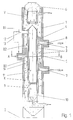
- the ring shaft furnace has a cylindrical casing 1, which is supported on the floor 2 with an approximately vertical axis.
- the inner cylinder 3 is arranged concentrically in it and connected to the jacket 1 via bridges 4.
- the lumpy material 6 is located in the annular space 5 between the jacket 1 and the inner cylinder 3 End of the furnace abandoned and discharged at its lower end after passing through the furnace.
- nozzles 7 are uniformly distributed over the furnace circumference for the supply of hot gases.
- the hot gases can be generated by burners or supplied from other sources.
- the nozzles 7 open in each level under a bridge 4, where a cavity 8 not occupied with lumpy material 6 is formed, from which the gases are distributed into the annular space 5 and flow upwards in the direction of the arrow.
- three nozzles 7 are provided in a cross-sectional plane, the axes of which each enclose an angle of 120 °.
- the nozzles 7 are arranged on the successive cross-sectional planes offset in relation to one another in the circumferential direction such that the nozzles 7 of the following plane are at a gap to the previous one. They are preferably approximately in the middle between two nozzles of the previous level.
- a nozzle 7 is indicated by dash-dotted lines from the feed nozzle plane lying below the cross-sectional plane shown.
- cooling air entering the cooling zone K can enter the closed lower section 10 of the inner cylinder 3 through the discharge end of the furnace which is open at the bottom can flow from there to the outside and be returned to the ring shaft furnace.
- openings 11 to the annular space 5 are also provided in the lower part at approximately the level of the lowermost feed nozzles.
- a line 12 is connected for extracting the hot gases entering the inner cylinder 3 through the openings 11.
- a suction fan can be connected to line 12. This can also be connected via a line 13 indicated by dash-dotted lines to the supply ports 7 of the middle level.
Landscapes
- Engineering & Computer Science (AREA)
- Chemical & Material Sciences (AREA)
- Ceramic Engineering (AREA)
- Physics & Mathematics (AREA)
- Thermal Sciences (AREA)
- Materials Engineering (AREA)
- Structural Engineering (AREA)
- Organic Chemistry (AREA)
- Mechanical Engineering (AREA)
- General Engineering & Computer Science (AREA)
- Vertical, Hearth, Or Arc Furnaces (AREA)
- Furnace Details (AREA)
Abstract
Description
Die Erfindung betrifft einen Ringschachtofen zur Behandlung von stückigem Gut, insbesondere zur thermischen Behandlung von Kalk- und Dolomitgestein zur Umwandlung in Kalk, mit den Merkmalen im Oberbegriff des Anspruchs 1, wie sie aus der DE 3 915 986 C1 bekannt sind. Ein solcher Ringschachtofen besteht aus einem zylindrischen Außenmantel mit im wesentlichen senkrecht stehender Achse, in welchem auf einem Teil seiner Länge ein oder mehrere Innenzylinder unter Bildung eines Ringraums konzentrisch angeordnet sind. Am oberen Ende des Ofens ist eine Schleuse mit Aufgabetrichter zur Beschickung mit stückigem Gut vorgesehen. Die Schleuse soll verhindern, daß bei der diskontinuierlichen Beschickung des Ofens mit stückigem Gut unkontrolliert Gase eintreten bzw. entweichen können. Am unteren Ende des Ringschachtofens ist eine Austragvorrichtung, die das durch Brennen umgewandelte Gut austrägt. Bei jedem Austragvorgang rutscht das im Ringraum des Schachtofens befindliche stückige Gut nach unten und gelangt so nach und nach vom oberen Beschickungsende des Ofens zu seinem unteren Austragende. Auf diesem Weg durch den Ofen erfolgt die chemische Umwandlung mit Hilfe von Heißgasen, die in den Ofen eintreten und den Ofen von unten nach oben durch das stückige Gut hindurch durchströmen. Zur Einleitung dieser Heißgase befinden sich auf mindestens drei voneinander beabstandeten Querschnittsebenen Stutzen am Außenmantel des Ringschachtofens. In jeder Ebene sind die Stutzen auf den Umfang des Ofens zu mehreren verteilt angeordnet. Bei drei Stutzen zum Beispiel stehen die Stutzen unter einem Winkel von 120° zueinander, bei vier Stutzen sind es 90°. In aufeinanderfolgenden Querschnittsebenen stehen die Stutzen so versetzt zueinander, daß mitten zwischen zwei Stutzen der oberen Ebene ein Stutzen der darunter befindlichen Ebene angeordnet ist. Auf diese Weise wird die gleichmäßige Einleitung der Brennergase in die ringförmige Gutsäule sichergestellt. Am oberen Ende des Ringschachtofens bis zur obersten Querschnittsebene, in der Heißgas-Zuführstutzen angeordnet sind, befinden sich, von oben nach unten gesehen, die Vorwärmzone und die erste Brennzone. Zwischen der obersten und der nächstfolgenden unteren Zuführstutzen-Ebene befindet sich die mittlere Brennzone, und zwischen der mittleren bis zur unteren Ebene der Zuführstutzen ist die untere Brennzone gebildet. Von der untersten Ebene der Zuführstutzen bis zum unteren Ende des Schachtofens befindet sich die Kühlzone. Die Heißgase von z.B. mit fossilen gasförmigen oder flüssigen Brennstoffen betriebenen Brennern, ggf. vermischt mit Umwälzgasen, werden durch die einzelnen Stutzen in regelbaren Mengen und je nach Bedarf mit Luft gemischt in einen von stückigem Gut nicht belegten Hohlraum jeweils unter einer Brücke im Ringraum in den Ofen eingeführt und durchströmen das darin befindliche stückige Gut. Um die Zwangsführung der Heißgase von unten nach oben im Ofen zu bewirken und zu fördern, werden die Gase im oberen Teil des Ofens mittels eines Sauggebläses aus dem Ofen abgesaugt oder/und mittels eines Druckgebläses durch den Ofen gedrückt. Bei Anordnung eines Sauggebläses entsteht im Ofen ein Unterdruck gegenüber der umgebenden Atmosphäre. Dies hat den Vorteil, daß man beim Öffnen des Ofens an irgendeiner Stelle nicht mit dem Austritt von unter Druck stehenden Gasen aus dem Ofen rechnen muß. So können erforderlichenfalls Wartungsarbeiten während des Betriebs des Ofens durchgeführt werden.The invention relates to a ring shaft furnace for the treatment of lumpy material, in particular for the thermal treatment of lime and dolomite rock for conversion into lime, with the features in the preamble of
Durch die Austrageöffnungen im unteren Teil des Ringschachtofens kann Kühlluft in die Kühlzone eintreten. Durch eine mittige Absaugung dieser Kühlluft aus der Kühlzone läßt sich die Kühlwirkung durch die Außenluft regulieren.Cooling air can enter the cooling zone through the discharge openings in the lower part of the ring shaft furnace. The cooling effect can be regulated by the outside air by centrally extracting this cooling air from the cooling zone.
Der Ofen kann noch mit verschiedenen Hilfseinrichtungen, wie Wärmetauschern, Umwälzeinrichtungen und dergleichen ausgestattet sein, die aber hier im Zusammenhang mit der Erfindung nicht weiter interessieren.The furnace can also be equipped with various auxiliary devices, such as heat exchangers, circulation devices and the like, but these are of no further interest here in connection with the invention.
Der vorstehend geschilderte bekannte Ringschachtofen ist dazu bestimmt und geeignet, stückiges Gut in verschiedenen Härtestufen zu brennen. So kann insbesondere mehr oder weniger hartgebrannter Kalk aus Kalk- bzw. Dolomitstein durch den abgestuften und geregelten Brennvorgang erzeugt werden.The known ring shaft furnace described above is intended and suitable for burning lumpy material in various degrees of hardness. In particular, more or less hard-burned lime from limestone or dolomite stone can be produced through the graded and regulated firing process.
Der Erfindung liegt nun die Aufgabe zugrunde, einen Ringschachtofen zu schaffen, der sowohl zum Brennen von stückigem Gut in verschiedenen Härtegraden, aber auch zur Erzeugung von weichgebranntem hochreaktivem Gut geeignet ist. Bisher ist ein solcher Ringschachtofen weder in der Konzeption angedacht, noch in der Praxis ausgeführt worden.The invention is based on the object of creating a ring shaft furnace which is suitable both for burning lumpy material in various degrees of hardness and also for producing soft-burned, highly reactive material. So far, such a ring shaft furnace has not been considered in the conception, nor has it been implemented in practice.
Zur Lösung dieser Aufgabe ist erfindungsgemäß ein Ringschachtofen mit den Merkmalen des Anspruch 1 vorgesehen. Die erfindungsgemäße Lösung besteht gegenüber dem Stand der Technik darin, daß der Ringschachtofen in mindestens drei beabstandeten Querschnittszonen in seinem mittleren Teil Heißgas-Zuführstutzen und eine Gasabsaugung durch den Innenzylinder aufweist, wobei die Öffnungen für das Absaugen aus dem Ringraum etwa in Höhe der untersten Heißgas-Zuführstutzenebene gelegen sind. Diese Öffnungen für die Heißgasabsaugungen sind bevorzugt in einer Querschnittsebene am Umfang des Innenzylinders verteilt angeordnet, um die Heißgase gleichmäßig aus dem Ringraum abzusaugen. Um das Absaugen zu bewirken, ist an dem Innenzylinder eine Absaugleitung angeschlossen, die zu einem Unterdruck erzeugenden Aggregat, z. B. einem saugenden Ventilator außerhalb des Ofens führen kann. Alternativ kann in dem Innenzylinder auch ein Unterdruck erzeugendes Aggregat, z. B. ein Absaugventilator, angeordnet sein. Im letzteren Fall ist natürlich die Zugänglichkeit zu dem Ventilator, z.B. wenn eine Reparatur nötig ist, erschwert.To achieve this object, a ring shaft furnace with the features of
Die durch den Innenzylinder abgesaugten Heißgase können entweder einem Wärmetauscher zugeführt werden, oder/und sie werden den mittleren Heißgas-Zuführstutzen zugeführt, so daß sie im Kreislauf umgewälzt werden und damit keine Umweltprobleme verursachen und eine größtmögliche Wärmeausnutzung garantieren.The hot gases drawn off by the inner cylinder can either be fed to a heat exchanger or / and they are fed to the central hot gas feed pipe, so that they are circulated and thus cause no environmental problems and guarantee the greatest possible heat utilization.
In der Zeichnung ist ein Ausführungsbeispiel eines erfindungsgemäßen Ringschachtofens dargestellt, anhand dessen die Erfindung näher erläutert werden soll.
- Fig. 1
- ist ein Längsschnitt und
- Fig. 2
- ein Querschnitt längs der Linie A - B aus Fig. 1.
- Fig. 3
- zeigt in vergrößertem Maßstab im Schnitt C-D aus Fig. 2 eine Brücke zwischen Mantel und Innenzylinder.
- Fig. 1
- is a longitudinal section and
- Fig. 2
- 2 shows a cross section along the line A - B from FIG. 1.
- Fig. 3
- shows an enlarged scale in section CD of Fig. 2, a bridge between the jacket and inner cylinder.
Der Ringschachtofen besitzt einen zylindrischen Mantel 1, der mit etwa vertikaler Achse auf dem Boden 2 abgestützt ist. Konzentrisch in ihm ist der Innenzylinder 3 angeordnet und mit dem Mantel 1 über Brücken 4 verbunden. In dem Ringraum 5 zwischen Mantel 1 und Innenzylinder 3 befindet sich das stückige Gut 6. Dieses wird am oberen Ende des Ofens aufgegeben und an seinem unteren Ende nach dem Durchlaufen des Ofens ausgetragen.The ring shaft furnace has a
Auf mindestens drei beabstandeten Querschnittsebenen sind jeweils drei oder mehrere auf dem Ofenumfang gleichmäßig verteilte Stutzen 7 für die Zufuhr von Heißgasen angeordnet. Die Heißgase können von Brennern erzeugt oder aus anderen Quellen geliefert werden. Die Stutzen 7 münden in jeder Ebene unter jeweils einer Brücke 4, wo sich ein mit stückigem Gut 6 nicht besetzter Hohlraum 8 bildet, aus dem heraus sich die Gase in den Ringraum 5 verteilen und in Pfeilrichtung nach oben strömen. In einer Querschnittsebene sind beispielsweise gemäß Fig. 2 drei Stutzen 7 vorgesehen, deren Achsen jeweils einen Winkel von 120° einschließen. Die Stutzen 7 sind auf den aufeinander folgenden Querschnittsebenen derart in Umfangsrichtung versetzt zueinander angeordnet, daß die Stutzen 7 der folgenden Ebene auf Lücke zur vorhergehenden stehen. Bevorzugt liegen sie etwa in der Mitte zwischen zwei Stutzen der vorhergehenden Ebene. In Fig. 2 ist als Beispiel ein Stutzen 7 aus der unter der dargestellten Querschnittsebene liegenden Zuführstutzenebene strichpunktiert angedeutet.On at least three spaced cross-sectional planes, three or
In dem Ofen bilden sich folgende Zonen aus:
- V
- - Vorwärmzone
- B1
- - obere Brennzone
- B2
- - mittlere Brennzone
- B3
- - untere Brennzone
- K
- - Kühlzone
- V
- - preheating zone
- B1
- - upper firing zone
- B2
- - middle burning zone
- B3
- - lower firing zone
- K
- - cooling zone
Durch Öffnungen 9 kann durch das unten offene Austragende des Ofens in die Kühlzone K eintretende Kühlluft in den geschlossenen unteren Abschnitt 10 des Innenzylinders 3 einströmen, kann von dort nach außen abgeleitet und dem Ringschachtofen wieder zugeführt werden.Through
In dem Innenzylinder 3 sind im unteren Teil ferner etwa in Höhe der untersten Zuführstutzen 7 Öffnungen 11 zum Ringraum 5 vorgesehen. Im oberen Bereich des Innenzylinders 3 ist eine Leitung 12 für eine Absaugung der durch die Öffnungen 11 in den Innenzylinder 3 eintretenden Heißgase angeschlossen. An die Leitung 12 kann ein Sauggebläse angeschlossen sein. Dieses kann weiter über eine strichpunktiert angedeutete Leitung 13 mit den Zuführstutzen 7 der mittleren Ebene verbunden sein.In the inner cylinder 3,
Die Betriebsweise des Ofens gemäß der Erfindung ist nun wie folgt:
- a) Erzeugung von hartgebranntem stückigem Gut
Durch die Zuführstutzen 7 in allen drei Querschnittsebenen wird Heißgas inden Ringraum 5 und das darin befindliche stückigeGut 6 geleitet.Die Leitung 12 ist abgesperrt bzw. das daran angeschlossene nicht dargestellte Unterdruck erzeugende Aggregat ist außer Betrieb.
Durch Variation der eingeblasenen Heißgasmengen und/oder Veränderung der Temperatur der Heißgase kann der gewünschte Härtegrad beim Brennen des stückigen Guts gezielt erreicht werden. Die Temperatur der Heißgase läßt sich z.B. durch Zumischen von Luft oder Umwälzgasen entsprechend variieren. - b) Erzeugung von weichgebranntem hochreaktivem Gut
Die Zuführstutzen 7 in der untersten Querschnittsebene fördern nun kein Heißgas. Dieses wird allein durch dieZuführstutzen 7 in den beiden darüber befindlichen Ebenen indas stückige Gut 6 eingeleitet.Die Leitung 12 zum Unterdruck erzeugenden Aggregat wird geöffnet und dieses wird zur Erzeugung eines Unterdrucks in den Innenzylinder 3 in Betrieb gesetzt. Dadurch bedingt, werden nun durch dieÖffnungen 11 im unteren Abschnitt des Innenzylinders 3aus dem Ringraum 5 des Ofens Heißgase in dem Innenzylinder 3 gesaugt. Es entsteht so indem Ringraum 5 eine Gleichstromzone innerhalb der unteren Brennzone B3, in der von der mittleren Ebene derZuführstutzen 7 zugeführte Heißgase in Förderrichtung des Gutes, also im "Gleichstrom" mit diesem, von der mittleren Ebene derZuführstutzen 7 biszu den Öffnungen 11 strömen, wie in Fig. 1 mit der strichpunktierten Linie 14 angedeutet. Mit dieser Gleichstromzone wird die Voraussetzung für das Erbrennen von hochreaktivem Gut geschaffen.
Der erfindungsgemäße Ofen ermöglicht so die beiden vorgenannten Fahrweisen, um sowohl hartgebranntes als auch weichgebranntes Material zu erzeugen.
- a) Production of hard-burned lumpy goods
Hot gas is passed through thesupply nozzle 7 in all three cross-sectional levels into theannular space 5 and thelumpy material 6 located therein. Theline 12 is shut off or the connected vacuum unit, not shown, is out of operation.
By varying the amount of hot gas blown in and / or changing the temperature of the hot gases, the desired degree of hardness can be achieved in a targeted manner when the lumpy material is fired. The temperature of the hot gases can be varied accordingly, for example by adding air or circulating gases. - b) generation of soft burned highly reactive material
Thesupply nozzle 7 in the lowest cross-sectional plane now do not convey hot gas. This is introduced into the lumpy good 6 solely through thefeed pipe 7 in the two levels above it. Theline 12 to the vacuum generating unit is opened and this is put into operation in order to generate a vacuum in the inner cylinder 3. As a result, hot gases are now drawn into the inner cylinder 3 from theannular space 5 of the furnace through theopenings 11 in the lower section of the inner cylinder 3. This creates a direct current zone in theannular space 5 within the lower combustion zone B3, in which hot gases are supplied from the middle level of thesupply nozzle 7 in the conveying direction of the material, that is to say in “direct current” with it, from the middle level of thesupply nozzle 7 to theopenings 11 flow, as indicated in Fig. 1 with the dash-dottedline 14. This DC zone creates the prerequisite for burning highly reactive material.
The furnace according to the invention thus enables the two aforementioned modes of operation in order to produce both hard-fired and soft-fired material.
Claims (2)
dadurch gekennzeichnet, daß etwa in Höhe der unteren Heißgas-Zuführstutzen (7) im Innenzylinder (3) auf seinem Umfang verteilte seitliche Öffnungen (11) zum Ringraum (5) hin angeordnet sind und am oder im Innenzylinder (3) eine absperrbare Gasabsaugung (12) vorgesehen ist.Ring shaft furnace for the treatment of lumpy material, in particular for the thermal treatment of limestone and dolomite rock, for conversion to lime, with an essentially vertical axis, in which an annular space occupied by material is formed by an inner cylinder, the upper end of which is equipped with a loading device for material and a hot gas suction device, which further has nozzles for the supply of hot gases in at least three spaced cross-sectional planes, which divide the furnace into a preheating zone, into upper, middle and lower combustion zones and cooling zone and the three or more of them uniformly over the circumference of the furnace are distributed and are offset from one level to the other in the circumferential direction by about half a pitch angle and each open under a bridge between the outer jacket of the furnace and the inner cylinder in a cavity not occupied by good, and at the lower discharge for the entry of Cooling air pre see is
characterized in that approximately at the level of the lower hot gas supply ports (7) in the inner cylinder (3) on its circumference are arranged lateral openings (11) towards the annular space (5) and on or in the inner cylinder (3) a lockable gas suction device (12 ) is provided.
dadurch gekennzeichnet, daß die Gasabsaugung (12) zu den mittleren Zuführstutzen (7) führt.Ring shaft furnace according to claim 1,
characterized in that the gas suction (12) leads to the middle feed pipe (7).
Applications Claiming Priority (2)
| Application Number | Priority Date | Filing Date | Title |
|---|---|---|---|
| DE19537435A DE19537435A1 (en) | 1995-10-07 | 1995-10-07 | Ring shaft furnace |
| DE19537435 | 1995-10-07 |
Publications (2)
| Publication Number | Publication Date |
|---|---|
| EP0774635A1 true EP0774635A1 (en) | 1997-05-21 |
| EP0774635B1 EP0774635B1 (en) | 1999-05-26 |
Family
ID=7774306
Family Applications (1)
| Application Number | Title | Priority Date | Filing Date |
|---|---|---|---|
| EP96115275A Expired - Lifetime EP0774635B1 (en) | 1995-10-07 | 1996-09-24 | Ringshaft furnace |
Country Status (3)
| Country | Link |
|---|---|
| EP (1) | EP0774635B1 (en) |
| CN (1) | CN1088825C (en) |
| DE (2) | DE19537435A1 (en) |
Cited By (1)
| Publication number | Priority date | Publication date | Assignee | Title |
|---|---|---|---|---|
| WO2002033338A2 (en) | 2000-10-18 | 2002-04-25 | Krupp Polysius Ag | Method and annular shaft furnace for producing calcined materials |
Families Citing this family (5)
| Publication number | Priority date | Publication date | Assignee | Title |
|---|---|---|---|---|
| CN108168292B (en) * | 2017-11-29 | 2020-02-21 | 方国庆 | A multifunctional and environmentally friendly BSK sintering technology shaft kiln and its use method |
| CN109502999A (en) * | 2018-12-27 | 2019-03-22 | 江苏省建筑材料研究设计院有限公司 | The efficient ash discharging gear of controllable type for active lime energy conservation and environmental protection mechanical shaft kiln |
| BE1028191B9 (en) | 2020-04-07 | 2021-11-30 | Lhoist Rech Et Developpement Sa | Lime or dolomite calcination process and annular upright furnace implemented |
| CN116177984B (en) * | 2021-11-29 | 2024-08-23 | 江西兴华绿色农业开发有限公司 | Safety management method for alkaline earth tea set and wine set platform system |
| BE1032706B1 (en) * | 2024-06-20 | 2026-01-28 | Maerz Ofenbau | Shaft kiln and method for burning carbonate-containing material in a shaft kiln |
Citations (6)
| Publication number | Priority date | Publication date | Assignee | Title |
|---|---|---|---|---|
| DE2710205A1 (en) * | 1977-03-09 | 1978-09-14 | Sueddeutsche Kalkstickstoff | Roasting lime in shaft furnace heated by burning rubbish - with automatic addn. of other fuel depending on heat content of rubbish |
| FR2514341A1 (en) * | 1981-10-13 | 1983-04-15 | Ulrich Beckenbach | PROCESS FOR CALCINING LIME STONE, DOLOMITE OR SIMILAR MATERIALS, AND ANNULAR TANK OVEN FOR ITS IMPLEMENTATION |
| EP0139025A1 (en) * | 1983-10-07 | 1985-05-02 | Kalkwerke H. Oetelshofen GmbH & Co. | Ring shaft furnace |
| US4626200A (en) * | 1985-07-15 | 1986-12-02 | Fuller Company | Shaft kilns having fluid-bed air heater |
| US4668184A (en) * | 1986-07-08 | 1987-05-26 | Fuller Company | Annular shaft kiln |
| DE3915986C1 (en) * | 1989-05-04 | 1990-10-04 | Beckenbach Waermestelle Gmbh, 4000 Duesseldorf, De |
Family Cites Families (6)
| Publication number | Priority date | Publication date | Assignee | Title |
|---|---|---|---|---|
| DE1433832B2 (en) * | 1963-03-16 | 1970-09-10 | Beckenbach, Dipl.-Ing. Karl, 4005 Büderich | Oil or gas heated shaft furnace |
| DE3145549C2 (en) * | 1981-11-17 | 1983-10-13 | Wärmestelle Steine und Erden GmbH, 4000 Düsseldorf | Shaft furnace for firing and sintering lumpy goods with circulating gas extraction |
| EP0082886B2 (en) * | 1981-12-25 | 1989-01-25 | Ulrich Dipl.-Ing. Beckenbach | Process for calcining limestone, dolomite or similar material, and ringshaft furnace for carrying out the process |
| DE3205255C2 (en) * | 1982-02-15 | 1984-10-31 | Rheinisch-Westfälische Kalkwerke AG, 5600 Wuppertal | Method for burning mineral raw materials and device, in particular for carrying out the method |
| DE3718091A1 (en) * | 1987-05-29 | 1988-12-08 | Thyssen Industrie | Device for the heat treatment of predominantly mineral material having a residual calorific value, in particular for ceramicising tailings arising in coal production |
| DE4241939C1 (en) * | 1992-12-11 | 1994-06-16 | Peter Dipl Ing Zeisel | Recycling alkali-contg. circulation gas from combustion zone back to firing zone in shaft furnace - using a mixer tube to add hot gas to the circulation gas which prevents deposits in the injector nozzles. |
-
1995
- 1995-10-07 DE DE19537435A patent/DE19537435A1/en not_active Withdrawn
- 1995-11-15 CN CN95119290A patent/CN1088825C/en not_active Expired - Fee Related
-
1996
- 1996-09-24 DE DE59601989T patent/DE59601989D1/en not_active Expired - Fee Related
- 1996-09-24 EP EP96115275A patent/EP0774635B1/en not_active Expired - Lifetime
Patent Citations (6)
| Publication number | Priority date | Publication date | Assignee | Title |
|---|---|---|---|---|
| DE2710205A1 (en) * | 1977-03-09 | 1978-09-14 | Sueddeutsche Kalkstickstoff | Roasting lime in shaft furnace heated by burning rubbish - with automatic addn. of other fuel depending on heat content of rubbish |
| FR2514341A1 (en) * | 1981-10-13 | 1983-04-15 | Ulrich Beckenbach | PROCESS FOR CALCINING LIME STONE, DOLOMITE OR SIMILAR MATERIALS, AND ANNULAR TANK OVEN FOR ITS IMPLEMENTATION |
| EP0139025A1 (en) * | 1983-10-07 | 1985-05-02 | Kalkwerke H. Oetelshofen GmbH & Co. | Ring shaft furnace |
| US4626200A (en) * | 1985-07-15 | 1986-12-02 | Fuller Company | Shaft kilns having fluid-bed air heater |
| US4668184A (en) * | 1986-07-08 | 1987-05-26 | Fuller Company | Annular shaft kiln |
| DE3915986C1 (en) * | 1989-05-04 | 1990-10-04 | Beckenbach Waermestelle Gmbh, 4000 Duesseldorf, De |
Cited By (2)
| Publication number | Priority date | Publication date | Assignee | Title |
|---|---|---|---|---|
| WO2002033338A2 (en) | 2000-10-18 | 2002-04-25 | Krupp Polysius Ag | Method and annular shaft furnace for producing calcined materials |
| DE10051710A1 (en) * | 2000-10-18 | 2002-05-02 | Krupp Polysius Ag | Process and ring shaft furnace for the production of burned material |
Also Published As
| Publication number | Publication date |
|---|---|
| CN1152109A (en) | 1997-06-18 |
| EP0774635B1 (en) | 1999-05-26 |
| CN1088825C (en) | 2002-08-07 |
| DE19537435A1 (en) | 1997-04-10 |
| DE59601989D1 (en) | 1999-07-01 |
Similar Documents
| Publication | Publication Date | Title |
|---|---|---|
| EP4182622B1 (en) | Parallel-flow regenerative shaft kiln and method for burning carbonate rock | |
| DE102021204176A1 (en) | Co-current counter-current regenerative shaft kiln and method for firing carbonate rock | |
| EP4111118B1 (en) | Device and method for firing and/or calcining lumpy goods | |
| DE102021204175A1 (en) | Lime kiln system for burning carbonate rock and method of converting a PFR shaft kiln to a lime kiln system with a shaft kiln | |
| CH657843A5 (en) | METHOD FOR BURNING AND SINTERING PIECE OF GOODS, ESPECIALLY LIMESTONE OR DOLOMITE, AND RING SHAFT OVEN FOR ITS IMPLEMENTATION. | |
| EP1038851B1 (en) | Process for firing a lumpy, burnable charge expecially limestone, dolomite and magnesite, and a regenerative shaft furnace for carrying out the process | |
| DE102021201549A1 (en) | Device and method for firing and/or calcining lumpy material | |
| DE102020004372A1 (en) | Co-current counter-current regenerative shaft kiln and method for firing carbonate rock | |
| EP3426995B1 (en) | System having a furnace and method for operating such a system | |
| EP0774635B1 (en) | Ringshaft furnace | |
| DE102023102447A1 (en) | Co-current counter-current regenerative shaft kiln and method for firing carbonate rock | |
| DE2534438B2 (en) | Method and device for burning powdery cement raw meal | |
| EP0082886A1 (en) | Process for calcining limestone, dolomite or similar material, and ringshaft furnace for carrying out the process | |
| DE1508494A1 (en) | Device for heating finely divided material such as ores, in particular for use with a pelletizing system | |
| DE102005052753A1 (en) | Plant and process for the production of cement clinker | |
| DE102023130763A1 (en) | Cocurrent-countercurrent regenerative shaft furnace and method for firing carbonate rock | |
| DE2224601A1 (en) | ROTARY STOVES | |
| BE1031596B1 (en) | Direct current-countercurrent regenerative shaft furnace and process for burning carbonate rock | |
| EP4110740A1 (en) | Method for burning carbon-containing material in a pfr shaft furnace | |
| DE4446007A1 (en) | Annular shaft furnace for firing e.g. limestone | |
| BE1029343B1 (en) | Co-current counter-current regenerative shaft kiln and method for firing carbonate rock | |
| EP4577789B1 (en) | Parallel-flow regenerative shaft kiln and method for burning carbonate rock | |
| DE102023112291A1 (en) | Co-current counter-current regenerative shaft kiln and method for firing carbonate rock | |
| DE3833069A1 (en) | Plant for burning lumpy and/or pelleted burning material | |
| LU101654B1 (en) | Process for burning carbonaceous material in a PFR shaft furnace |
Legal Events
| Date | Code | Title | Description |
|---|---|---|---|
| PUAI | Public reference made under article 153(3) epc to a published international application that has entered the european phase |
Free format text: ORIGINAL CODE: 0009012 |
|
| AK | Designated contracting states |
Kind code of ref document: A1 Designated state(s): BE DE FR GB IT |
|
| 17P | Request for examination filed |
Effective date: 19971017 |
|
| GRAG | Despatch of communication of intention to grant |
Free format text: ORIGINAL CODE: EPIDOS AGRA |
|
| GRAG | Despatch of communication of intention to grant |
Free format text: ORIGINAL CODE: EPIDOS AGRA |
|
| GRAH | Despatch of communication of intention to grant a patent |
Free format text: ORIGINAL CODE: EPIDOS IGRA |
|
| 17Q | First examination report despatched |
Effective date: 19981026 |
|
| GRAH | Despatch of communication of intention to grant a patent |
Free format text: ORIGINAL CODE: EPIDOS IGRA |
|
| GRAA | (expected) grant |
Free format text: ORIGINAL CODE: 0009210 |
|
| AK | Designated contracting states |
Kind code of ref document: B1 Designated state(s): BE DE FR GB IT |
|
| PG25 | Lapsed in a contracting state [announced via postgrant information from national office to epo] |
Ref country code: IT Free format text: LAPSE BECAUSE OF FAILURE TO SUBMIT A TRANSLATION OF THE DESCRIPTION OR TO PAY THE FEE WITHIN THE PRESCRIBED TIME-LIMIT;WARNING: LAPSES OF ITALIAN PATENTS WITH EFFECTIVE DATE BEFORE 2007 MAY HAVE OCCURRED AT ANY TIME BEFORE 2007. THE CORRECT EFFECTIVE DATE MAY BE DIFFERENT FROM THE ONE RECORDED. Effective date: 19990526 Ref country code: GB Free format text: LAPSE BECAUSE OF FAILURE TO SUBMIT A TRANSLATION OF THE DESCRIPTION OR TO PAY THE FEE WITHIN THE PRESCRIBED TIME-LIMIT Effective date: 19990526 Ref country code: FR Free format text: LAPSE BECAUSE OF FAILURE TO SUBMIT A TRANSLATION OF THE DESCRIPTION OR TO PAY THE FEE WITHIN THE PRESCRIBED TIME-LIMIT Effective date: 19990526 |
|
| REF | Corresponds to: |
Ref document number: 59601989 Country of ref document: DE Date of ref document: 19990701 |
|
| RAP2 | Party data changed (patent owner data changed or rights of a patent transferred) |
Owner name: BECKENBACH, HELMUTH Owner name: BECKENBACH, ULRICH, DIPL.-ING. |
|
| PG25 | Lapsed in a contracting state [announced via postgrant information from national office to epo] |
Ref country code: BE Free format text: LAPSE BECAUSE OF NON-PAYMENT OF DUE FEES Effective date: 19990930 |
|
| EN | Fr: translation not filed |
Owner name: BECKENBACH, HELMUTH |
|
| GBV | Gb: ep patent (uk) treated as always having been void in accordance with gb section 77(7)/1977 [no translation filed] |
Effective date: 19990526 |
|
| BERE | Be: lapsed |
Owner name: BECKENBACH WARMESTELLE G.M.B.H. Effective date: 19990930 |
|
| PLBE | No opposition filed within time limit |
Free format text: ORIGINAL CODE: 0009261 |
|
| STAA | Information on the status of an ep patent application or granted ep patent |
Free format text: STATUS: NO OPPOSITION FILED WITHIN TIME LIMIT |
|
| 26N | No opposition filed | ||
| PGFP | Annual fee paid to national office [announced via postgrant information from national office to epo] |
Ref country code: DE Payment date: 20041022 Year of fee payment: 9 |
|
| PG25 | Lapsed in a contracting state [announced via postgrant information from national office to epo] |
Ref country code: DE Free format text: LAPSE BECAUSE OF NON-PAYMENT OF DUE FEES Effective date: 20060401 |