EP0773089B1 - Outil pour le rabotage manuel d'une bande - Google Patents
Outil pour le rabotage manuel d'une bande Download PDFInfo
- Publication number
- EP0773089B1 EP0773089B1 EP96117141A EP96117141A EP0773089B1 EP 0773089 B1 EP0773089 B1 EP 0773089B1 EP 96117141 A EP96117141 A EP 96117141A EP 96117141 A EP96117141 A EP 96117141A EP 0773089 B1 EP0773089 B1 EP 0773089B1
- Authority
- EP
- European Patent Office
- Prior art keywords
- belt
- blade
- planing device
- base member
- hold down
- Prior art date
- Legal status (The legal status is an assumption and is not a legal conclusion. Google has not performed a legal analysis and makes no representation as to the accuracy of the status listed.)
- Expired - Lifetime
Links
Images


Classifications
-
- B—PERFORMING OPERATIONS; TRANSPORTING
- B26—HAND CUTTING TOOLS; CUTTING; SEVERING
- B26D—CUTTING; DETAILS COMMON TO MACHINES FOR PERFORATING, PUNCHING, CUTTING-OUT, STAMPING-OUT OR SEVERING
- B26D3/00—Cutting work characterised by the nature of the cut made; Apparatus therefor
- B26D3/06—Grooving involving removal of material from the surface of the work
- B26D3/065—On sheet material
-
- B—PERFORMING OPERATIONS; TRANSPORTING
- B26—HAND CUTTING TOOLS; CUTTING; SEVERING
- B26D—CUTTING; DETAILS COMMON TO MACHINES FOR PERFORATING, PUNCHING, CUTTING-OUT, STAMPING-OUT OR SEVERING
- B26D3/00—Cutting work characterised by the nature of the cut made; Apparatus therefor
- B26D3/02—Bevelling
-
- B—PERFORMING OPERATIONS; TRANSPORTING
- B27—WORKING OR PRESERVING WOOD OR SIMILAR MATERIAL; NAILING OR STAPLING MACHINES IN GENERAL
- B27G—ACCESSORY MACHINES OR APPARATUS FOR WORKING WOOD OR SIMILAR MATERIALS; TOOLS FOR WORKING WOOD OR SIMILAR MATERIALS; SAFETY DEVICES FOR WOOD WORKING MACHINES OR TOOLS
- B27G17/00—Manually-operated tools
- B27G17/02—Hand planes
- B27G17/025—Hand planes for forming profiles on wood; for trimming or chamfering edges
Definitions
- the invention relates to a manually movable belt slicer for Removing the top layer or part of the top layer from one end of a conveyor belt, with a base body, the one has flat support surface and to which a handle is attached is, as well as with a knife stored in the base body.
- Such manually movable belt slicers are generally known and serve to cover the top layer or parts of the top layer Remove the end of a conveyor belt. It is common here that Secure the end of the belt against slipping on a support device and then carry out the processing with the planer, the Plane is pulled by hand.
- the structure is similar the belt slicer a carpenter slicer, which is guided by hand.
- the belt slicer lies on it with its flat contact surface the conveyor belt, the sloping, below on the Cutting surface protruding knife cuts off top layer strips, so that wavy depressions in the conveyor belt arise.
- DE 40 02 116 C2 describes a mechanical belt slicer for Planing a top layer from one end to one Support device clamped conveyor belt known.
- the Belt plane has a movable along the support device Sled on, in which a knife and a leading one Pressure shoe according to the thickness of the cover layer to be cut or the thickness of the conveyor belt adjustable in height are stored.
- the knife is designed as a thick, rigid blade, whose free end turned away from the sled to cut off the top layer vertically and horizontally.
- the carriage is moved by means of a gear transmission, that can be operated using a hand crank.
- the Thick and therefore rigid blade ensures that over the a constant cover layer thickness is removed across the entire belt width becomes.
- the disadvantage of this mechanical belt slicer is, however, that it requires a lot of construction work with the associated high production costs. Apart from this, the Users on site, especially if the the belt connectors or fastening clips connecting the belt ends new belt connectors or fastening clips on the belt need to be attached, an uncomplicated removal of the Top layer or part of the top layer of that for which Attach the belt connectors or fastening clips prepared Belt end hardly possible.
- the performance properties a belt slicer of the type mentioned above improve that with this, despite being exclusively manual Handling, with little effort the cover layer or parts the top layer of one end of a conveyor belt over a large area can be removed.
- the base body with its bearing surface does not rest on the conveyor belt as in the above discussed manually movable belt slicer, which is in the manner of a Carpenter plane is formed, but it is the basic body with its contact surface on the flat surface which also supports the conveyor belt. It is also essential that the arranged perpendicular to the contact surface of the base body, in Direction of movement of the belt plane Use of the belt slicer on the front, thus free end face of the conveyor belt, with which a defined guidance of the base body and thus also of the hold-down device and the blade is guaranteed. Training is particularly important of the knife as a thin blade.
- This design is a prerequisite for the cover layer or part of the cover layer of the conveyor belt with a small, thus manually attachable Force can be cut off.
- the design of the blade is the problem that it is flexible, and thus the special interaction of the blade and hold-down is required to achieve a satisfactory To achieve a cutting result.
- a thin, pliable blade is for example one that is used in so-called carpet knives Is used.
- This is also of major importance Hold-down device that not only has the function of the blade leading area of the conveyor belt against the pad the conveyor belt is resting, but also the vertical one Guiding the body and thus the blade.
- the belt slicer according to the invention can be used in practice achieve excellent cutting results. This seems so justifiable that in the event that when removing the top layer or a part of the cover layer from the end of the conveyor belt due to their flexible property in the area of their free Wants to cut deeper into the conveyor belt than desired, an effective support force of the blade against the bending force of the blade Hold down on the conveyor belt, which ensures that the blade is straight, with little force, by the Belt is moved through.
- the curved area of the blade limits the width of the the belt strip to be cut out.
- the extension of the is the bent area of the blade in the direction of the belt height to be dimensioned so that even when the blade is at Cutting bends, the free end of the curved blade section protrudes from the belt at the top.
- the hold-down is useful as a strip-shaped, rectangular Cross-sectional component formed. This Design combines optimal functionality with special simple design.
- a special embodiment of the invention provides that the Hold-down device and the blade can be adjusted to each other in the basic body are stored. Because of the thin, flexible training of the Blade and thus the difficulty of adjusting it in a defined way should it be in a fixed position in the Main body be kept. It only needs the hold-down device be adjustable.
- the hold-down is expediently height-adjustable and / or around an axis running in the direction of movement of the belt plane pivoted in the body.
- the depth of the cut that is performed by the blade it can only by changing the vertical position of the hold-down device achieve what the pivot position of the hold-down in particular the function comes, the defined, straightforward Ensure movement of the blade through the conveyor belt.
- the hold-down device has a flat hold-down surface has that parallel or at an acute angle to not bent section of the blade, based on the cantilever Ends of hold-down device and blade, is arranged.
- the acute angle between the hold-down surface and the one not bent up Section of the blade should be less than 5 °. Because of the arrangement of hold-down and not bent up Section of the blade, the hold-down lies, depending on the cutting condition, either only in the area of its free end or along its hold-down surface projecting over the base body on the top layer of the conveyor belt.
- the hold-down device is used the base body due to the forces arising from the Line contact in the area of the free end of the hold-down in the surface contact moves over the hold-down surface with which Consequence that the position of the blade relative to the belt adjusted in such a way that the free end of the blade Has endeavored to move upwards more in the conveyor belt.
- the result is that the surface contact of the hold-down surface can be canceled again. As a consequence, this means that during the cutting process the body with his level support surface is not necessarily on the conveyed goods receiving document.
- This acute angle is suitably less than 15 °, it lies in particular between 10 and 15 °.
- the cutting edge of the non-bent section of the blade is advantageous perpendicular to the direction of movement of the belt plane arranged.
- the bending behavior of the thin Blade can be positively influenced, that is in the sense of a Reduction of unwanted bend. For example, this is possible if the tip of the bent end of the blade is on the trailing surface in the direction of movement of the belt slicer Hold-down device.
- the top layer of the conveyor belt, in the end area of the conveyor belt planing in whole or in part can vary be designed. As a rule, it will be a circulation pattern act that has to be cut off to be an immediate, large-scale installation of the belt connector or fastening clips on the conveyor belt and thus to ensure their optimal connection.
- the overlay pattern can be diamond-shaped, for example exhibit.
- the manually operated belt slicer according to the invention is in the Contrary to the belt slicer discussed in the prior art in kind of a planer that is pulled over the conveyor belt primarily intended for pressurization. Due to the from the user of the plane over his arm diagonally from above into the Handle and thus the basic body initiated actuation force, the main body and thus the hold-down device becomes firm pressed against the conveyor belt, with the consequence, one optimal hold-down and guiding function of the hold-down device.
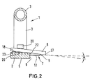
- the Belt plane 1 a cuboid, designed in the manner of a bar Base body 2 and a U-shaped tube Handle 3 on. This is in the area of its free ends the base body 2 in the region of its opposite ends welded, the central longitudinal axis of the handle 3 with the central longitudinal axis 4 of the base body coincides.
- the one Handle 3 facing away from the base body 2 represents its Contact surface 5 and the visible side surface of the Base body 2 represents its contact surface 6.
- base body 2 is a thin, flexible blade 7 and, this in the intended Direction of movement D of the belt slicer 1 in advance Hold-down 8 attached. These parts are attached in the middle area of the base body 2, i.e. about halfway there Length.
- the blade has a trapezoidal shape, with a pointed corner region 9 the blade 7, based on the representation of the blade 7 in Figure 1 is bent up, that is from the bearing surface 5 of the Base body 2 is bent away.
- For receiving the blade 7 points the base body 2 in the area of its upper surface 10 Milled 11 on the surface 10, and also to the support surface 5 of the base body 2 an angle ⁇ between 10 and 15 ° includes.
- the cutting edge 12 of the blade 7 lies in the area the right-angled corner 13 of the cutout 11 on it and it is the blade 7 by means of a screw 14 with the base body 2 firmly connected in a threaded hole 15 of the base body 2 is screwed in.
- the cutting edge 12 perpendicular to the direction of movement D of the belt plane 1 arranged.
- the screw 14 is located itself close to the contact surface 6 and the blade 7 is around such a measure of the base body 2 in the area of the contact surface 6, which is about half the total length of the cutting edge 12 corresponds.
- Points in the direction of movement D of the base body 2 this, in front of the oblique cutout 11, one parallel to the upper one Milled surface 17 of the base body 2 positioned on, whose width is that of the rectangular flat hold-down 8 corresponds. This lies with its in the direction of movement D leading, positioned perpendicular to the direction of movement D.
- the hold-down 8 extends over the entire Width of the base body 2 and also protrudes by a measure in Direction of the bent end of the blade 7 over the base body 2, which is slightly less than half the length of the Hold-down 8.
- the lateral edge 22 of the base body 2 in the area of Milling 17 for the hold-down 8 is in a larger size Distance to the support surface 5 of the base body 2 arranged as the corner 13 of the cutout 11 for the blade 7.
- Symmetrical to Screw 20 and the central longitudinal axis 4 of the base body 2 has the hold-down 8 has two threaded bores 23 and 24 into which screws, not shown, are screwed in, which are support on the base body 2, which gives the opportunity to screwing these screws through the Hold-down 8, with corresponding loosening of the screw 20, the hold-down 8 at any vertical distance from the support surface 5 of the base body 2 and any tilt position to position this.
- Figures 1 to 3 show the hold-down device 8 in a tilted around the edge 22 of the base body 2 Position in which the lower edge 18 of the hold-down 8th an acute angle ⁇ to the cutting edge 12 of the blade 7 in the does not occupy a bent area. This angle is maximum 5 °.
- Figure 1 further illustrates that in this Position the corner 9 with its tip the side surface 25 of the Hold-down contacted.
- the belt slicer 1 For removing the top layer or part of the top layer from one end of a conveyor belt, the belt slicer 1 is attached its base body 2 in the area of its contact surface 6 on the End face of the belt end positioned, this end face the belt end initially only with the contact surface 6 in the range of the cutting edge 12 of the blade 7 up to the leading end 26 of the base body 2 comes into contact.
- the hold-down 8 is thus at least in the area of its free edge 27 on the belt on.
- the user holds the end of the belt with his left hand and presses the belt slicer 1 in the direction of movement with his right hand D, with which the inclined blade 7 through the belt is moved through and in the area of the end of the top layer or removed part of the top layer.
- the hold-down 8 is adjusted so that the removal of the top layer or a Part of the top layer of the belt when driving over the Gurtendes by means of the belt slicer 1, due to the Interaction of blade 7 and hold-down 8 ensured is that even with the thin, pliable formation of the blade 7 this is moved through the belt defined. That way reduced in strength can be belt connectors or Fastening clips are attached in the area of the belt end. This is disclosed, for example, in EP 628 747 A1.
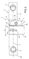
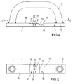
- FIGs 6 to 8 illustrate the second embodiment of the manually movable belt slicer according to the invention.
- FIGs 1 to 5 matching parts are labeled with the same reference numerals for the sake of simplicity.
- the belt slicer according to FIGS. 6 to 8 differs from the embodiment of Figures 1 to 5 by the changed Design of the blade 7 and its storage in the base body 2 of the girdle, further through the changed training and Storage of the hold-down 8.
- the hold-down 8 is fastened by means of the screw 20, wherein the screw in this second embodiment with a Pin section 29 rotatable in a bore of the without radial play Main body 2 is held.
- the screw is axially 20 in Main body 2 held by means of a disc 30 which by a Screw 31 connected to the pin portion 29 of the screw 20 is and is supported on the base body 2.
- the base body 2 has this in the area of its support surface 5 is cylindrical Recess 32 on both the head of the screw 31 and the disc 30 picks up so that it does not have the bottom Protect the bearing surface 5 of the base body 2.
- the hold-down 8 is provided with a threaded bore 33, which in the threaded portion 34 engages the screw 20, whereby a rotary movement the screw 20 to a parallel adjustment movement of the Hold-down 8 in a direction perpendicular to the upper surface 10 of the base body 2 leads.
- interspersed compression spring 37 arranged to ensure is that the screw 20 in use of the belt plane not adjusted.
Landscapes
- Life Sciences & Earth Sciences (AREA)
- Forests & Forestry (AREA)
- Engineering & Computer Science (AREA)
- Mechanical Engineering (AREA)
- Wood Science & Technology (AREA)
- Manufacture Of Wood Veneers (AREA)
- Details Of Cutting Devices (AREA)
Claims (17)
- Rabot de bande déplaçable à la main pour retirer la couche superficielle ou une partie de celle-ci à l'extrémité d'une bande transporteuse, comportant un corps de base présentant une face d'appui plane et auquel est fixée une poignée, ainsi qu'un couteau monté sur le corps de base,
caractérisé en ce quele corps de base (2) présente, perpendiculaire à sa face d'appui (5) une portée (6) orientée selon la direction de déplacement (D) du rabot (1),le couteau (7) est une lame mince qui, du côté de la portée (6) du corps de base (2) dépasse celle-ci, par une extrémité (9) recourbée vers le haut,dans le corps de base (2) et en avant de la lame (7) selon la direction de déplacement (D) se trouve un serreflan (8) qui, du côté de la portée (6) du corps de base (2) dépasse cette portée et est monté au-dessus du bord de coupe (12) de la partie non recourbée (16) de la lame (7). - Rabot à bande selon la revendication 1,
caractérisé en ce que
le serre-flan (8) et la lame (7) sont montés dans le corps de base (2) avec possibilité de déplacement de l'un par rapport à l'autre. - Rabot à bande selon la revendication 2,
caractérisé en ce que
le serre-flan (8) est monté sur le corps de base (2) avec possibilité de réglage en hauteur. - Rabot à bande selon la revendication 3,
caractérisé en ce que
le serre-flan (8) est monté sur le corps de base (2) de manière à pouvoir se déplacer parallèlement ou à pouvoir basculer autour d'un axe parallèle à la direction de déplacement (D) du rabot. - Rabot à bande selon une des revendications 1 à 4,
caractérisé en ce que
le serre-flan (8) est un composant ayant la forme d'une baguette à section rectangulaire. - Rabot à bande selon une des revendications 1 à 5,
caractérisé en ce que
le serre-flan (8) présente une portée d'arrêt plane. - Rabot à bande selon la revendication 6,
caractérisé en ce que
la portée d'arrêt du serre-flan est montée en faisant un angle aigu α avec la partie non recourbée (16) de la lame (7) du côté des extrémités dépassantes de serre-flan et de la lame (7). - Rabot à bande selon la revendication 7,
caractérisé en ce que
l'angle aigu α est inférieur à 5°. - Rabot à bande selon une des revendications 1 à 8,
caractérisé en ce que
la partie non recourbée (16) de la lame (7) fait un angle β avec la face d'appui plane (5) du corps de base (1). - Rabot à bande selon la revendication 9,
caractérisé en ce que
l'angle aigu β est inférieur à 15°, et compris en particulier entre 10° et 15°. - Rabot à bande selon une des revendications 1 à 10,
caractérisé en ce que
le bord de coupe (12) de la partie non recourbée (16) de la lame (7) est perpendiculaire à la direction de déplacement (D) du rabot (1). - Rabot à bande selon une des revendications 1 à 11,
caractérisé en ce que
la partie (9) recourbée vers le haut, de la lame (7) est pratiquement perpendiculaire à la partie (16) non recourbée de la lame (7). - Rabot à bande selon une des revendications 1 à 12,
caractérisé en ce que
la lame (7) comporte des extrémités (9), identiques et recourbées en sens contraires. - Rabot à bande selon la revendication 13,
caractérisé en ce que
la lame est en prise par son extrémité (9) recourbée vers le bas, dans un évidement (28) du corps de base. - Rabot à bande selon une des revendications 1 à 14,
caractérisé en ce que
la pointe de l'extrémité (9) recourbée vers le haut, de la lame (7) est en appui sur la portée (25) du serre-flan (8) située vers l'arrière par rapport au sens de déplacement (D) du rabot. - Rabot à bande selon une des revendications 1 à 15,
caractérisé en ce que
le serre-flan (8) est monté réglable sur le corps de base (2) par l'intermédiaire d'au moins une vis (20). - Rabot à bande selon la revendication 15,
caractérisé en ce que
la vis (20) fixée axialement dans le corps de base (2) peut tourner et sa partie filetée (34) est engagée dans l'alésage fileté du serre-flan (8) qui lui-même est positionné dans le corps de base (2) avec solidarité en rotation, par l'intermédiaire d'un organe de maintien (35) monté dans le corps de base (2).
Applications Claiming Priority (2)
| Application Number | Priority Date | Filing Date | Title |
|---|---|---|---|
| DE19541822A DE19541822A1 (de) | 1995-11-09 | 1995-11-09 | Manuell bewegbarer Gurthobel |
| DE19541822 | 1995-11-09 |
Publications (2)
| Publication Number | Publication Date |
|---|---|
| EP0773089A1 EP0773089A1 (fr) | 1997-05-14 |
| EP0773089B1 true EP0773089B1 (fr) | 2000-01-12 |
Family
ID=7777048
Family Applications (1)
| Application Number | Title | Priority Date | Filing Date |
|---|---|---|---|
| EP96117141A Expired - Lifetime EP0773089B1 (fr) | 1995-11-09 | 1996-10-25 | Outil pour le rabotage manuel d'une bande |
Country Status (3)
| Country | Link |
|---|---|
| US (1) | US5771587A (fr) |
| EP (1) | EP0773089B1 (fr) |
| DE (2) | DE19541822A1 (fr) |
Families Citing this family (6)
| Publication number | Priority date | Publication date | Assignee | Title |
|---|---|---|---|---|
| EP1245352B1 (fr) * | 2001-03-23 | 2005-02-02 | MATO Maschinen- und Metallwarenfabrik Curt Matthaei GmbH & Co KG | Rabot refendeur à main destiné aux courroies |
| US20050229403A1 (en) * | 2003-09-08 | 2005-10-20 | Diaz Bob M | Method and apparatus for cutting materials |
| DE502006001891D1 (de) * | 2006-04-29 | 2008-12-04 | Mato Masch & Metallwaren | Einrichtung zum Abtrennen von Deckschichten von einem Ende eines Fördergurts |
| CN106541434B (zh) * | 2016-11-30 | 2018-06-22 | 上海荣南科技有限公司 | 一种天窗密封条精切机机械装置 |
| US11167439B2 (en) | 2020-03-20 | 2021-11-09 | Mayer Engineering, LLC | Precision skiver |
| US20210291395A1 (en) * | 2020-03-20 | 2021-09-23 | Mayer Engineering, LLC | Precision Skiver |
Family Cites Families (13)
| Publication number | Priority date | Publication date | Assignee | Title |
|---|---|---|---|---|
| US2734535A (en) * | 1956-02-14 | neubauer | ||
| GB814840A (en) * | 1956-10-23 | 1959-06-10 | C & J Hampton Ltd | Improvements in or relating to slitting tools |
| US421407A (en) * | 1890-02-18 | Molding-plane | ||
| US1307151A (en) * | 1919-06-17 | Paper-cutter | ||
| US991238A (en) * | 1910-09-22 | 1911-05-02 | William Potter | Rabbet-plane. |
| US1393991A (en) * | 1920-09-24 | 1921-10-18 | John M Dodenhof | Plane |
| US1576661A (en) * | 1925-03-17 | 1926-03-16 | Lawrence August | Plane |
| US4656910A (en) * | 1986-03-03 | 1987-04-14 | The Goodyear Tire & Rubber Company | Belt skiving method and apparatus |
| AU585464B2 (en) * | 1986-08-19 | 1989-06-15 | Anatoly George Szogi | Panel cutting apparatus |
| AU616338B2 (en) * | 1989-02-02 | 1991-10-24 | Mato Maschinen- Und Metallwarenfabrik Curt Matthaei Gmbh & Co Kg | Belt skimming device |
| US4983081A (en) * | 1989-06-01 | 1991-01-08 | Glass Master Corporation | Apparatus and method for forming shiplap duct |
| US5040297A (en) * | 1989-12-01 | 1991-08-20 | Malco Products, Inc. | Fiberglass panel cutter with adjustable square and duct knife |
| DE4318836A1 (de) * | 1993-06-07 | 1994-12-08 | Mato Masch & Metallwaren | Verbindungselement für Förderbänder |
-
1995
- 1995-11-09 DE DE19541822A patent/DE19541822A1/de not_active Withdrawn
-
1996
- 1996-10-25 DE DE59604166T patent/DE59604166D1/de not_active Expired - Lifetime
- 1996-10-25 EP EP96117141A patent/EP0773089B1/fr not_active Expired - Lifetime
- 1996-11-06 US US08/744,795 patent/US5771587A/en not_active Expired - Lifetime
Also Published As
| Publication number | Publication date |
|---|---|
| EP0773089A1 (fr) | 1997-05-14 |
| DE59604166D1 (de) | 2000-02-17 |
| DE19541822A1 (de) | 1997-05-15 |
| US5771587A (en) | 1998-06-30 |
Similar Documents
| Publication | Publication Date | Title |
|---|---|---|
| EP0525438B1 (fr) | Scie circulaire portative à moteur pour travail manuel | |
| DE3509515C2 (fr) | ||
| EP0773089B1 (fr) | Outil pour le rabotage manuel d'une bande | |
| DE3615848C3 (de) | Für Trennarbeiten verwendbare Handwerkzeugmaschine wie Handkreissäge, Trennschleifgerät od. dgl. | |
| EP0305414B1 (fr) | Couteau | |
| DE3729159C1 (de) | Geraet zum Schneiden von Obst,Gemuese oder dergleichen in Scheiben | |
| EP1306149A2 (fr) | Dispositif de décroutage à tête de décroutage pivotante | |
| EP0215073B1 (fr) | Scie sauteuse | |
| EP3150343A1 (fr) | Mandoline | |
| CH684687A5 (de) | Schneidwerkzeug. | |
| DE68902296T2 (de) | Anordnung fuer schneideinsatzhalter. | |
| DE3615381C2 (de) | Fuehrungsvorrichtung fuer den messerbalken einer schere zur blechbearbeitung | |
| DE2642656C3 (de) | Tafelschere | |
| EP0090171A2 (fr) | Dispositif pour le mortaisage du bois, du bois composé et de matériaux similaires | |
| DE3422570A1 (de) | Messerhalter fuer ein scherenschnittmesser an rollenschneidmaschinen | |
| EP0204023B1 (fr) | Guidage longitudinal, spécialement pour une scie circulaire | |
| DE3540410A1 (de) | Fuer trennarbeiten verwendbare handwerkzeugmaschine wie handkreissaege, trennschleifgeraet od.dgl. | |
| WO2003072321A1 (fr) | Trancheuse universelle a plaque de reglage | |
| EP3782754B1 (fr) | Lime destinée à limer la denture de coupe d'une chaîne coupante | |
| DE10300972A1 (de) | Schleifvorrichtung für rotierend angetriebene Kreismesser | |
| EP0118077A2 (fr) | Butée à onglets | |
| EP1245352A1 (fr) | Rabot refendeur à main destiné aux courroies | |
| DE29601840U1 (de) | Schleifvorrichtung | |
| CH662771A5 (de) | Schneidvorrichtung fuer bogen und hefte. | |
| DE2144221A1 (de) | Aus Schneidklinge und Fuhrung be stehendes Werkzeug zum Schneiden von Flachmatenal |
Legal Events
| Date | Code | Title | Description |
|---|---|---|---|
| PUAI | Public reference made under article 153(3) epc to a published international application that has entered the european phase |
Free format text: ORIGINAL CODE: 0009012 |
|
| AK | Designated contracting states |
Kind code of ref document: A1 Designated state(s): DE FR GB |
|
| 17P | Request for examination filed |
Effective date: 19970714 |
|
| GRAG | Despatch of communication of intention to grant |
Free format text: ORIGINAL CODE: EPIDOS AGRA |
|
| 17Q | First examination report despatched |
Effective date: 19990319 |
|
| GRAG | Despatch of communication of intention to grant |
Free format text: ORIGINAL CODE: EPIDOS AGRA |
|
| GRAH | Despatch of communication of intention to grant a patent |
Free format text: ORIGINAL CODE: EPIDOS IGRA |
|
| GRAH | Despatch of communication of intention to grant a patent |
Free format text: ORIGINAL CODE: EPIDOS IGRA |
|
| GRAA | (expected) grant |
Free format text: ORIGINAL CODE: 0009210 |
|
| AK | Designated contracting states |
Kind code of ref document: B1 Designated state(s): DE FR GB |
|
| REF | Corresponds to: |
Ref document number: 59604166 Country of ref document: DE Date of ref document: 20000217 |
|
| GBT | Gb: translation of ep patent filed (gb section 77(6)(a)/1977) |
Effective date: 20000321 |
|
| ET | Fr: translation filed | ||
| PLBE | No opposition filed within time limit |
Free format text: ORIGINAL CODE: 0009261 |
|
| STAA | Information on the status of an ep patent application or granted ep patent |
Free format text: STATUS: NO OPPOSITION FILED WITHIN TIME LIMIT |
|
| 26N | No opposition filed | ||
| REG | Reference to a national code |
Ref country code: GB Ref legal event code: IF02 |
|
| REG | Reference to a national code |
Ref country code: DE Ref legal event code: R082 Ref document number: 59604166 Country of ref document: DE Representative=s name: PATENTANWAELTE QUERMANN, STURM, WEILNAU, DE |
|
| REG | Reference to a national code |
Ref country code: DE Ref legal event code: R082 Ref document number: 59604166 Country of ref document: DE Representative=s name: QUERMANN STURM WEILNAU PATENTANWAELTE PARTNERS, DE Effective date: 20140217 Ref country code: DE Ref legal event code: R082 Ref document number: 59604166 Country of ref document: DE Representative=s name: PATENTANWAELTE QUERMANN, STURM, WEILNAU, DE Effective date: 20140217 Ref country code: DE Ref legal event code: R081 Ref document number: 59604166 Country of ref document: DE Owner name: MATO GMBH & CO. KG, DE Free format text: FORMER OWNER: MATO MASCHINEN- UND METALLWARENFABRIK CURT MATTHAEI GMBH & CO KG, 63071 OFFENBACH, DE Effective date: 20140217 |
|
| PGFP | Annual fee paid to national office [announced via postgrant information from national office to epo] |
Ref country code: FR Payment date: 20141022 Year of fee payment: 19 Ref country code: GB Payment date: 20141021 Year of fee payment: 19 |
|
| PGFP | Annual fee paid to national office [announced via postgrant information from national office to epo] |
Ref country code: DE Payment date: 20141223 Year of fee payment: 19 |
|
| REG | Reference to a national code |
Ref country code: DE Ref legal event code: R119 Ref document number: 59604166 Country of ref document: DE |
|
| GBPC | Gb: european patent ceased through non-payment of renewal fee |
Effective date: 20151025 |
|
| PG25 | Lapsed in a contracting state [announced via postgrant information from national office to epo] |
Ref country code: DE Free format text: LAPSE BECAUSE OF NON-PAYMENT OF DUE FEES Effective date: 20160503 Ref country code: GB Free format text: LAPSE BECAUSE OF NON-PAYMENT OF DUE FEES Effective date: 20151025 |
|
| REG | Reference to a national code |
Ref country code: FR Ref legal event code: ST Effective date: 20160630 |
|
| PG25 | Lapsed in a contracting state [announced via postgrant information from national office to epo] |
Ref country code: FR Free format text: LAPSE BECAUSE OF NON-PAYMENT OF DUE FEES Effective date: 20151102 |