EP0772099A2 - Dual voltage driven transfer assist apparatus - Google Patents
Dual voltage driven transfer assist apparatus Download PDFInfo
- Publication number
- EP0772099A2 EP0772099A2 EP19960307859 EP96307859A EP0772099A2 EP 0772099 A2 EP0772099 A2 EP 0772099A2 EP 19960307859 EP19960307859 EP 19960307859 EP 96307859 A EP96307859 A EP 96307859A EP 0772099 A2 EP0772099 A2 EP 0772099A2
- Authority
- EP
- European Patent Office
- Prior art keywords
- copy sheet
- solenoid
- operative position
- blade
- contact
- Prior art date
- Legal status (The legal status is an assumption and is not a legal conclusion. Google has not performed a legal analysis and makes no representation as to the accuracy of the status listed.)
- Withdrawn
Links
- 230000009977 dual effect Effects 0.000 title claims abstract description 22
- 238000012546 transfer Methods 0.000 title abstract description 77
- 238000003825 pressing Methods 0.000 claims abstract description 15
- 230000004044 response Effects 0.000 claims description 22
- 238000003384 imaging method Methods 0.000 claims description 14
- 238000007639 printing Methods 0.000 claims description 12
- 230000000694 effects Effects 0.000 claims description 7
- 230000001186 cumulative effect Effects 0.000 claims 1
- 230000007246 mechanism Effects 0.000 abstract description 4
- 239000000843 powder Substances 0.000 description 25
- 239000002245 particle Substances 0.000 description 19
- 239000000758 substrate Substances 0.000 description 16
- 239000000463 material Substances 0.000 description 15
- 238000000034 method Methods 0.000 description 12
- 230000008569 process Effects 0.000 description 10
- 238000012217 deletion Methods 0.000 description 8
- 230000037430 deletion Effects 0.000 description 8
- 108091008695 photoreceptors Proteins 0.000 description 8
- 238000011161 development Methods 0.000 description 6
- 239000008187 granular material Substances 0.000 description 5
- 238000012545 processing Methods 0.000 description 5
- 238000004140 cleaning Methods 0.000 description 4
- 230000002457 bidirectional effect Effects 0.000 description 3
- 229920002799 BoPET Polymers 0.000 description 2
- 239000000853 adhesive Substances 0.000 description 2
- 230000001070 adhesive effect Effects 0.000 description 2
- 238000013459 approach Methods 0.000 description 2
- 239000003795 chemical substances by application Substances 0.000 description 2
- 230000001934 delay Effects 0.000 description 2
- 230000005686 electrostatic field Effects 0.000 description 2
- 230000007704 transition Effects 0.000 description 2
- 239000002699 waste material Substances 0.000 description 2
- 239000005041 Mylar™ Substances 0.000 description 1
- BUGBHKTXTAQXES-UHFFFAOYSA-N Selenium Chemical compound [Se] BUGBHKTXTAQXES-UHFFFAOYSA-N 0.000 description 1
- RTAQQCXQSZGOHL-UHFFFAOYSA-N Titanium Chemical compound [Ti] RTAQQCXQSZGOHL-UHFFFAOYSA-N 0.000 description 1
- 230000009471 action Effects 0.000 description 1
- 238000013019 agitation Methods 0.000 description 1
- 238000005452 bending Methods 0.000 description 1
- 230000000903 blocking effect Effects 0.000 description 1
- 230000001276 controlling effect Effects 0.000 description 1
- 230000007812 deficiency Effects 0.000 description 1
- 238000010586 diagram Methods 0.000 description 1
- 230000008030 elimination Effects 0.000 description 1
- 238000003379 elimination reaction Methods 0.000 description 1
- 238000005516 engineering process Methods 0.000 description 1
- 230000002708 enhancing effect Effects 0.000 description 1
- 230000006353 environmental stress Effects 0.000 description 1
- 238000010438 heat treatment Methods 0.000 description 1
- 230000006698 induction Effects 0.000 description 1
- 238000012432 intermediate storage Methods 0.000 description 1
- 150000002500 ions Chemical class 0.000 description 1
- 238000012423 maintenance Methods 0.000 description 1
- 238000013508 migration Methods 0.000 description 1
- 230000005012 migration Effects 0.000 description 1
- 229920000515 polycarbonate Polymers 0.000 description 1
- 239000004417 polycarbonate Substances 0.000 description 1
- 229920006267 polyester film Polymers 0.000 description 1
- 238000002360 preparation method Methods 0.000 description 1
- 239000010453 quartz Substances 0.000 description 1
- 230000001105 regulatory effect Effects 0.000 description 1
- 230000004043 responsiveness Effects 0.000 description 1
- 238000012552 review Methods 0.000 description 1
- 229910052711 selenium Inorganic materials 0.000 description 1
- 239000011669 selenium Substances 0.000 description 1
- VYPSYNLAJGMNEJ-UHFFFAOYSA-N silicon dioxide Inorganic materials O=[Si]=O VYPSYNLAJGMNEJ-UHFFFAOYSA-N 0.000 description 1
- 150000003384 small molecules Chemical class 0.000 description 1
- 230000000153 supplemental effect Effects 0.000 description 1
- 229910052719 titanium Inorganic materials 0.000 description 1
- 239000010936 titanium Substances 0.000 description 1
- 230000037303 wrinkles Effects 0.000 description 1
Images


Classifications
-
- G—PHYSICS
- G03—PHOTOGRAPHY; CINEMATOGRAPHY; ANALOGOUS TECHNIQUES USING WAVES OTHER THAN OPTICAL WAVES; ELECTROGRAPHY; HOLOGRAPHY
- G03G—ELECTROGRAPHY; ELECTROPHOTOGRAPHY; MAGNETOGRAPHY
- G03G15/00—Apparatus for electrographic processes using a charge pattern
- G03G15/14—Apparatus for electrographic processes using a charge pattern for transferring a pattern to a second base
- G03G15/16—Apparatus for electrographic processes using a charge pattern for transferring a pattern to a second base of a toner pattern, e.g. a powder pattern, e.g. magnetic transfer
- G03G15/163—Apparatus for electrographic processes using a charge pattern for transferring a pattern to a second base of a toner pattern, e.g. a powder pattern, e.g. magnetic transfer using the force produced by an electrostatic transfer field formed between the second base and the electrographic recording member, e.g. transfer through an air gap
- G03G15/1635—Apparatus for electrographic processes using a charge pattern for transferring a pattern to a second base of a toner pattern, e.g. a powder pattern, e.g. magnetic transfer using the force produced by an electrostatic transfer field formed between the second base and the electrographic recording member, e.g. transfer through an air gap the field being produced by laying down an electrostatic charge behind the base or the recording member, e.g. by a corona device
- G03G15/165—Arrangements for supporting or transporting the second base in the transfer area, e.g. guides
-
- G—PHYSICS
- G03—PHOTOGRAPHY; CINEMATOGRAPHY; ANALOGOUS TECHNIQUES USING WAVES OTHER THAN OPTICAL WAVES; ELECTROGRAPHY; HOLOGRAPHY
- G03G—ELECTROGRAPHY; ELECTROPHOTOGRAPHY; MAGNETOGRAPHY
- G03G2215/00—Apparatus for electrophotographic processes
- G03G2215/16—Transferring device, details
- G03G2215/1604—Main transfer electrode
- G03G2215/1609—Corotron
Definitions
- the present invention relates generally to an electrophotographic printing machine, and more specifically concerns an apparatus for assisting the transfer of a developed image from a photoconductive imaging surface to a copy sheet in a high speed sheet transport environment.
- a photoconductive member is charged to a substantially uniform potential so as to sensitize the surface thereof.
- the charged portion of the photoconductive member is exposed to a light image of an original document being reproduced. Exposure of the charged photoconductive member selectively dissipates the charge thereon in the irradiated areas.
- This process records an electrostatic latent image on the photoconductive member corresponding to the informational areas contained within the original document.
- the latent image is developed by bringing a developer material into contact therewith.
- the developer material is made from toner particles adhering triboelectrically to carrier granules.
- the toner particles are attracted from the carrier granules to the latent image forming a toner powder image on the photoconductive member.
- the toner powder image is then transferred from the photoconductive member to a copy substrate such as a sheet of paper. Thereafter, heat or some other treatment is applied to the toner particles to permanently affix the powder image to the copy substrate.
- the process of transferring charged toner particles from an image bearing member, such as the photoconductive member, to an image support substrate, such as the copy sheet, is enabled by overcoming adhesive forces holding the toner particles to the image bearing member.
- transfer of developed toner images in electrostatographic applications has been accomplished via electrostatic induction using a corona generating device, wherein the image support substrate is placed in direct contact with the developed toner image on the photoconductive surface while the reverse side of the image support substrate is exposed to a corona discharge.
- This corona discharge generates ions having a polarity opposite that of the toner particles, thereby electrostatically attracting and transferring the toner particles from the photoreceptive member to the image support substrate.
- the copy sheet In the electrostatic transfer of the toner powder image to the copy sheet, it is necessary for the copy sheet to be in uniform intimate contact with the toner powder image developed on the photoconductive surface.
- the interface between the photoreceptive surface and the copy substrate is not always optimal.
- non-flat or uneven image support substrates such as copy sheets that have been mishandled, left exposed to the environment or previously passed through a fixing operation (e.g., heat and/or pressure fusing) tend to promulgate imperfect contact with the photoreceptive surface of the photoconductor.
- the sheet in the event the copy sheet is wrinkled, the sheet will not be in intimate contact with the photoconductive surface and spaces or air gaps will materialize between the developed image on the photoconductive surface and the copy sheet.
- the typical process of transferring development materials in an electrostatographic system involves the physical detachment and transfer-over of charged toner particles from an image bearing photoreceptive surface into attachment with an image support substrate via electrostatic force fields.
- a very critical aspect of the transfer process is focused on the application and maintenance of high intensity electrostatic fields in the transfer region for overcoming the adhesive forces acting on the toner particles as they rest on the photoreceptive member.
- other forces such as mechanical pressure or vibratory energy, have been used to support and enhance the transfer process. Careful control of these electrostatic fields and other forces is required to induce the physical detachment and transfer-over of the charged toner particles without scattering or smearing of the developer material.
- U.S. Patent No. 4,947,214 to Baxendell et al. discloses a system for transferring a developed image from a photoconductive surface to a copy sheet, including a corona generating device and a transfer assist blade.
- the blade is shifted via a solenoid-activated lever arm from a non-operative position spaced from the copy sheet, to an operative position, in contact with the copy sheet for pressing the copy sheet into contact with the developed image on the photoconductive surface to substantially eliminate any spaces therebetween during the transfer process.
- the embodiment disclosed therein provides selective switching of the transfer assist blade between its operative and non-operative positions by means of a solenoid device.
- solenoids used in the implementation of the Baxendell et al. patent in the model 5090 machine, namely solenoid model no. 121E4082, available from Ledex, Inc., of Vandalia, Ohio, are pushed to their maximum speed limitation when creating copies at the designated maximum copy output of 135 copies per minute.
- solenoids used in the implementation of the Baxendell et al. patent in the model 5090 machine, namely solenoid model no. 121E4082, available from Ledex, Inc., of Vandalia, Ohio.
- solenoids used in the implementation of the Baxendell et al. patent in the model 5090 machine namely solenoid model no. 121E4082, available from Ledex, Inc., of Vandalia, Ohio
- the time variations in switching introduced by heat, fatigue and other environmental stresses require the use of complex timing algorithms and closed loop control systems. As copy output speeds are pushed to higher limits, the use of solenoids to implement proper switching has become more difficult.
- an apparatus for providing substantially uniform contact between a copy sheet and a developed image situated on an imaging surface comprising: contact means, adapted to be shifted from a non-operative position spaced from the imaging surface, to an operative position in contact with the copy sheet on the imaging surface, for pressing the copy sheet against the imaging surface; a lever member, pivotable about a pivot point, for shifting the contact means between the non-operative position and the operative position; a solenoid member coupled to the lever member for selectively pivoting the lever member about said pivot point to effect the shifting of the contact means between the non-operative position and the operative position; and a dual voltage driver for applying a first voltage to the solenoid during actuation thereof and a second reduced voltage to said solenoid during a second energized period.
- an apparatus for transferring a developed image from a photoconductive surface to a copy sheet comprising: means for charging the copy sheet to attract the developed image from the photoconductive surface to the copy sheet; and means for pressing the copy sheet into contact with at least the developed image on the photoconductive surface in the region of the charging means to substantially eliminate any spaces between the copy sheet and the developed image.
- the pressing means includes a blade member; selectively movable support means for movably supporting the blade member, the supporting means being adapted to move the blade member from the inoperative position wherein the blade member is spaced from the copy sheet to the operative position wherein the blade member presses the copy sheet into contact with the developed image on the photoconductive surface; and a dual voltage drive circuit for energizing the support means including high voltage supply means for overdriving the support means in response to an actuation signal and low voltage supply means for maintaining the support means in an energized state in response to an energization signal.
- an electrophotographic printing machine of the type in which a developed image is transferred from a photoconductive surface to a copy sheet at a transfer station, comprising: means for charging the copy sheet to attract the developed image from the photoconductive surface to the copy sheet; and means for pressing the copy sheet into contact with at least the developed image on the photoconductive surface in the region of the charging means to substantially eliminate any spaces between the copy sheet and the developed image.
- the pressing means includes a blade member; selectively movable support means for movably supporting the blade member, the supporting means being adapted to move the blade member from the inoperative position wherein the blade member is spaced from the copy sheet to the operative position wherein the blade member presses the copy sheet into contact with the developed image on the photoconductive surface; and a dual voltage drive circuit for energizing the support means including high voltage supply means for overdriving the support means in response to an actuation signal and low voltage supply means for maintaining the support means in an energized state in response to an energization signal.
- the exemplary electrophotographic printing machine of Figure 5 employs a photoconductive belt 10, preferably comprising a photoconductive material coated on a ground layer, which, in turn, is coated on an anti-curl substrate.
- the photoconductive material includes a transport layer, which typically contains small molecules of di-m-tolydiphenylbiphenyldiamine dispersed in a polycarbonate, coated on a generator layer, generally made from trigonal selenium while the grounding layer is made from a titanium coated Mylar.
- a transport layer typically contains small molecules of di-m-tolydiphenylbiphenyldiamine dispersed in a polycarbonate, coated on a generator layer, generally made from trigonal selenium while the grounding layer is made from a titanium coated Mylar.
- a transport layer typically contains small molecules of di-m-tolydiphenylbiphenyldiamine dispersed in a polycarbonate
- a generator layer generally made from trigonal seleni
- Stripping roller 14 and rollers 18 are mounted rotatably so as to rotate with belt 10.
- Tensioning roller 16 is resiliently urged against belt 10 to maintain belt 10 under a desired tension.
- Drive roller 20 is rotated by a motor (not shown) coupled thereto by any suitable means such as a drive belt.
- roller 20 rotates, it advances belt 10 in the direction of arrow 12 to advance successive portions of the photoconductive surface sequentially through the various processing stations disposed about the path of movement thereof.
- a portion of photoconductive belt 10 passes through charging station A whereat two corona generating devices, indicated generally by the reference numerals 22 and 24 charge photoconductive belt 10 to a relatively high, substantially uniform potential.
- This dual or “split" charging system is designed so that corona generating device 22 places all of the required charge on photoconductive belt 10 while corona generating device 24 acts as a leveling device to provide a uniform charge across the surface of the belt. Corona generating device 24 also fills in any areas missed by corona generating device 22.
- a document handling unit indicated generally by reference numeral 26, is positioned over platen 28 of the printing machine.
- the document handling unit 26 sequentially feeds documents from a stack of documents placed in a document stacking and holding tray such that the original documents to be copied are loaded face up into the document tray on top of the document handling unit.
- a document feeder located below the tray, feeds the bottom document in the stack to rollers for advancing the document onto platen 28 by means of a belt transport which is lowered onto the platen with the original document being interposed between the platen and the belt transport.
- the document When the original document is properly positioned on platen 28, the document is imaged and the original document is returned to the document tray from platen 28 by either of two paths. If a simplex copy is being made or if this is the first pass of a duplex copy, the original document is returned to the document tray via a simplex path. If this is the inversion pass of a duplex copy, then the original document is returned to the document tray through a duplex path.
- Imaging of the document is achieved by a scanning assembly, preferably comprising a Raster Input Scanner (RIS) 29 for capturing the entire image from the input document and converting the image into a series of raster scan lines corresponding to individual picture elements or so-called pixels making up the original input document.
- the output signal of the RIS 29 is transmitted as an electrical signal to an Image Processing Unit (IPU) 30 where they are converted into an individual bitmap representing the receptive values of exposure for each pixel.
- the Image Processing Unit 30 can store bitmap information for subsequent images or can operate in a real time mode.
- the digital output signal generated by the Image Processing Unit 30 is transmitted to a raster output scanner (ROS) 31 for writing the image bitmap information onto the charged photoreceptive belt 10 by selectively erasing charges thereon in a pixel by pixel manner.
- ROS raster output scanner
- DAD discharged area development
- CAD charged area development
- This process records an electrostatic latent image on photoconductive belt 10 corresponding to the informational areas contained within the original document. Thereafter, photoconductive belt 10 advances the electrostatic latent image recorded thereon to development station C.
- a magnetic brush developer housing indicated generally by the reference numeral 34, having three developer rolls, indicated generally by the reference numerals 36, 38 and 40.
- a paddle wheel 42 picks up developer material in the developer housing and delivers it to the developer rolls. When the developer material reaches rolls 36 and 38, it is magnetically split between the rolls with approximately half of the developer material being delivered to each roll.
- Photoconductive belt 10 is partially wrapped about rolls 36 and 38 to form an extended development zones.
- Developer roll 40 is a cleanup roll and magnetic roll 44 is a carrier granule removal device adapted to remove any carrier granules adhering to belt 10.
- rolls 36 and 38 advance developer material into contact with the electrostatic latent image.
- the latent image attracts toner particles from the carrier granules of the developer material to form a toner powder image on the photoconductive surface of belt 10.
- Belt 10 then advances the toner powder image to transfer station D.
- a copy sheet (not shown) is moved into contact with the toner powder image on belt 10.
- the developed image on belt 10 contacts the advancing sheet of support material in a timed sequence and is transferred thereon at transfer station D.
- a corona generating device 46 charges the copy sheet to a proper potential so that the sheet is electrostatically secured or "tacked" to belt 10 and the toner image thereon is attracted to the copy sheet. It is not uncommon for air gaps or spaces to exist between the copy sheet and the surface of the belt 10 at the transfer station. For example, some publishing applications require imaging onto high quality papers having surface textures which prevent intimate contact of the paper with the developed toner images.
- the interface between the sheet feeding apparatus and transfer station D includes an apparatus for applying uniform contact pressure to the sheet as it is advanced onto belt 10.
- the copy sheet is advanced along a sheet path between a pair of baffle members and pressed into contact with the toner powder image on photoconductive surface 10 by a transfer assist blade, indicated generally by the reference numeral 45.
- the precise timing of the entrance of a copy sheet into the transfer station D is determined by a registration synchronization signal from the imaging system, which is then processed by a circuit for controlling the actuation of blade 45.
- Blade 45 is moved from a non-operative position, spaced from the copy sheet and the photoconductive belt 10 to an operative position in contact with the back side of the copy sheet.
- Solenoids move blade 45 between the operative and non-operative positions. In the operative position, blade 45 presses the copy sheet into contact with the toner powder image developed on photoconductive belt 10 for substantially eliminating any spaces between the copy sheet and the toner powder image such that the continuous pressing of the sheet into contact with the toner powder image at the transfer station insures that the copy sheet is in substantially intimate contact with the belt 10.
- Corona generating device 46 charges the copy sheet to the proper magnitude and polarity so that the copy sheet is tacked to photoconductive belt 10 and the toner powder image is attracted from the photoconductive belt to the copy sheet. Thereafter, the copy sheet moves with photoconductive belt 10, in the direction of arrow 12.
- the light sensor transmits a signal to a processing circuit which deenergizes the solenoids 47 for shifting the blade 45 to its non-operative position.
- blade 45 In the non-operative position, blade 45 is spaced from the copy sheet and the photoconductive belt, insuring that blade 45 does not scratch the photoconductive belt or accumulate toner particles thereon which may be deposited on the backside of the next successive copy sheet.
- An exemplary type of light sensor and delay circuit is described in US-A-4,341,456 issued to lyer et al. in 1982, the relevant portions thereof being hereby incorporated into the present application. Further details of the present invention will be described hereinafter with reference to Figures 1 to 4.
- a second corona generator 48 charges the copy sheet to a polarity opposite that provided by corona generator 46 for electrostatically separating or "detacking" the copy sheet from belt 10. Thereafter, the inherent beam strength of the copy sheet causes the sheet to separate from belt 10 onto conveyor 50, positioned to receive the copy sheet for transporting the copy sheet to fusing station E.
- Fusing station E includes a fuser assembly, indicated generally by the reference numeral 52, which permanently affixes the transferred toner powder image to the copy sheet.
- fuser assembly 52 includes a heated fuser roller 54 and a pressure roller 56 with the powder image on the copy sheet contacting fuser roller 54.
- the pressure roller 56 abuts the fuser roller 54 to provide the necessary pressure to fix the toner powder image to the copy sheet.
- the fuser roll 54 is internally heated by a quartz lamp while a release agent, stored in a reservoir, is pumped to a metering roll which eventually applies the release agent to the fuser roll.
- the copy sheets are fed through a decurling apparatus 58 which bends the copy sheet in one direction to put a known curl in the copy sheet, thereafter bending the copy sheet in the opposite direction to remove that curl, as well as any other curls or wrinkles which may have been introduced into the copy sheet.
- the copy sheet is then advanced, via forwarding roller pairs 60 to duplex turn roll 62.
- a duplex solenoid gate 64 selectively guides the copy sheet to finishing station F or to inverter 66. In the finishing station, the copy sheets are collected in sets and the copy sheets of each set can be stapled or glued together.
- duplex solenoid gate 64 diverts the sheet into inverter 66, providing intermediate storage for one sheet which has been printed on one side and on which an image will be subsequently printed on the second, opposed side thereof, i.e. the sheet being duplexed.
- the simplex sheet in inverter 66 is fed by a feed roll 68 from inverter 66 back to transfer station D, via conveyor 70 and rollers 72, for transfer of the toner powder image to the opposite side of the copy sheet.
- blade 45 is actuated and moved from the non-operative position to the operative position during the transfer process.
- blade 45 is actuated once again and returned to the non-operative position.
- the duplex sheet is then fed through the same path as the simplex sheet to be advanced to finishing station F.
- Copy sheets may also be fed to transfer station D from a secondary tray 74 which includes an elevator driven by a bidirectional AC motor and a controller having the ability to drive the tray up or down.
- a secondary tray 74 which includes an elevator driven by a bidirectional AC motor and a controller having the ability to drive the tray up or down.
- a sheet feeder 76 is a friction retard feeder utilizing a feed belt and take-away rolls to advance successive copy sheets to transport 70 which advances the sheets to rolls 72 and then to transfer station D.
- Copy sheets may also be fed to transfer station D from an auxiliary tray 78.
- the auxiliary tray 78 includes an elevator driven by a bidirectional AC motor and a controller having the ability to drive the tray up or down.
- sheet feeder 80 is a friction retard feeder utilizing a feed belt and take-away rolls to advance successive copy sheets to transport 70 which advances the sheets to rolls 72 and then to transfer station D.
- a high capacity feeder is the primary source of copy sheets.
- High capacity feeder 82 includes a tray 84 supported on an elevator 86.
- the elevator is driven by a bidirectional motor to move the tray up or down. In the up position, the copy sheets are advanced from the tray to transfer station D.
- a vacuum feed belt 88 feeds successive uppermost sheets from the stack to a take away roll 90 and rolls 92.
- the take-away roll 90 and rolls 92 guide the sheet onto transport 93.
- Transport 93 and roll 95 advance the sheet to rolls 72 which, in turn, move the sheet into the transfer zone at transfer station D.
- photoconductive belt 10 passes beneath yet another corona generating device 94 which charges the residual toner particles to the proper polarity for breaking the bond between the toner particles and the belt. Thereafter, a pre-charge erase lamp (not shown), located inside the loop formed by photoconductive belt 10, discharges the photoconductive belt in preparation for the next charging cycle. Residual particles are removed from the photoconductive surface at cleaning station G.
- Cleaning station G includes an electrically biased cleaner brush 96 and two waste and reclaim de-toning rolls 98 and 100.
- the reclaim roll 98 is electrically biased negatively relative to the cleaner roll 96 so as to remove toner particles therefrom while the waste roll 100 is electrically biased positively relative to the reclaim roll 98 so as to remove paper debris and wrong sign toner particles.
- the toner particles on the reclaim roll 98 are scraped off and deposited in a reclaim auger (not shown), where they are transported out of the rear of cleaning station G.
- the various machine functions are regulated by a an electronic subsystem (ESS) controller (not shown) which is preferably a programmable microprocessor capable of managing all of the machine functions hereinbefore described.
- the controller provides a comparison count of the copy sheets, the number of documents being recirculated, the number of copy sheets selected by the operator, time delays, jam indications and transfer assist blade actuation signals.
- the operation of all of the exemplary systems described hereinabove may be accomplished by conventional user interface control switch inputs from the printing machine consoles selected by the operator.
- Conventional sheet path sensors or switches may be utilized to keep track of the position of documents and the sheets in the machine.
- the controller regulates the various positions of gates and switching depending upon the mode of operation selected.
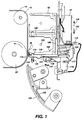
- FIG. 1 the transfer assist apparatus is depicted in an enlarged, elevational view to more clearly reveal the various components included therein.
- baffle members 132 and 134 direct a copy substrate (not shown) toward photoconductive belt 10 at transfer station D.
- Corona generating device 46 situated at the transfer station, includes a generally U-shaped shield, indicated generally by the reference numeral 102, partially surrounding an elongated electrode wire 104.
- Shield 102 has a back wall 106 and a pair of opposed, spaced side walls 108 and 110 secured thereto.
- corona generating device any suitable corona generating device may be employed, as for example, a corona generator having an electrode which is comprised of spaced pins, or a shield which may be limited to a pair of side walls having no back wall.
- the corona generating device 46 provides a means for charging the copy sheet at the transfer station to attract the toner powder image from the photoconductive belt 10 to the copy sheet.
- the transfer assist assembly includes a transfer assist blade 45 for pressing the sheet into intimate contact with the toner powder image on photoconductive belt 10.
- blade 45 is fabricated from a thin, flexible sheet material such as a polyester film which is elastically deformable to an arcuate shape.
- a polyester film which is elastically deformable to an arcuate shape.
- Mylar® available from E.I. DuPont de Nemours and Company of Wilmington, Delaware.
- a marginal region of blade 45 is removably secured to the free marginal end region of side wall 110 such that the opposite end of the blade protrudes beyond side wall 110 in the direction of the photoreceptor surface. In this way, blade 45 always exerts a force toward photoconductive belt 10 which must be opposed by end 116 of lever arm 114 to hold the blade away from the surface of the photoreceptor.
- a lever arm 114 is mounted adjacent to blade 45, having a free blade actuator end 116 which contacts blade 45 along the protruding segment thereof.
- the opposite end of lever arm 114 is secured via pivot arm 115 to a solenoid 47 which, in turn, is mounted to bracket 112 secured to back wall 106.
- Lever arm 114 is adapted to be pivoted along a central portion thereof about pivot pin 118 such that energization of solenoid 47, which pulls plunger 124 thereof in the direction of arrow 126, toward the body of the solenoid, operates to pivot lever arm 114 about point 118 in a counter clockwise direction as shown by arrow 130.
- lever arm 114 pivots about point 118, end 116 pivots in the direction of arrow 130, permitting blade 45 to flex or pivot toward the surface of the photoreceptor and into an operative position against the back of the copy sheet.
- the plunger 124 is caused to move in the direction of arrow 128, urged in that direction via return spring 117, such that free end 116 of lever arm 114 now pivots in the direction of arrow 122 causing blade 45 to be deflected away from the surface of the photoreceptor, to a non-operative position.
- baffles 132 and 134 guide the copy sheet into the transfer station.
- the controller transmits a signal to energize the solenoid or solenoids 47.
- Energization of the solenoid 47 translates plungers 124 in the direction of arrow 126, pivoting lever arm 114 about pivot point 118 such that the free end 116 of lever arm 114 pivots in the direction of arrow 130.
- blade 45 moves from the deflected, non-operative position to the undeflected, operative position, wherein the free end of blade 45 contacts the back of the copy sheet and presses the copy sheet against the developed toner powder image on photoconductive belt 10. This substantially eliminates any spaces between the copy sheet and the toner powder image substantially improving transfer of the toner powder image to the copy sheet.
- the toner powder image transferred to the copy sheet is substantially deletion free.
- a light sensor detects the trailing edge of the copy sheet, and, after a suitable delay, the controller transmits a deenergizing signal to the solenoid 47.
- De-energization of solenoid 47 causes end 116 of lever arm 114 to pivot in the direction of arrow 122. As end 116 pivots in the direction of arrow 122, it contacts blade 45 and deflects it from the operative position to the non-operative position.
- lever arm 114 pivots free end 116 in the direction of blade 45 to lift the blade away from the copy sheet on the photoconductive surface.
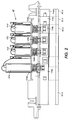
- lever arm 114 includes portions 114a, 114b, 114c and 114d.
- blade member 45 includes portions 45a, 45b, 45c and 45d.
- Solenoid 47 includes solenoid 47a having plunger 124a connected to lever arm 114a which acts on blade portion 45a, solenoid 47b having plunger 124b connected to lever arm 114b which acts on blade portion 45b, solenoid 47c having plunger 124c connected to lever arm 114c which acts on blade portion 45c and solenoid 47d having plunger 124d connected to lever arm 114d which acts on blade portion 45d.
- solenoid 47a moves blade portion 45a from the non-operative position to the operative position with blade portions 45b, 45c and 45d remaining at the non-operative position.
- This type of embodiment is used in machines capable of making copies on various sizes of copy sheets.
- the copy sheet is 8 1/2 ⁇ 11 inches, only solenoid 47a is energized, and only blade portion 45a moves from the non-operative position to the operative position.
- solenoids 47a, 47b, 47c and 47d are energized.
- solenoids 47a, 47b, 47c and 47d are energized.
- energization of selected solenoids moves corresponding blade portions from the non-operative position to the operative position.
- step signal for actuation and energization thereof is on the order of 60 ⁇ 20 msec for "pull in” and 45 ⁇ 20 msec for "push out". While the response time associated with the solenoids is sufficient to accommodate the maximum speed capabilities of the current model 5090 machine at 135 copies per minute, these response times are inadequate for meeting the increased copy speed outputs contemplated in future machines. For example, with machine speeds of 180 copies per minute, the transfer assist blade will be required to be lifted from the trail edge of a first copy sheet and subsequently contacted to a following copy sheet in a period of 24 msec. Clearly, this performance specification cannot be met using the present commercial embodiment.
- the present invention contemplates a solenoid actuated transfer assist apparatus as described, wherein the solenoid is driven by a dual voltage input signal for providing an overdrive voltage across the solenoid coil during initial actuation, followed by a transition to a minimal voltage drop across the solenoid coil sufficient for maintaining the solenoid in its energized state, a so called holding voltage.
- the concept of the present invention is implemented by substituting the 24 volt solenoid coils described above as being used in the prior art commercial embodiment, with solenoids having an 8 volt coil (model 121E11220 manufactured by Ledex, Inc. of Vandalia, Ohio) in combination with a driver circuit for providing an overdrive voltage across the solenoid coil for a predetermined time period during initial actuation of the solenoid, followed by a reduced minimal voltage drop across the solenoid coil sufficient for maintaining the solenoid in its energized state, the holding voltage.
- the driver circuit is shown schematically in Figure 3, wherein a solenoid energization signal from the machine controller provides an input signal to the dual voltage circuit at nodes 150 and 152.
- the input signal at node 150 provides a switching voltage to a level switching transistor circuit 160 while the input signal at node 152 provides a switching voltage to a level switching transistor circuit 162.
- a high gain Darlington driver (Q2) is utilized to provide a 24 volt overdrive spike to the solenoid coil (3 times the actual voltage specified for the coil) in response to an initial actuation signal at node 152, while a second driver transistor (Q1) is utilized to provide a 5 volt holding voltage (62.5% of the actual voltage specified for the coil) in response to a maintained energization signal at node 150.
- both drivers are energized upon solenoid actuation, wherein a diode (CR1) operates to prevent the 24 volt supply from interacting with the 5 volt supply.
- CR1 forward biasing of CR1 allows for uninterrupted current flow to the solenoid coil, thus preventing potential dropout during the transition from the 24 volt supply to the 5 volt supply.
- the blocking diode CR1 permits the elimination of mechanical turbulance as well as electrical switching noise during the tansition from high to low voltages.
- This dual voltage drive circuit yields a very low temperature rise in the solenoid due to the 5 volt holding voltage, while allowing the solenoid to pull in as low as 10 msec due to the 24 volt overdrive actuation voltage.
- the dual voltage driver circuit of Figure 3 uses independent control signals from the controller for both the 5 volt and the 24 volt sections of the dual voltage driver, permitting complete timing control via the machine programmable controller or other programmable means.
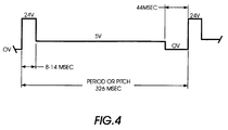
- Figure 4 shows a preferred output for the dual voltage driver circuit of Figure 3, wherein the time period between the entrance of lead edges for each copy sheet entering into the transfer station, or so called pitch, is 326 msec.
- the driver circuit provides a 24 volt DC output signal.
- the input signal to the overdrive circuit is removed such that the 24 volt supply is switched off while the 5 volt supply, biasing the diode (CR1), maintains the solenoid in an energized state, thereby holding the solenoid plunger in place. Thereafter, a 5 volt DC output signal is provided for all but the remaining approximately 44 msec of the pitch.
- the input signal to the hold voltage circuit is removed and the solenoid is deenergized by providing a 0 volt output from the driver circuit to permit the blade to be pushed away from the copy sheet, thereby preventing contact between the copy sheet and the photoreceptor during the time period between the departure of the trail edge of a first sheet from the transfer station and the subsequent entry of a lead edge of a second copy sheet into the transfer station.
- the output voltage signal shown in Figure 4 allows the solenoid to pull in in a time period as low as 10 msec., notwithstanding mechanical delays as well as the effects of tolerances in the mechanical and electrical systems associated with the transfer assist blade system.
- the solenoid response time is substantially reduced during the initial actuation while the temperature rise in the solenoid is also substantially reduced to minimize variability in the response time.
- the enhanced response time allows the transfer assist apparatus of the present invention to pull up from a trail edge and drop down on a lead edge in approximately 16 msec.
- the transfer apparatus of the present invention includes a blade member, normally spaced from the photoconductive surface, in the non-operative position, which is moved to an operative position for pressing the copy sheet into intimate contact with the toner powder image developed on the photoconductive belt by the action of a solenoid.
- a dual voltage driver circuit is utilized to substantially reduce the solenoid response time upon actuation while also minimizing variability of the response time by minimizing temperature increases in the solenoid during the period of energization.
- the shifting of the blade member from its operative to non-operative positions is controlled by a dual voltage drive solenoid apparatus which provides enhanced response time during initial actuation while reducing unwanted temperature increases and mechanical variability effects in the solenoid during the period of energization of the solenoid.
- the transfer assist blade system disclosed herein may include multiple segments which may be selectively moved to provide contact across the various widths of standard size copy sheets in a xerographic printing machine.
- the dual voltage circuit of the present invention may be advantageously utilized to drive other electrical devices such as stepper motors, clutches, rotary solenoids, motors and the like.
Landscapes
- Physics & Mathematics (AREA)
- General Physics & Mathematics (AREA)
- Electrostatic Charge, Transfer And Separation In Electrography (AREA)
- Control Or Security For Electrophotography (AREA)
Applications Claiming Priority (2)
| Application Number | Priority Date | Filing Date | Title |
|---|---|---|---|
| US55160195A | 1995-11-01 | 1995-11-01 | |
| US551601 | 1995-11-01 |
Publications (1)
| Publication Number | Publication Date |
|---|---|
| EP0772099A2 true EP0772099A2 (en) | 1997-05-07 |
Family
ID=24201938
Family Applications (1)
| Application Number | Title | Priority Date | Filing Date |
|---|---|---|---|
| EP19960307859 Withdrawn EP0772099A2 (en) | 1995-11-01 | 1996-10-30 | Dual voltage driven transfer assist apparatus |
Country Status (4)
| Country | Link |
|---|---|
| EP (1) | EP0772099A2 (es) |
| JP (1) | JPH09171308A (es) |
| BR (1) | BR9605348A (es) |
| MX (1) | MX9604841A (es) |
Families Citing this family (2)
| Publication number | Priority date | Publication date | Assignee | Title |
|---|---|---|---|---|
| JP4603428B2 (ja) * | 2005-06-17 | 2010-12-22 | 株式会社リコー | 画像形成装置および画像形成システム |
| JP4980674B2 (ja) | 2006-08-24 | 2012-07-18 | 株式会社リコー | 画像形成装置 |
Citations (3)
| Publication number | Priority date | Publication date | Assignee | Title |
|---|---|---|---|---|
| US4341456A (en) | 1980-06-27 | 1982-07-27 | Xerox Corporation | Transfer system for a xerographic reproduction machine |
| US4947214A (en) | 1989-01-10 | 1990-08-07 | Xerox Corporation | Transfer apparatus |
| US5081500A (en) | 1990-07-02 | 1992-01-14 | Xerox Corporation | Method and apparatus for using vibratory energy to reduce transfer deletions in electrophotographic imaging |
-
1996
- 1996-10-15 MX MX9604841A patent/MX9604841A/es unknown
- 1996-10-24 JP JP8299613A patent/JPH09171308A/ja not_active Withdrawn
- 1996-10-29 BR BR9605348A patent/BR9605348A/pt not_active Application Discontinuation
- 1996-10-30 EP EP19960307859 patent/EP0772099A2/en not_active Withdrawn
Patent Citations (3)
| Publication number | Priority date | Publication date | Assignee | Title |
|---|---|---|---|---|
| US4341456A (en) | 1980-06-27 | 1982-07-27 | Xerox Corporation | Transfer system for a xerographic reproduction machine |
| US4947214A (en) | 1989-01-10 | 1990-08-07 | Xerox Corporation | Transfer apparatus |
| US5081500A (en) | 1990-07-02 | 1992-01-14 | Xerox Corporation | Method and apparatus for using vibratory energy to reduce transfer deletions in electrophotographic imaging |
Also Published As
| Publication number | Publication date |
|---|---|
| JPH09171308A (ja) | 1997-06-30 |
| BR9605348A (pt) | 1998-07-28 |
| MX9604841A (es) | 1997-05-31 |
Similar Documents
| Publication | Publication Date | Title |
|---|---|---|
| JP2718559B2 (ja) | 印刷機 | |
| US5775690A (en) | Two step optimized stalled roll registration and deskew | |
| JP2897956B2 (ja) | 電子写真式印刷機 | |
| US5657983A (en) | Wear resistant registration edge guide | |
| US5568238A (en) | Transfer assist apparatus having a conductive blade member | |
| JP2008156121A (ja) | 媒体給送機及び給送方法 | |
| US4431301A (en) | Electrostatic copying apparatus with means for preventing contamination of reverse side of copying medium | |
| EP0622707B1 (en) | Transfer assist apparatus | |
| US5467182A (en) | Sheet transport for high productivity trayless duplex | |
| US6343686B1 (en) | Rotating clamp for changing the orientation of a substrate stack | |
| EP0869401B1 (en) | Method and apparatus for sheet jam clearance | |
| US5941518A (en) | Sheet feeder with variable length, variable speed sheetpath | |
| US5539508A (en) | Variable length transfer assist apparatus | |
| EP0361850A2 (en) | Sheet feeding and levelling apparatus | |
| US5300994A (en) | Transfer system including a cam actuated segmented flexible transfer assist blade | |
| JP4063942B2 (ja) | シートスキュー除去装置 | |
| US5337133A (en) | System to extend fuser roll life | |
| US6560428B2 (en) | Tensioning and detensioning assembly | |
| EP0772099A2 (en) | Dual voltage driven transfer assist apparatus | |
| JP3662332B2 (ja) | ロング・シートのデスキュ及びバックル長ラチチュードのためのカム・アイドラ | |
| US5549291A (en) | Printer with multiple-sized sheets duplex tray assembly | |
| JP3824703B2 (ja) | クリージングを防止するために失速ロール・レジストレーション・サブシステムにおける円錐状駆動ロールの使用 | |
| JP2809423B2 (ja) | 複写機の転写装置 | |
| US4751547A (en) | Sheet guide | |
| EP0848300B1 (en) | Simplex printing with duplex printer |
Legal Events
| Date | Code | Title | Description |
|---|---|---|---|
| PUAI | Public reference made under article 153(3) epc to a published international application that has entered the european phase |
Free format text: ORIGINAL CODE: 0009012 |
|
| AK | Designated contracting states |
Kind code of ref document: A2 Designated state(s): DE FR GB |
|
| STAA | Information on the status of an ep patent application or granted ep patent |
Free format text: STATUS: THE APPLICATION HAS BEEN WITHDRAWN |
|
| 18W | Application withdrawn |
Withdrawal date: 19990414 |