EP0772003A1 - Device for drawing off a gas through a conduit for venting it - Google Patents
Device for drawing off a gas through a conduit for venting it Download PDFInfo
- Publication number
- EP0772003A1 EP0772003A1 EP96402337A EP96402337A EP0772003A1 EP 0772003 A1 EP0772003 A1 EP 0772003A1 EP 96402337 A EP96402337 A EP 96402337A EP 96402337 A EP96402337 A EP 96402337A EP 0772003 A1 EP0772003 A1 EP 0772003A1
- Authority
- EP
- European Patent Office
- Prior art keywords
- nozzles
- section
- duct
- gaseous
- injection
- Prior art date
- Legal status (The legal status is an assumption and is not a legal conclusion. Google has not performed a legal analysis and makes no representation as to the accuracy of the status listed.)
- Granted
Links
- 238000013022 venting Methods 0.000 title 1
- 230000003068 static effect Effects 0.000 claims abstract description 54
- 239000012530 fluid Substances 0.000 claims description 87
- 238000002347 injection Methods 0.000 claims description 76
- 239000007924 injection Substances 0.000 claims description 76
- 238000011144 upstream manufacturing Methods 0.000 claims description 17
- 230000002093 peripheral effect Effects 0.000 claims description 15
- 238000009434 installation Methods 0.000 claims description 11
- 238000009423 ventilation Methods 0.000 claims description 10
- 230000004323 axial length Effects 0.000 claims description 8
- 239000007789 gas Substances 0.000 claims description 8
- 238000002485 combustion reaction Methods 0.000 claims description 7
- 239000003570 air Substances 0.000 claims description 6
- 239000003517 fume Substances 0.000 claims description 6
- 239000000523 sample Substances 0.000 claims description 6
- 125000006850 spacer group Chemical group 0.000 claims description 5
- 238000006073 displacement reaction Methods 0.000 claims description 3
- 230000002706 hydrostatic effect Effects 0.000 claims description 3
- 238000003466 welding Methods 0.000 claims description 3
- 239000000047 product Substances 0.000 claims description 2
- 238000007599 discharging Methods 0.000 claims 2
- 238000007664 blowing Methods 0.000 description 2
- 238000000605 extraction Methods 0.000 description 2
- 230000003213 activating effect Effects 0.000 description 1
- 230000000295 complement effect Effects 0.000 description 1
- 238000010276 construction Methods 0.000 description 1
- 239000000779 smoke Substances 0.000 description 1
Images


Classifications
-
- F—MECHANICAL ENGINEERING; LIGHTING; HEATING; WEAPONS; BLASTING
- F23—COMBUSTION APPARATUS; COMBUSTION PROCESSES
- F23L—SUPPLYING AIR OR NON-COMBUSTIBLE LIQUIDS OR GASES TO COMBUSTION APPARATUS IN GENERAL ; VALVES OR DAMPERS SPECIALLY ADAPTED FOR CONTROLLING AIR SUPPLY OR DRAUGHT IN COMBUSTION APPARATUS; INDUCING DRAUGHT IN COMBUSTION APPARATUS; TOPS FOR CHIMNEYS OR VENTILATING SHAFTS; TERMINALS FOR FLUES
- F23L17/00—Inducing draught; Tops for chimneys or ventilating shafts; Terminals for flues
- F23L17/16—Induction apparatus, e.g. steam jet, acting on combustion products beyond the fire
-
- F—MECHANICAL ENGINEERING; LIGHTING; HEATING; WEAPONS; BLASTING
- F23—COMBUSTION APPARATUS; COMBUSTION PROCESSES
- F23L—SUPPLYING AIR OR NON-COMBUSTIBLE LIQUIDS OR GASES TO COMBUSTION APPARATUS IN GENERAL ; VALVES OR DAMPERS SPECIALLY ADAPTED FOR CONTROLLING AIR SUPPLY OR DRAUGHT IN COMBUSTION APPARATUS; INDUCING DRAUGHT IN COMBUSTION APPARATUS; TOPS FOR CHIMNEYS OR VENTILATING SHAFTS; TERMINALS FOR FLUES
- F23L17/00—Inducing draught; Tops for chimneys or ventilating shafts; Terminals for flues
- F23L17/005—Inducing draught; Tops for chimneys or ventilating shafts; Terminals for flues using fans
-
- F—MECHANICAL ENGINEERING; LIGHTING; HEATING; WEAPONS; BLASTING
- F23—COMBUSTION APPARATUS; COMBUSTION PROCESSES
- F23L—SUPPLYING AIR OR NON-COMBUSTIBLE LIQUIDS OR GASES TO COMBUSTION APPARATUS IN GENERAL ; VALVES OR DAMPERS SPECIALLY ADAPTED FOR CONTROLLING AIR SUPPLY OR DRAUGHT IN COMBUSTION APPARATUS; INDUCING DRAUGHT IN COMBUSTION APPARATUS; TOPS FOR CHIMNEYS OR VENTILATING SHAFTS; TERMINALS FOR FLUES
- F23L17/00—Inducing draught; Tops for chimneys or ventilating shafts; Terminals for flues
- F23L17/02—Tops for chimneys or ventilating shafts; Terminals for flues
- F23L17/08—Tops for chimneys or ventilating shafts; Terminals for flues with coaxial cones or louvres
-
- F—MECHANICAL ENGINEERING; LIGHTING; HEATING; WEAPONS; BLASTING
- F24—HEATING; RANGES; VENTILATING
- F24F—AIR-CONDITIONING; AIR-HUMIDIFICATION; VENTILATION; USE OF AIR CURRENTS FOR SCREENING
- F24F7/00—Ventilation
- F24F7/02—Roof ventilation
- F24F7/025—Roof ventilation with forced air circulation by means of a built-in ventilator
Definitions
- the invention relates to a device for sucking a gaseous fluid through a main duct to discharge it outside, intended for the evacuation of ventilation air, gases, fumes, products of combustion from industrial, work, residential or other premises.
- the invention also relates to an installation comprising such a device.
- a device for activating the ventilation of an air extraction duct including a medium-pressure blown air nozzle located either in the axis of the duct. , either laterally depending on whether it is a question of increasing or slowing down the extracted air flow.
- a static extractor is defined as being a “device without moving parts intended to be installed on top of ventilation or smoke ducts, having the objective, by creating a depression as a function of the wind speed, of opposing reversals of circulation of air flows and to increase the extracted flows in the presence of wind.
- static mechanical extractors as "static extractors equipped with a complementary device using an energy source other than that of the wind”.
- the object of the invention is to further improve the draft, whether it is natural or improved as a result of the presence of a static or stato-mechanical vacuum cleaner.
- the invention also aims to obtain this result without substantially increasing the complexity of the device used.
- the invention relates to a device for sucking a gaseous fluid through a main duct to discharge it outside thereof, intended for the evacuation of ventilation air, gases, fumes, combustion from industrial, working, residential or other premises, which comprises, in combination, in the first place, a section of duct, essentially straight, of a certain axial length, intended to be downstream of the main duct by relation to the direction of circulation of the gaseous fluid to be discharged and, secondly, means of injecting a gaseous driving fluid into the section of conduit, in the same direction as the direction of circulation of the gaseous fluid to be discharged, intended to be associated with means for producing the drive of said gaseous drive fluid, located at a certain distance upstream from the downstream end of the section of pipe as a function of the length of the main pipe, so that the spacing is on the one hand between 0.1 and 20% of the length of the main duct and more particularly of the order of 10% and, on the other hand, between 50 cm and 2 m,
- the invention relates to a device for sucking a gaseous fluid through a main conduit to discharge it outside of it which comprises, in combination, firstly, the section of conduit previously mentioned, in second, a static or statomechanical vacuum cleaner mounted on the section of conduit at its downstream end and, thirdly, means for injecting a gaseous drive fluid into the pipe section and through the static or statomechanical vacuum cleaner, in the same direction as the direction of circulation of the gaseous fluid to be discharged, intended to be associated with means for producing or driving said gaseous drive fluid, located at a certain distance upstream from the downstream end of the duct section and from the static or statomechanical vacuum cleaner.
- the static or stato-mechanical vacuum cleaner it is of the type comprising a lower part and an upper part spaced from one another and rigidly associated with each other along the axis of the section of conduit, the lower part being provided with a hole for the passage of the gaseous fluid to be discharged and the gaseous drive fluid, in communication with the section of conduit, this hole opening into the space existing between the lower part and the upper part.
- the space between the lower and upper parts has in axial section a general form of venturi.
- the static or stato-mechanical vacuum cleaner has a general shape of revolution whose axis is in the extension of that of the duct section or slightly inclined with respect to it.
- the lower part of the static or statomechanical vacuum cleaner comprises at least one upper wall of generally frustoconical shape, the small base of which faces the upper part and the large base of which faces the duct section.
- the lower part of the static or statomechanical vacuum cleaner also comprises a lower wall of generally frustoconical shape, the small base of which faces the duct section and the large base towards the upper wall of said lower part.
- the upper part of the static or statomechanical vacuum cleaner comprises at least one lower wall of generally conical or frustoconical shape, the point or the small base of which faces the lower part and the large base opposite the section of duct.
- the upper part of the static or statomechanical vacuum cleaner also comprises an upper wall of generally conical or frustoconical or hemispherical shape, the large base of which faces the lower wall of said upper part.
- the upper part and the lower part have substantially the same outside diameter.
- the static or stato-mechanical vacuum cleaner includes spacers for reciprocal attachment of the two lower and upper parts, associated in particular with the upper wall of the lower part and with the lower wall of the upper part.
- the constitutive walls of the lower and upper parts of the static or stato-mechanical vacuum cleaner are full, devoid of openings.
- the static or stato-mechanical vacuum cleaner also has a ferrule adjoining the lower part, intended for fixing the vacuum cleaner to the duct section.
- the vacuum cleaner is static and has no moving parts, in particular no integrated turbine.
- the vacuum cleaner is stato-mechanical and it also includes, for this purpose, an integrated turbine.
- Such a turbine has its blades located in the space existing between the lower and upper parts or that formed by the upper part.
- the section of conduit is either distinct from the main conduit and rigidly associated with it by bolting, welding, strapping or other, or it forms a single piece with it, the section of conduit forming the downstream end portion of the main conduit.
- the duct section can be an integral part of the static or statomechanical vacuum cleaner by being constituted by the ferrule with which the latter is provided, the latter having an axial length sufficient to allow mounting on the main duct. .
- the pipe section and the main pipe have the same diameter or substantially the same diameter. They are coaxial or their respective axes are slightly inclined relative to each other.
- these means comprise one or more injection nozzles or equivalent located inside the section of pipe and carried by it and one or more pipes injection, in communication with the nozzle (s), essentially located outside the pipe section as well as the main pipe.
- This or these injection conduits are located essentially upstream of the nozzles.
- the injection nozzle (s) have a generally fixed position in the pipe section, at least as regards their spacing with respect to the axis of the pipe section.
- injection nozzles arranged in different places of the duct section, in the axis and / or spaced from it.
- the plurality of injection nozzles is located substantially in the same transverse plane of the duct section or in several transverse planes of the duct section. In this case, the latter include an upstream plane and a downstream plane.
- this plurality comprises one or more central nozzles located in or near the axis of the duct section and / or a plurality of peripheral nozzles located near the wall of the duct section and / or a plurality of median nozzles located between the axis of the duct section and its wall.
- the peripheral and / or median nozzles are regularly distributed around the axis of the duct section.
- the different injection nozzles are arranged in relation to each other so as not to substantially obstruct the passage of the gaseous fluid to be discharged coming from upstream of the nozzles through the main conduit.
- the injection nozzles are arranged in rows and columns carried by a perforated plate located in the section of duct and carried by it.
- the device comprises a plurality of injection nozzles or equivalent
- the physical characteristics such as, in particular, flow rate, speed and opening of the beam of the flow of gaseous drive fluid injected by the different nozzles are identical or similar.
- these physical characteristics are differentiated between the nozzles according to the requirements required.
- the device comprises means for adjusting the physical characteristics in question for the different injection nozzles or over time.
- the spacing between the different nozzles and the downstream end of the duct section or the static or statomechanical vacuum cleaner is identical or differentiated according to the nozzles according to the requirements required.
- At least one or some nozzles are mounted slidingly adjustable parallel to the axis of the section of conduit between two extreme positions, respectively distal and proximal.
- the device comprises sliding guide means of the adjustable sliding nozzle (s), means for driving the nozzles and means for controlling the driving means.
- the space located downstream of the injection nozzles is free or, on the contrary, one or more walls in the form of a venturi are provided at this location.
- the device may include a wall in the form of a venturi adjoining the wall of the section of conduit. or / and a wall in the form of a venturi for one or more injection nozzles, in particular of the same kind, central, peripheral or median.
- an injection nozzle is chosen to provide an injection flow in the form of a narrow beam or of a wide beam, or of a spiral jet.
- An injection nozzle is either of fixed axis, in particular parallel to the axis of the duct section or inclined thereon, or of displaceable axis, the device then being provided with means for moving the axis of the displaceable nozzles and of means for controlling the displacement means.
- the device also comprises means for modulating the flow rate and / or the speed of the flow of gaseous drive fluid as a function of the requirements required.
- modulation means include means for controlling the triggering of the injection of gaseous drive fluid such as clock, temperature probe, pressure switch, hydrostatic probe.
- the invention also relates to an installation comprising one or more main conduits, one or more devices as described above and means for producing and driving the gaseous drive fluid.
- the means for producing and driving a gaseous drive fluid can be common to several conduits and they can be separated from the suction and drive device (s).
- FIG. 1 is a purely schematic view of an installation comprising a device according to the invention.
- Figures 2a to 2k are eleven partial schematic figures illustrating several embodiments of the means for injecting a gaseous drive fluid.
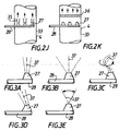
- Figures 3a to 3e are five schematic views, on a larger scale, illustrating different alternative embodiments of nozzles or the like of said injection means.
- the invention relates to a device 1 for sucking a gaseous fluid through a main conduit 2 to discharge it outside thereof.
- Such a device 1 is intended more specifically for the evacuation of ventilation air, gases, fumes, combustion products from industrial, work, residential or other premises.
- Such a device alone or associated with other similar ones, can be incorporated in an installation comprising one or more main duct (s) such as 2.
- Such an installation also includes means 3 for producing and driving a gaseous drive fluid.
- the means 3 for producing and driving a gaseous driving fluid can be separated from the device (s) 1.
- the main duct (s) 2 are generally arranged vertically and the device (s) 1 placed at the top of these.
- the means 3 for producing, for driving gaseous driving fluid are preferably placed on the ground, or even in the basement.
- the device 1 comprises in combination, in the first place, a section of conduit 4 of axis 4a, essentially rectilinear, of a certain axial length.
- the pipe section 4 is intended to be downstream of the main pipe 2 of axis 2a, relative to the direction of circulation of the gaseous fluid to be discharged.
- the pipe section 4 is associated with the end part 5 of the pipe 2.
- the main conduit 2 has one or more inlets 6 for the gaseous fluid to be discharged.
- the main duct 2 extends over a certain axial length, and there are provided several inlets 6 spaced along the axis 2a corresponding for example to different floors of the building for which the device 1 is intended and the installation that incorporates it.
- the main duct can, if necessary, be doubled with a duct which adjoins it, corresponding to a last floor of the building.
- the inlets 6 can be associated with horizontal ducts in which the nozzles for injecting gaseous fluid are also mounted.
- the device 1 comprises, in the embodiment shown in Figure 1, secondly, a static vacuum cleaner 7 shown purely schematically.
- This static vacuum cleaner 7 is mounted on the duct section 4 at its downstream end with respect to the direction of circulation of the gaseous fluids to be discharged and of drive. This means that the static vacuum cleaner 7 is, in the embodiment more especially considered, located in part upper end of the 4 in the upper extreme part of the duct section 4.
- the static vacuum cleaner 7 can be of the statomechanical type rather than static.
- the device 1 also comprises, thirdly, means 8 for injecting a gaseous drive fluid into the section of conduit 4 in the same direction as the direction of circulation of the gaseous fluid to be discharged.
- the injection means 8 are intended to be associated with the means 3 for producing and driving the gaseous drive fluid.
- the injection means 8 are located being spaced a certain distance upstream from the downstream end 9 of the section of conduit 4.
- the injection means 8 also inject a gaseous drive fluid through the static aspirator 7 or statomechanical.
- the injection means 8 are also spaced from said static or stato-mechanical vacuum cleaner 7.
- the pipe section 4 is associated by its upstream end 10 with the upper end part 5 of the main pipe 2.
- the spacing between the injection means 8 and the downstream end 9 of the pipe section 4 is a function in particular of the length of the main pipe 2.
- the spacing between the injection means 8 and the downstream end 9 of the pipe section 4 is between 0.1 and 20% of the length of the main pipe 2 and more specifically, is of the order of 10% this length.
- this spacing is between 50 cm and 2 m, more particularly between 75 cm and 1.25 m. It is more particularly of the order of 1 m.
- the length of the main duct 2 to which reference is made is the so-called useful length, that is to say that which extends between the most extreme lower inlet 6 (i.e. say the most removed from the device 1) and the device 1 in question, respectively the vacuum cleaner 7.
- the means 8 for injecting the gaseous driving fluid as well as the means 3 for producing and driving said gaseous fluid are designed and arranged to be able to allow on the one hand a flow of gaseous driving fluid between 20 and 100% of the nominal flow rate of gaseous fluid in the main duct 2 and more especially between 20 and 60% and, on the other hand, a speed of the gaseous drive fluid between 10 and 100 m / s, and more especially between 20 and 60 m / s, this for the applications considered.
- one or more sections 4 may be provided, depending on the embodiments envisaged. Consequently, the means 8 are themselves single or multiple.
- a static vacuum cleaner such as 7 or a static mechanical vacuum cleaner can be the subject of numerous variant embodiments.
- a static mechanical vacuum cleaner is more specifically described in the following documents also incorporated in the present description.
- a static vacuum cleaner 7 will therefore now be described, more particularly with reference to FIG. 1.
- the static vacuum cleaner 7 is of the type comprising a lower part 11, an upper part 12 coaxial with axis 13, of revolution about this axis, and the outside diameter of which is identical or substantially the same.
- the two lower parts 11 and upper 12 are spaced from one another to provide between them a free space 14 having in axial section a general shape of venturi.
- the lower 11 and upper 12 parts are rigidly associated with one another by means of reciprocal securing spacers 15.
- these spacers 15 are in the form of flat sections, these are radial planes to avoid excessive wind resistance.
- the duct section 4 can form a diffuser in the lower part 11.
- there can be a cross.
- the axis 13 is coaxial with the axis 4a. In other embodiments not shown, the axis 13 can be slightly inclined relative to the axis 4a and relative to the vertical.
- the lower part 11 comprises, in the embodiment shown, an upper wall 17 and a lower wall 18.
- Both the upper wall 17 and the lower wall 18 have a generally frustoconical shape.
- the small base 19 of the upper wall 17 is turned towards the upper part 12 and the space 14.
- the large base 20 of the upper wall 17 faces the duct section 4 and it is common with the large base of the wall lower 18 whose small base is turned towards 4 whose small base is turned towards the duct section 4.
- the upper part 12 has a lower wall 21 and an upper wall 22.
- the bottom wall 21 has, in the embodiment shown, a generally conical shape. In another possible embodiment, the bottom wall 21 has a generally frustoconical shape. In one as in the other of the possible embodiments, the point 23 or the small base of the lower wall 21 is turned towards the lower part 12, that is to say towards the space 14. The large base 24 is in turn opposite to the section of conduit 4.
- the upper wall 22 has, in the embodiment shown, a generally conical shape. In other embodiments, the upper wall 22 has a generally frustoconical or hemispherical shape, or a complex shape derived from the preceding shapes.
- the upper wall 22 has a large base common with the large base 24. It therefore faces the lower part 11.
- the spacers 15 already mentioned are for example associated with the upper wall 17 of the lower part 11 and with the lower wall 21 of the upper part 12.
- the vacuum cleaner 7 shown is of the static type, it also comes within the scope of the present invention that this vacuum cleaner is of the stato-mechanical type. In this case (not shown), the vacuum cleaner 7 also includes an integrated turbine.
- This turbine has its blades located in the space 14 or in a space provided by the upper part 12.
- the vacuum cleaner 7 also includes a ferrule 25 adjoining the lower part 11, intended for fixing the vacuum cleaner 7 to the duct section 4.
- the pipe section 4 is separate from the main pipe 2, but rigidly associated with it by bolting, welding, strapping or the like.
- the upstream end 10 of the pipe section 4 comes into an enlarged part ending in a shoulder of the upper end part 5 of the pipe 2.
- Appropriate fixing means 26 such as a clamp, bolts, etc., ensure the rigid association of the two conduits 2, 4 where they overlap.
- the vacuum cleaner includes a ferrule 25
- this can also be widened and form a shoulder for the downstream end 9 of the duct section 4.
- the association of the ferrule 25 and the duct section 4, for their joining can be ensured by fixing means such as the means 26 already mentioned.
- the duct section 4 is an integral part of the static or statomechanical vacuum cleaner 7.
- the duct section 4 is then constituted by the ferrule 25 which is provided with the vacuum cleaner 7.
- This ferrule 25 then has an axial length sufficient to allow it to be mounted on the main duct 2.
- the main pipe 2 and the section of pipe 4 form a single piece.
- the pipe section 4 forms the downstream end part of the main pipe 2.
- conduits 2 and 4 have the same diameter or substantially the same diameter. They are also coaxial or their respective axes 2a, 4a are slightly inclined relative to each other.
- the injection means 8 are now more specifically described.
- These means 8 comprise one or more injection nozzles or equivalent 27 located inside the duct section 4 and carried by it, and one or more injection conduits 28, in communication with the nozzle (s) 27, essentially located outside the pipe section 4, as well as the main pipe 2.
- the injection nozzles or equivalent 27 are located at or near the upstream end 10 of the pipe section 4 and are carried by the conduit 28 which passes through the peripheral wall of the section 4, thus being fixed to it.
- the nozzles 27 are carried by the duct (s) 28 and therefore carried indirectly by the section of duct 4.
- the duct (s) 28 open out in this embodiment, perpendicularly to the outside of the duct 4. Subsequently, the duct (s) 28 may be shaped in an appropriate manner to join the means 3 for producing and driving the gaseous driving fluid.
- the injection pipe or pipes 28 are situated essentially upstream of the nozzles 27 so as not to hinder the flow of gaseous drive fluid coming from the latter.
- the injection nozzle (s) 27 or equivalent have a generally fixed position in the section of conduit 4, at least as regards their spacing with respect to the axis 4a of said section of conduit 4 .
- At least one or some nozzles are mounted adjustable by sliding parallel to this axis 4a between two extreme positions respectively distal and proximal.
- FIG. 2e Such an embodiment is more particularly represented in FIG. 2e where the distal position is represented in solid lines, while the proximal position is represented in dashes.
- the device comprises sliding guide means for the injection nozzle or nozzles 27 or equivalent, which are adjustable by sliding.
- the device also comprises means for driving the nozzles and means for controlling said driving means.
- the nozzles can be mounted on sections of pipes slidably mounted one inside the other.
- the nozzles can be carried by a system such as a deformable parallelogram while being joined to the injection pipe 28 by flexible pipes.
- a single, central injection nozzle situated in the axis or substantially in the axis of the section of conduit 4.
- a plurality of nozzles is provided injection located in the immediate vicinity of this axis 4a as shown in Figure 2d.
- injection nozzles 27 or equivalent arranged in different places of the section of conduit 4, in the axis 4a and / or removed from it.
- This plurality of injection nozzles 27 or equivalent is located substantially either in the same transverse plane of the duct section 4, as shown in FIGS. 2b or 2f, or in several transverse planes, as shown in Figures 2c and 2g.
- the transverse nozzle planes comprise an upstream plane 29 and a downstream plane 30.
- the upstream plane 29 there is one or more central nozzles or peripheral nozzles.
- peripheral nozzles In the downstream plane 30, there are peripheral nozzles, or one or more central nozzles.
- this plurality comprises one or more central nozzles 31 located in or near the axis 4a and / or one or more peripheral nozzles 32 located near the wall 33 of the duct section 4 and / or a plurality of median nozzles 34 located between the axis 4) and the wall 33.
- peripheral nozzles 32 and median nozzles 34 are, in one embodiment, regularly distributed around the axis 4a, either discretely or continuously.
- these nozzles 32, 34 can be arranged in the form of a crown.
- the different nozzles 27, 31, 32, 34 are arranged with respect to one another so as not to substantially obstruct the passage of the gaseous fluid to be discharged which comes from upstream of the section of duct 4 and of the main duct 2 Indeed, it is desirable that the flow of gaseous fluid to be discharged is not too disturbed by the presence of the injection nozzles.
- the injection nozzles 27 are arranged in rows and columns and are carried by a perforated plate located in the section of conduit 4 being carried by it.
- This plate is either flat ( Figure 2f) or curved ( Figure 2g).
- the device 1 generally comprises means for selective control of the operation of the different nozzles. In fact, it is not necessarily compulsory that all the nozzles operate continuously and in the same way.
- the physical characteristics of the flow of gaseous drive fluid injected by the different nozzles 27 such as flow rate, speed or opening of the beam are identical or similar.
- the flow rate and the speed may be greater for a central nozzle 31 than for a peripheral nozzle 32.
- the device may include means for adjusting these physical characteristics.
- the spacing between the different injection nozzles 27 and the downstream end 9 of the duct section 4 or the vacuum cleaner 7 is either identical or differentiated according to the nozzles 27 according to the requirements required for proper operation.
- This spacing is either constant over time or variable.
- one or some nozzles are mounted sliding adjustable parallel to the axis 4a as has already been described.
- the space located downstream of the nozzles is free.
- one or more wall 35 in the form of a venturi can be provided placed downstream of the injection nozzles 27 and associated with them.
- FIG. 2k there may be provided in the section of conduit 4, downstream of the nozzles 27, a diffuser such as 36 allowing the gaseous drive fluid to have an appropriate laminar flow.
- injection nozzles 27 or equivalent can also be the subject of different variant embodiments.
- an injection nozzle 27 or equivalent can be chosen to provide an injection flow in the form of a narrow beam (FIG. 3a) or in the form of a wide beam (FIG. 3b) or even in the form of a spiral jet (FIG. 3c).
- the axis 37 of the flow of gaseous drive fluid from a nozzle 27 can be either fixed ( Figures 3a, 3b, 3d), or movable. In the first case, this axis is either parallel to axis 4a ( Figures 3a, 3b), or inclined relative to it ( Figure 3d). In the second case ( Figure 3e), the device is provided with means for moving the axis of the displaceable nozzles and means for controlling these displacement means.
- the device 1 also comprises means for modulating the flow rate and / or the speed of the flow of gaseous drive fluid as a function of the required requirements.
- modulation means include in particular means for controlling the triggering of the injection of the gaseous drive fluid such as clock, temperature probe, pressure switch or hydrostatic probe.
Landscapes
- Engineering & Computer Science (AREA)
- Chemical & Material Sciences (AREA)
- Combustion & Propulsion (AREA)
- Mechanical Engineering (AREA)
- General Engineering & Computer Science (AREA)
- Jet Pumps And Other Pumps (AREA)
- Sampling And Sample Adjustment (AREA)
- Electrical Discharge Machining, Electrochemical Machining, And Combined Machining (AREA)
Abstract
Description
L'invention concerne un dispositif pour aspirer un fluide gazeux à travers un conduit principal pour le rejeter à l'extérieur de celui-ci, destiné à l'évacuation de l'air de ventilation, des gaz, des fumées, des produits de combustion en provenance de locaux industriels, de travail, d'habitation ou autres. L'invention concerne également une installation comportant un tel dispositif.The invention relates to a device for sucking a gaseous fluid through a main duct to discharge it outside, intended for the evacuation of ventilation air, gases, fumes, products of combustion from industrial, work, residential or other premises. The invention also relates to an installation comprising such a device.
On connaît déjà, de longue date, l'injection d'un jet d'air en sommet d'un conduit de tirage naturel. Un tel principe a été mis en oeuvre il y a de nombreuses années pour la ventilation des cales de navires et pour les brûleurs des cuisinières à gaz.We have already known, for a long time, the injection of an air jet at the top of a natural draft duct. Such a principle was implemented many years ago for the ventilation of ship's holds and for the burners of gas stoves.
Selon le document EP-A-329 498, il est prévu un dispositif d'activation de la ventilation d'une gaine d'extraction d'air incluant une buse d'air soufflé à moyenne pression se trouvant soit dans l'axe du conduit, soit latéralement selon qu'il s'agit d'augmenter ou de ralentir le débit d'air extrait.According to document EP-A-329 498, there is provided a device for activating the ventilation of an air extraction duct including a medium-pressure blown air nozzle located either in the axis of the duct. , either laterally depending on whether it is a question of increasing or slowing down the extracted air flow.
Selon le document DE-A-2 647 126, il est prévu d'insuffler de l'air au-dessus du conduit mais non à l'intérieur de celui-ci.According to document DE-A-2,647,126, provision is made for blowing air above the duct but not inside it.
Selon le document FR-A-2 658 271, il est prévu d'insuffler de l'air directement dans un aspirateur statique.According to document FR-A-2 658 271, provision is made for blowing air directly into a static vacuum cleaner.
Selon un guide intitulé "Systèmes de ventilation et d'évacuation des produits de combustion du gaz à tirage naturel pour l'habitat collectif réhabilité" établi par Gaz de France, un extracteur statique est défini comme étant un "appareil sans pièces mobiles destiné à être installé en couronnement de conduits de ventilation ou de fumée, ayant pour objectif, en créant une dépression en fonction de la vitesse du vent, de s'opposer à des inversions de circulation des flux d'air et d'augmenter les débits extraits en présence de vent."According to a guide entitled "Ventilation and evacuation systems of natural draft gas combustion products for rehabilitated collective housing" established by Gaz de France, a static extractor is defined as being a "device without moving parts intended to be installed on top of ventilation or smoke ducts, having the objective, by creating a depression as a function of the wind speed, of opposing reversals of circulation of air flows and to increase the extracted flows in the presence of wind. "
Le même guide définit les extracteurs stato-mécaniques comme étant des "extracteurs statiques équipés d'un dispositif complémentaire utilisant une source d'énergie autre que celle du vent".The same guide defines static mechanical extractors as "static extractors equipped with a complementary device using an energy source other than that of the wind".
Qu'ils soient statiques ou stato-mécaniques, de tels extracteurs sont également dénommés "aspirateurs".Whether static or stato-mechanical, such extractors are also called "vacuum cleaners".
Des exemples de réalisation de tels aspirateurs statiques ou stato-mécaniques sont illustrés notamment par les documents suivants : FR-A-2 658 271, FR-A-2 651 563, FR-A-2 709 533, FR-A-2 374 591, FR-A-2 438 795, FR-A-2 514 469, FR-A-2 518 710, FR-A-2 034 434.Examples of embodiment of such static or stato-mechanical vacuum cleaners are illustrated in particular by the following documents: FR-A-2 658 271, FR-A-2 651 563, FR-A-2 709 533, FR-A-2 374 591, FR-A-2 438 795, FR-A-2 514 469, FR-A-2 518 710, FR-A-2 034 434.
Le but de l'invention est d'améliorer encore le tirage, que celui-ci soit naturel ou amélioré par suite de la présence d'un aspirateur statique ou stato-mécanique.The object of the invention is to further improve the draft, whether it is natural or improved as a result of the presence of a static or stato-mechanical vacuum cleaner.
L'invention a également pour but d'obtenir ce résultat sans augmenter substantiellement la complexité du dispositif mis en oeuvre.The invention also aims to obtain this result without substantially increasing the complexity of the device used.
A cet effet et selon un premier aspect, l'invention concerne un dispositif pour aspirer un fluide gazeux à travers un conduit principal pour le rejeter à l'extérieur de celui-ci, destiné à l'évacuation de l'air de ventilation, des gaz, des fumées, des produits de combustion en provenance de locaux industriels, de travail, d'habitation ou autres, qui comporte, en combinaison, en premier lieu, un tronçon de conduit, essentiellement rectiligne, d'une certaine longueur axiale, destiné à être en aval du conduit principal par rapport au sens de circulation du fluide gazeux à rejeter et, en second lieu, des moyens d'injection d'un fluide gazeux d'entraînement dans le tronçon de conduit, dans le même sens que le sens de circulation du fluide gazeux à rejeter, destinés à être associés à des moyens de production d'entraînement dudit fluide gazeux d'entraînement, situés écartés à une certaine distance en amont de l'extrémité aval du tronçon de conduit en fonction de la longueur du conduit principal, de manière que l'écartement soit compris d'une part entre 0,1 et 20 % de la longueur du conduit principal et plus spécialement de l'ordre de 10 % et, d'autre part, entre 50 cm et 2 m, plus spécialement entre 75 cm et 1,25 m, et plus spécialement de l'ordre de 1 m ; les moyens d'injection du fluide gazeux d'entraînement ainsi que les moyens de production, d'entraînement dudit fluide gazeux d'entraînement étant aptes à permettre d'une part un débit de fluide gazeux d'entraînement compris entre 20 et 100 % du débit nominal de fluide gazeux dans le conduit principal et plus spécialement entre 20 et 60 % et, d'autre part, une vitesse du fluide gazeux d'entraînement comprise entre 10 et 100 m/s, et plus spécialement entre 20 et 60 m/s.To this end and according to a first aspect, the invention relates to a device for sucking a gaseous fluid through a main duct to discharge it outside thereof, intended for the evacuation of ventilation air, gases, fumes, combustion from industrial, working, residential or other premises, which comprises, in combination, in the first place, a section of duct, essentially straight, of a certain axial length, intended to be downstream of the main duct by relation to the direction of circulation of the gaseous fluid to be discharged and, secondly, means of injecting a gaseous driving fluid into the section of conduit, in the same direction as the direction of circulation of the gaseous fluid to be discharged, intended to be associated with means for producing the drive of said gaseous drive fluid, located at a certain distance upstream from the downstream end of the section of pipe as a function of the length of the main pipe, so that the spacing is on the one hand between 0.1 and 20% of the length of the main duct and more particularly of the order of 10% and, on the other hand, between 50 cm and 2 m, more especially between 75 cm and 1.25 m, and more especially of the order of 1 m; the means for injecting the gaseous drive fluid as well as the means for producing and driving said gaseous drive fluid being capable of allowing, on the one hand, a flow rate of gaseous drive fluid between 20 and 100% of the nominal flow rate of gaseous fluid in the main conduit and more particularly between 20 and 60% and, on the other hand, a speed of the gaseous drive fluid of between 10 and 100 m / s, and more especially between 20 and 60 m / s.
Selon un autre aspect, l'invention concerne un dispositif pour aspirer un fluide gazeux à travers un conduit principal pour le rejeter à l'extérieur de celui-ci qui comporte, en combinaison, en premier lieu, le tronçon de conduit précédemment mentionné, en deuxième lieu, un aspirateur statique ou stato-mécanique monté sur le tronçon de conduit à son extrémité aval et, en troisième lieu, des moyens d'injection d'un fluide gazeux d'entraînement dans le tronçon de conduit et à travers l'aspirateur statique ou stato-mécanique, dans le même sens que le sens de circulation du fluide gazeux à rejeter, destinés à être associés à des moyens de production ou d'entraînement dudit fluide gazeux d'entraînement, situés écartés à une certaine distance en amont de l'extrémité aval du tronçon de conduit et de l'aspirateur statique ou stato-mécanique.According to another aspect, the invention relates to a device for sucking a gaseous fluid through a main conduit to discharge it outside of it which comprises, in combination, firstly, the section of conduit previously mentioned, in second, a static or statomechanical vacuum cleaner mounted on the section of conduit at its downstream end and, thirdly, means for injecting a gaseous drive fluid into the pipe section and through the static or statomechanical vacuum cleaner, in the same direction as the direction of circulation of the gaseous fluid to be discharged, intended to be associated with means for producing or driving said gaseous drive fluid, located at a certain distance upstream from the downstream end of the duct section and from the static or statomechanical vacuum cleaner.
Selon d'autres caractéristiques de l'aspirateur statique ou stato-mécanique, celui-ci est du type comprenant une partie inférieure et une partie supérieure écartées l'une de l'autre et associées rigidement l'une à l'autre le long de l'axe du tronçon de conduit, la partie inférieure étant pourvue d'un trou de passage du fluide gazeux à rejeter et du fluide gazeux d'entraînement, en communication avec le tronçon de conduit, ce trou débouchant dans l'espace existant entre la partie inférieure et la partie supérieure.According to other characteristics of the static or stato-mechanical vacuum cleaner, it is of the type comprising a lower part and an upper part spaced from one another and rigidly associated with each other along the axis of the section of conduit, the lower part being provided with a hole for the passage of the gaseous fluid to be discharged and the gaseous drive fluid, in communication with the section of conduit, this hole opening into the space existing between the lower part and the upper part.
L'espace entre les parties inférieure et supérieure a en section axiale une forme générale de venturi.The space between the lower and upper parts has in axial section a general form of venturi.
L'aspirateur statique ou stato-mécanique a une forme générale de révolution dont l'axe est dans le prolongement de celui du tronçon de conduit ou légèrement incliné par rapport à lui.The static or stato-mechanical vacuum cleaner has a general shape of revolution whose axis is in the extension of that of the duct section or slightly inclined with respect to it.
La partie inférieure de l'aspirateur statique ou stato-mécanique comprend au moins une paroi supérieure de forme générale tronconique dont la petite base est tournée vers la partie supérieure et dont la grande base vers le tronçon de conduit.The lower part of the static or statomechanical vacuum cleaner comprises at least one upper wall of generally frustoconical shape, the small base of which faces the upper part and the large base of which faces the duct section.
La partie inférieure de l'aspirateur statique ou stato-mécanique comprend également une paroi inférieure de forme générale tronconique dont la petite base est tournée vers le tronçon de conduit et la grande base vers la paroi supérieure de ladite partie inférieure.The lower part of the static or statomechanical vacuum cleaner also comprises a lower wall of generally frustoconical shape, the small base of which faces the duct section and the large base towards the upper wall of said lower part.
La partie supérieure de l'aspirateur statique ou stato-mécanique comprend au moins une paroi inférieure de forme générale conique ou tronconique dont la pointe ou la petite base est tournée vers la partie inférieure et la grande base opposée au tronçon de conduit.The upper part of the static or statomechanical vacuum cleaner comprises at least one lower wall of generally conical or frustoconical shape, the point or the small base of which faces the lower part and the large base opposite the section of duct.
La partie supérieure de l'aspirateur statique ou stato-mécanique comprend également une paroi supérieure de forme générale conique ou tronconique ou hémisphérique dont la grande base est tournée vers la paroi inférieure de ladite partie supérieure.The upper part of the static or statomechanical vacuum cleaner also comprises an upper wall of generally conical or frustoconical or hemispherical shape, the large base of which faces the lower wall of said upper part.
La partie supérieure et la partie inférieure ont sensiblement le même diamètre extérieur.The upper part and the lower part have substantially the same outside diameter.
L'aspirateur statique ou stato-mécanique comprend des entretoises de solidarisation réciproque des deux parties inférieure et supérieure, associées notamment à la paroi supérieure de la partie inférieure et à la paroi inférieure de la partie supérieure.The static or stato-mechanical vacuum cleaner includes spacers for reciprocal attachment of the two lower and upper parts, associated in particular with the upper wall of the lower part and with the lower wall of the upper part.
Les parois constitutives des parties inférieure et supérieure de l'aspirateur statique ou stato-mécanique sont pleines, dépourvues d'ouvertures.The constitutive walls of the lower and upper parts of the static or stato-mechanical vacuum cleaner are full, devoid of openings.
L'aspirateur statique ou stato-mécanique comporte également une virole attenante à la partie inférieure, destinée à la fixation de l'aspirateur sur le tronçon de conduit.The static or stato-mechanical vacuum cleaner also has a ferrule adjoining the lower part, intended for fixing the vacuum cleaner to the duct section.
Selon une première variante de réalisation, l'aspirateur est statique et ne comporte aucune pièce en mouvement, notamment aucune turbine intégrée.According to a first alternative embodiment, the vacuum cleaner is static and has no moving parts, in particular no integrated turbine.
Selon une seconde variante de réalisation, l'aspirateur est stato-mécanique et il comporte également, à cet effet, une turbine intégrée.According to a second alternative embodiment, the vacuum cleaner is stato-mechanical and it also includes, for this purpose, an integrated turbine.
Une telle turbine a ses pales situées dans l'espace existant entre les parties inférieure et supérieure ou celui ménagé par la partie supérieure.Such a turbine has its blades located in the space existing between the lower and upper parts or that formed by the upper part.
Selon d'autres caractéristiques concernant plus spécialement le tronçon de conduit, celui-ci est soit distinct du conduit principal et associé rigidement à lui par boulonnage, soudage, cerclage ou autre, soit il forme une seule et même pièce avec lui, le tronçon de conduit formant la partie d'extrémité aval du conduit principal.According to other characteristics more specifically relating to the section of conduit, the latter is either distinct from the main conduit and rigidly associated with it by bolting, welding, strapping or other, or it forms a single piece with it, the section of conduit forming the downstream end portion of the main conduit.
Dans la première variante considérée, le tronçon de conduit peut faire partie intégrante de l'aspirateur statique ou stato-mécanique en étant constitué par la virole dont ce dernier est pourvu, cette dernière ayant une longueur axiale suffisante pour permettre le montage sur le conduit principal.In the first variant considered, the duct section can be an integral part of the static or statomechanical vacuum cleaner by being constituted by the ferrule with which the latter is provided, the latter having an axial length sufficient to allow mounting on the main duct. .
Selon d'autres caractéristiques, le tronçon de conduit et le conduit principal ont même diamètre ou sensiblement même diamètre. Ils sont coaxiaux ou leurs axes respectifs sont légèrement inclinés l'un par rapport à l'autre.According to other characteristics, the pipe section and the main pipe have the same diameter or substantially the same diameter. They are coaxial or their respective axes are slightly inclined relative to each other.
Selon d'autres caractéristiques concernant les moyens d'injection d'un fluide gazeux d'entraînement, ces moyens comprennent une ou plusieurs buses d'injection ou équivalent situées à l'intérieur du tronçon de conduit et portées par lui et un ou plusieurs conduits d'injection, en communication avec la ou les buses, essentiellement situés à l'extérieur du tronçon de conduit ainsi que du conduit principal.According to other characteristics concerning the means for injecting a gaseous drive fluid, these means comprise one or more injection nozzles or equivalent located inside the section of pipe and carried by it and one or more pipes injection, in communication with the nozzle (s), essentially located outside the pipe section as well as the main pipe.
Ce ou ces conduits d'injection sont situés essentiellement en amont des buses.This or these injection conduits are located essentially upstream of the nozzles.
La ou les buses d'injection ont une position générale fixe dans le tronçon de conduit, au moins en ce qui concerne leur écartement par rapport à l'axe du tronçon de conduit.The injection nozzle (s) have a generally fixed position in the pipe section, at least as regards their spacing with respect to the axis of the pipe section.
Il est prévu qu'une buse d'injection unique située dans ou sensiblement dans l'axe du tronçon de conduit ou une pluralité de buses d'injection situées à proximité immédiate de cet axe.It is expected that a single injection nozzle located in or substantially in the axis of the duct section or a plurality of injection nozzles located in the immediate vicinity of this axis.
Selon une autre réalisation possible, il est prévu plusieurs buses d'injection disposées en différents endroits du tronçon de conduit, dans l'axe et/ou écartées de lui.According to another possible embodiment, there are provided several injection nozzles arranged in different places of the duct section, in the axis and / or spaced from it.
La pluralité de buses d'injection se trouve sensiblement dans un même plan transversal du tronçon de conduit ou dans plusieurs plans transversaux du tronçon de conduit. Dans ce cas, ces derniers comprennent un plan amont et un plan aval.The plurality of injection nozzles is located substantially in the same transverse plane of the duct section or in several transverse planes of the duct section. In this case, the latter include an upstream plane and a downstream plane.
Dans le cas où il est prévu une pluralité de buses d'injection, cette pluralité comprend une ou plusieurs buses centrales situées dans ou à proximité de l'axe du tronçon de conduit et/ou une pluralité de buses périphériques situées à proximité de la paroi du tronçon de conduit et/ou une pluralité de buses médianes situées entre l'axe du tronçon de conduit et sa paroi.In the case where a plurality of injection nozzles is provided, this plurality comprises one or more central nozzles located in or near the axis of the duct section and / or a plurality of peripheral nozzles located near the wall of the duct section and / or a plurality of median nozzles located between the axis of the duct section and its wall.
Préférentiellement, les buses périphériques et/ou médianes sont régulièrement réparties autour de l'axe du tronçon de conduit.Preferably, the peripheral and / or median nozzles are regularly distributed around the axis of the duct section.
En tout état de cause, les différentes buses d'injection sont disposées les unes par rapport aux autres pour ne pas entraver substantiellement le passage du fluide gazeux à rejeter provenant de l'amont des buses par le conduit principal.In any event, the different injection nozzles are arranged in relation to each other so as not to substantially obstruct the passage of the gaseous fluid to be discharged coming from upstream of the nozzles through the main conduit.
Dans une réalisation possible, les buses d'injection sont agencées en lignes et colonnes portées par une plaque perforée située dans le tronçon de conduit et portée par lui.In one possible embodiment, the injection nozzles are arranged in rows and columns carried by a perforated plate located in the section of duct and carried by it.
Dans le cas où le dispositif comporte une pluralité de buses d'injection ou équivalent, il peut être prévu des moyens de commande sélectifs du fonctionnement des différentes buses.In the case where the device comprises a plurality of injection nozzles or equivalent, provision may be made for selective control of the operation of the different nozzles.
Selon une variante de réalisation possible, les caractéristiques physiques telles que notamment débit, vitesse et ouverture du faisceau du flux de fluide gazeux d'entraînement injecté par les différentes buses sont identiques ou voisines.According to a possible alternative embodiment, the physical characteristics such as, in particular, flow rate, speed and opening of the beam of the flow of gaseous drive fluid injected by the different nozzles are identical or similar.
Selon une autre variante de réalisation, ces caractéristiques physiques sont différenciées entre les buses en fonction des exigences requises.According to another alternative embodiment, these physical characteristics are differentiated between the nozzles according to the requirements required.
Selon un autre aspect, ces caractéristiques sont constantes dans le temps ou au contraire, variables en fonction des exigences requises. Dans ce cas, le dispositif comporte des moyens pour régler les caractéristiques physiques en question pour les différentes buses d'injection ou dans le temps.According to another aspect, these characteristics are constant over time or, on the contrary, variable according to the requirements required. In this case, the device comprises means for adjusting the physical characteristics in question for the different injection nozzles or over time.
Selon également un autre aspect, l'écartement entre les différentes buses et l'extrémité aval du tronçon de conduit ou l'aspirateur statique ou stato-mécanique est identique ou différencié selon les buses en fonction des exigences requises.According to another aspect, the spacing between the different nozzles and the downstream end of the duct section or the static or statomechanical vacuum cleaner is identical or differentiated according to the nozzles according to the requirements required.
Selon une variante de réalisation possible, une ou certaines buses au moins sont montées réglables à coulissement parallèlement à l'axe du tronçon de conduit entre deux positions extrêmes respectivement distale et proximale.According to a possible alternative embodiment, at least one or some nozzles are mounted slidingly adjustable parallel to the axis of the section of conduit between two extreme positions, respectively distal and proximal.
Dans ce cas, le dispositif comporte des moyens de guidage à coulissement de la ou des buses réglables à coulissement, des moyens d'entraînement des buses et des moyens de commande des moyens d'entraînement.In this case, the device comprises sliding guide means of the adjustable sliding nozzle (s), means for driving the nozzles and means for controlling the driving means.
Selon un autre aspect, l'espace situé en aval des buses d'injection est libre ou, au contraire, il est prévu une ou plusieurs parois en forme de venturi à cet endroit.According to another aspect, the space located downstream of the injection nozzles is free or, on the contrary, one or more walls in the form of a venturi are provided at this location.
Ainsi, le dispositif peut comporter une paroi en forme de venturi attenante à la paroi du tronçon de conduit ou/et une paroi en forme de venturi pour une ou plusieurs buses d'injection notamment de même genre, centrale, périphérique ou médiane.Thus, the device may include a wall in the form of a venturi adjoining the wall of the section of conduit. or / and a wall in the form of a venturi for one or more injection nozzles, in particular of the same kind, central, peripheral or median.
Selon un autre aspect, une buse d'injection est choisie pour procurer un flux d'injection en forme de faisceau étroit ou de faisceau large, ou de jet en spirale.According to another aspect, an injection nozzle is chosen to provide an injection flow in the form of a narrow beam or of a wide beam, or of a spiral jet.
Une buse d'injection est soit d'axe fixe, notamment parallèle à l'axe du tronçon de conduit ou incliné sur lui, soit d'axe déplaçable, le dispositif étant alors pourvu de moyens de déplacement de l'axe des buses déplaçables et de moyens de commande des moyens de déplacement.An injection nozzle is either of fixed axis, in particular parallel to the axis of the duct section or inclined thereon, or of displaceable axis, the device then being provided with means for moving the axis of the displaceable nozzles and of means for controlling the displacement means.
Selon un autre aspect, le dispositif comporte également des moyens de modulation du débit et/ou de la vitesse du flux de fluide gazeux d'entraînement en fonction des exigences requises.According to another aspect, the device also comprises means for modulating the flow rate and / or the speed of the flow of gaseous drive fluid as a function of the requirements required.
Ces moyens de modulation comportent des moyens d'asservissement du déclenchement de l'injection de fluide gazeux d'entraînement tels qu'horloge, sonde de température, pressiostat, sonde hydrostatique.These modulation means include means for controlling the triggering of the injection of gaseous drive fluid such as clock, temperature probe, pressure switch, hydrostatic probe.
L'invention concerne également une installation comportant un ou plusieurs conduits principaux, un ou plusieurs dispositifs tel qu'il vient d'être décrit et des moyens de production et d'entraînement du fluide gazeux d'entraînement.The invention also relates to an installation comprising one or more main conduits, one or more devices as described above and means for producing and driving the gaseous drive fluid.
Dans une telle installation, plusieurs conduits principaux peuvent être associés et branchés sur un même tronçon de conduit pour un dispositif d'aspiration et d'extraction unique.In such an installation, several main conduits can be associated and connected to the same section of conduit for a single suction and extraction device.
Les moyens de production et d'entraînement d'un fluide gazeux d'entraînement peuvent être communs à plusieurs conduits et ils peuvent être écartés du ou des dispositifs d'aspiration et d'entraînement.The means for producing and driving a gaseous drive fluid can be common to several conduits and they can be separated from the suction and drive device (s).
Les autres caractéristiques de l'invention résulteront de la description qui suivra en référence aux dessins dans lesquels la figure 1 est une vue purement schématique d'une installation comportant un dispositif selon l'invention.The other characteristics of the invention will result from the description which follows with reference to the drawings in which FIG. 1 is a purely schematic view of an installation comprising a device according to the invention.
Les figures 2a à 2k sont onze figures schématiques, partielles, illustrant plusieurs formes de réalisation des moyens d'injection d'un fluide gazeux d'entraînement.Figures 2a to 2k are eleven partial schematic figures illustrating several embodiments of the means for injecting a gaseous drive fluid.
Les figures 3a à 3e sont cinq vues schématiques, à plus grande échelle, illustrant différentes variantes de réalisation de buses ou équivalents desdits moyens d'injection.Figures 3a to 3e are five schematic views, on a larger scale, illustrating different alternative embodiments of nozzles or the like of said injection means.
L'invention concerne un dispositif 1 pour aspirer un fluide gazeux à travers un conduit principal 2 pour le rejeter à l'extérieur de celui-ci.The invention relates to a
Un tel dispositif 1 est destiné plus spécialement à l'évacuation de l'air de ventilation, des gaz, des fumées, des produits de combustion en provenance de locaux industriels, de travail, d'habitation ou autres.Such a
Un tel dispositif 1, seul ou associé à d'autres similaires, peut être incorporé dans une installation comportant un ou plusieurs conduit(s) principal(ux) tel que 2.Such a
Une telle installation comporte également des moyens 3 de production, d'entraînement d'un fluide gazeux d'entraînement.Such an installation also includes
Une telle installation peut faire l'objet de nombreuses variantes de réalisation.Such an installation can be the subject of numerous variant embodiments.
Par exemple, il peut être prévu plusieurs conduits principaux associés et branchés sur un même dispositif 1.For example, several associated main conduits can be provided and connected to the
Par ailleurs, les moyens 3 de production, d'entraînement d'un fluide gazeux d'entraînement peuvent être écartés du ou des dispositifs 1.Furthermore, the
En pratique, le ou les conduits principaux 2 sont disposés généralement verticalement et le ou les dispositifs 1 placés au sommet de ceux-ci. En revanche, les moyens 3 de production, d'entraînement de fluide gazeux d'entraînement sont préférentiellement placés au sol, voire en sous-sol.In practice, the main duct (s) 2 are generally arranged vertically and the device (s) 1 placed at the top of these. On the other hand, the
Dans la forme de réalisation représentée sur la figure 1, le dispositif 1 comporte en combinaison, en premier lieu, un tronçon de conduit 4 d'axe 4a, essentiellement rectiligne, d'une certaine longueur axiale.In the embodiment shown in FIG. 1, the
Le tronçon de conduit 4 est destiné à être en aval du conduit principal 2 d'axe 2a, par rapport au sens de circulation du fluide gazeux à rejeter.The
On comprend de ce qui précède que le conduit principal 2 et le tronçon de conduit 4 qui le prolonge sont en communication libre l'un avec l'autre, l'ensemble étant rigide.It is understood from the above that the
Ainsi qu'il a été indiqué précédemment, le conduit principal 2 ayant son axe 2a généralement vertical et le dispositif 1 étant placé en sommet, le tronçon de conduit 4 est associé à la partie extrême 5 du conduit 2.As indicated above, the
Par ailleurs, le conduit principal 2 comporte une ou plusieurs entrées 6 du fluide gazeux à rejeter.Furthermore, the
Dans le cas le plus fréquent, le conduit principal 2 s'étend sur une certaine longueur axiale, et il est prévu plusieurs entrées 6 écartées le long de l'axe 2a correspondant par exemple à différents étages du bâtiment auquel est destiné le dispositif 1 et l'installation qui l'incorpore.In the most frequent case, the
Le conduit principal peut, le cas échéant, être doublé d'un conduit qui le jouxte, correspondant à un dernier étage du bâtiment. D'autre part, aux entrées 6 peuvent être associées des gaines horizontales dans lesquells sont montées également des buses d'injection de fluide gazeux.The main duct can, if necessary, be doubled with a duct which adjoins it, corresponding to a last floor of the building. On the other hand, the
Le dispositif 1 comporte, dans la réalisation représentée sur la figure 1, en deuxième lieu, un aspirateur statique 7 représenté purement schématiquement.The
Cet aspirateur statique 7 est monté sur le tronçon de conduit 4 à son extrémité aval par rapport au sens de circulation des fluides gazeux à rejeter et d'entraînement. Cela signifie que l'aspirateur statique 7 est, dans la réalisation plus spécialement considérée, situé en partie extrême supérieure du 4 en partie extrême supérieure du tronçon de conduit 4.This
Ainsi qu'on le verra par la suite, l'aspirateur statique 7 peut être de type stato-mécanique plutôt que statique.As will be seen later, the
Le dispositif 1 comporte également, en troisième lieu, des moyens 8 d'injection d'un fluide gazeux d'entraînement dans le tronçon de conduit 4 dans le même sens que le sens de circulation du fluide gazeux à rejeter.The
Les moyens d'injection 8 sont destinés à être associés aux moyens 3 de production, d'entraînement du fluide gazeux d'entraînement.The injection means 8 are intended to be associated with the
Les moyens d'injection 8 sont situés en étant écartés à une certaine distance en amont de l'extrémité aval 9 du tronçon de conduit 4.The injection means 8 are located being spaced a certain distance upstream from the downstream end 9 of the section of
Ainsi, les moyens d'injection 8 injectent également un fluide gazeux d'entraînement à travers l'aspirateur statique 7 ou stato-mécanique. De plus, les moyens d'injection 8 sont également écartés dudit aspirateur statique ou stato-mécanique 7.Thus, the injection means 8 also inject a gaseous drive fluid through the
Ainsi que cela résulte de ce qui précède, le tronçon de conduit 4 est associé par son extrémité amont 10 à la partie extrême supérieure 5 du conduit principal 2.As follows from the above, the
L'écartement entre les moyens d'injection 8 et l'extrémité aval 9 du tronçon de conduit 4 est fonction notamment de la longueur du conduit principal 2.The spacing between the injection means 8 and the downstream end 9 of the
L'écartement entre les moyens d'injection 8 et l'extrémité aval 9 du tronçon de conduit 4 est comprise entre 0,1 et 20 % de la longueur du conduit principal 2 et plus spécialement, est de l'ordre de 10 % de cette longueur.The spacing between the injection means 8 and the downstream end 9 of the
D'autre part, et pour les applications considérées, cet écartement est compris entre 50 cm et 2 m, plus particulièrement entre 75 cm et 1,25 m. Il est plus spécialement de l'ordre de 1 m.On the other hand, and for the applications considered, this spacing is between 50 cm and 2 m, more particularly between 75 cm and 1.25 m. It is more particularly of the order of 1 m.
Il est entendu ici que la longueur du conduit principal 2 auquel il est fait référence est la longueur dite utile, c'est-à-dire celle qui s'étend entre l'entrée 6 la plus extrême inférieure (c'est-à-dire la plus écartée du dispositif 1) et le dispositif 1 en question, respectivement l'aspirateur 7.It is understood here that the length of the
Par ailleurs, les moyens d'injection 8 du fluide gazeux d'entraînement ainsi que les moyens 3 de production, d'entraînement dudit fluide gazeux sont conçus et agencés pour être aptes à permettre d'une part un débit de fluide gazeux d'entraînement compris entre 20 et 100 % du débit nominal de fluide gazeux dans le conduit principal 2 et plus spécialement entre 20 et 60 % et, d'autre part, une vitesse du fluide gazeux d'entraînement comprise entre 10 et 100 m/s, et plus spécialement entre 20 et 60 m/s, cela pour les applications considérées.Furthermore, the
Dans le cas où un dispositif 1 est destiné à plusieurs conduits 2, il peut être prévu, selon les réalisations envisagées, un ou plusieurs tronçons 4. Dès lors, les moyens 8 sont eux-mêmes uniques ou multiples.In the case where a
Un aspirateur statique tel que 7 ou un aspirateur stato-mécanique peut faire l'objet de nombreuses variantes de réalisation.A static vacuum cleaner such as 7 or a static mechanical vacuum cleaner can be the subject of numerous variant embodiments.
On peut en particulier, s'agissant des aspirateurs statiques, se référer aux descriptions figurant dans les documents suivants, lesquelles sont incorporées à la présente description : FR-A-2 658 271, FR-A-2 709 533, FR-A-2 709 534, FR-A-2 374 591, FR-A-2 438 795, FR-A-2 518 710.We can in particular, with regard to static vacuum cleaners, refer to the descriptions appearing in the following documents, which are incorporated into the present description: FR-A-2 658 271, FR-A-2 709 533, FR-A- 2,709,534, FR-A-2,374,591, FR-A-2,438,795, FR-A-2,518,710.
Un aspirateur stato-mécanique est quant à lui plus spécialement décrit dans les documents suivants également incorporés à la présente description.A static mechanical vacuum cleaner is more specifically described in the following documents also incorporated in the present description.
On décrira donc maintenant l'aspirateur statique 7, plus spécialement en référence à la figure 1.A
L'aspirateur statique 7 est du type comprenant une partie inférieure 11, une partie supérieure 12 coaxiales d'axe 13, de révolution autour de cet axe, et dont le diamètre extérieur est identique ou sensiblement le même.The
Les deux parties inférieure 11 et supérieure 12 sont écartées l'une de l'autre pour ménager entre elles un espace libre 14 ayant en section axiale une forme générale de venturi. A cet effet, les parties inférieure 11 et supérieure 12 sont associées rigidement l'une à l'autre au moyen d'entretoises de solidarisation réciproque 15.The two
Dans la mesure où ces entretoises 15 sont sous la forme de profilés plats, ceux-ci sont de plans radiaux pour éviter une prise au vent excessive.Insofar as these
Les parois consécutives des parties inférieure 11 et supérieure 12 sont pleines, c'est-à-dire dépourvues d'ouverture à l'exception d'un trou 16 de passage prévu dans la partie inférieure 11. Ce trou de passage 16 du fluide gazeux à rejeter et du fluide gazeux d'entraînement est en communication avec le tronçon de conduit 4, vers le bas et il débouche vers le haut dans l'espace 14.The consecutive walls of the
Le cas échéant, le tronçon de conduit 4 peut former diffuseur dans la partie inférieure 11. De plus, à l'orifice aval du trou 15, il peut y avoir un croisillon.Where appropriate, the
Dans la réalisation représentée, l'axe 13 est coaxial avec l'axe 4a. Dans d'autres réalisations non représentées, l'axe 13 peut être légèrement incliné par rapport à l'axe 4a et par rapport à la verticale.In the embodiment shown, the
La partie inférieure 11 comprend, dans la réalisation représentée, une paroi supérieure 17 et une paroi inférieure 18.The
Tant la paroi supérieure 17 que la paroi inférieure 18 ont une forme générale tronconique. La petite base 19 de la paroi supérieure 17 est tournée vers la partie supérieure 12 et l'espace 14. La grande base 20 de la paroi supérieure 17 est tournée vers le tronçon de conduit 4 et elle est commune avec la grande base de la paroi inférieure 18 dont la petite base est tournée vers 4 dont la petite base est tournée vers le tronçon de conduit 4.Both the
De la même manière, la partie supérieure 12 comporte une paroi inférieure 21 et une paroi supérieure 22.Likewise, the
La paroi inférieure 21 a, dans la réalisation représentée, une forme générale conique. Dans une autre forme de réalisation possible, la paroi inférieure 21 a une forme générale tronconique. Dans l'une comme dans l'autre des réalisations possibles, la pointe 23 ou la petite base de la paroi inférieure 21 est tournée vers la partie inférieure 12, c'est-à-dire vers l'espace 14. La grande base 24 est quant à elle opposée au tronçon de conduit 4.The
La paroi supérieure 22 a, dans la réalisation représentée, une forme générale conique. Dans d'autres formes de réalisation, la paroi supérieure 22 a une forme générale tronconique ou hémisphérique, ou encore une forme complexe dérivée des formes qui précèdent. La paroi supérieure 22 a une grande base commune avec la grande base 24. Elle est donc tournée vers la partie inférieure 11.The
Les entretoises 15 déjà mentionnées sont par exemple associées à la paroi supérieure 17 de la partie inférieure 11 et à la paroi inférieure 21 de la partie supérieure 12.The
Bien que dans le cas de la figure 1, l'aspirateur 7 représenté est de type statique, il entre également dans le cadre de la présente invention que cet aspirateur soit de type stato-mécanique. Dans ce cas (non représenté), l'aspirateur 7 comporte également une turbine intégrée.Although in the case of FIG. 1, the
De tels aspirateurs sont notamment décrits dans les documents FR-A-2 651 563, FR-A-2 374 591, FR-A-2 514 469, FR-A-2 709 534.Such vacuum cleaners are described in particular in documents FR-A-2 651 563, FR-A-2 374 591, FR-A-2 514 469, FR-A-2 709 534.
Cette turbine a ses pales situées dans l'espace 14 ou dans un espace ménagé par la partie supérieure 12.This turbine has its blades located in the
Dans la variante représentée sur la figure 1, l'aspirateur 7 comporte également une virole 25 attenante à la partie inférieure 11, destinée à la fixation de l'aspirateur 7 sur le tronçon de conduit 4.In the variant shown in FIG. 1, the
Dans la variante de réalisation représentée sur la figure 1, le tronçon de conduit 4 est distinct du conduit principal 2, mais associé rigidement à lui par boulonnage, soudage, cerclage ou autre.In the variant embodiment shown in FIG. 1, the
Par exemple, l'extrémité amont 10 du tronçon de conduit 4 vient pénétrer dans une partie élargie terminée par un épaulement de la partie extrême supérieure 5 du conduit 2. Des moyens de fixation appropriés 26 tels que collier de serrage, boulons, etc, assurent l'association rigide des deux conduits 2, 4 à l'endroit de leur recouvrement.For example, the
Dans le cas où l'aspirateur comporte une virole 25, celle-ci peut également être élargie et former un épaulement pour l'extrémité aval 9 du tronçon de conduit 4. L'association de la virole 25 et du tronçon de conduit 4, pour leur solidarisation, peut être assurée grâce à des moyens de fixation tels que les moyens 26 déjà mentionnés.In the case where the vacuum cleaner includes a
Dans une autre forme de réalisation, non représentée, le tronçon de conduit 4 fait partie intégrante de l'aspirateur statique ou stato-mécanique 7. Le tronçon de conduit 4 est alors constitué par la virole 25 dont est pourvu l'aspirateur 7. Cette virole 25 a alors une longueur axiale suffisante pour permettre son montage sur le conduit principal 2.In another embodiment, not shown, the
Selon une autre réalisation possible non représentée, le conduit principal 2 et le tronçon de conduit 4 forment une seule et même pièce. Dans ce cas, le tronçon de conduit 4 forme la partie d'extrémité aval du conduit principal 2.According to another possible embodiment, not shown, the
Dans la forme générale de réalisation, les conduits 2 et 4 ont même diamètre ou sensiblement même diamètre. Ils sont par ailleurs coaxiaux ou leurs axes respectifs 2a, 4a sont légèrement inclinés l'un par rapport à l'autre.In the general embodiment, the
Cette dernière disposition est plus spécialement utile lorsque le conduit principal 2, tout en ayant une direction générale rectiligne et verticale, peut comporter des coudes pour des raisons de construction ou d'encombrement.This latter arrangement is more particularly useful when the
On décrit maintenant plus spécialement les moyens d'injection 8.The injection means 8 are now more specifically described.
Ces moyens 8 comprennent une ou plusieurs buses d'injection ou équivalent 27 situées à l'intérieur du tronçon de conduit 4 et portées par lui, et un ou plusieurs conduits d'injection 28, en communication avec la ou les buses 27, essentiellement situés à l'extérieur du tronçon de conduit 4, ainsi d'ailleurs que du conduit principal 2. Par exemple les buses d'injection ou équivalent 27 sont situées à l'endroit ou à proximité de l'extrémité amont 10 du tronçon de conduit 4 et sont portées par le conduit 28 qui traverse la paroi périphérique du tronçon 4 en étant ainsi fixées à lui. Dans ce cas, les buses 27 sont portées par le ou les conduits 28 et donc portées indirectement par le tronçon de conduit 4. Le ou les conduits 28 débouchent dans cette réalisation, perpendiculairement à l'extérieur du conduit 4. Par la suite, le ou les conduits 28 peuvent être conformés d'une façon appropriée pour rejoindre les moyens 3 de production, d'entraînement du fluide gazeux d'entraînement.These means 8 comprise one or more injection nozzles or equivalent 27 located inside the
Dans cette réalisation, le ou les conduits d'injection 28 sont situés essentiellement en amont des buses 27 pour ne pas gêner le flux de fluide gazeux d'entraînement issu de celle-ci.In this embodiment, the injection pipe or
Selon une caractéristique de l'invention, la ou les buses d'injection 27 ou équivalent ont une position générale fixe dans le tronçon de conduit 4, au moins en ce qui concerne leur écartement par rapport à l'axe 4a dudit tronçon de conduit 4.According to a characteristic of the invention, the injection nozzle (s) 27 or equivalent have a generally fixed position in the section of
Selon une variante de réalisation non représentée, une ou certaines buses au moins sont montées réglables à coulissement parallèlement à cet axe 4a entre deux positions extrêmes respectivement distales et proximales.According to an alternative embodiment not shown, at least one or some nozzles are mounted adjustable by sliding parallel to this
Une telle réalisation est plus spécialement représentée sur la figure 2e où la position distale est représentée en trait plein, alors que la position proximale est représentée en tirets.Such an embodiment is more particularly represented in FIG. 2e where the distal position is represented in solid lines, while the proximal position is represented in dashes.
Dans une telle réalisation, le dispositif comporte des moyens de guidage à coulissement de la ou des buses d'injection 27 ou équivalent, qui sont réglables à coulissement. Le dispositif comporte également des moyens d'entraînement des buses et des moyens de commande desdits moyens d'entraînement.In such an embodiment, the device comprises sliding guide means for the injection nozzle or
Par exemple, les buses peuvent être montées sur des tronçons de tuyaux montés à coulissement l'un dans l'autre. Ou encore, les buses peuvent être portées par un système tel qu'un parallélogramme déformable tout en étant réunies au conduit d'injection 28 par des tuyaux souples.For example, the nozzles can be mounted on sections of pipes slidably mounted one inside the other. Or, the nozzles can be carried by a system such as a deformable parallelogram while being joined to the
Ces formes de réalisation ne sont pas exclusives d'autres.These embodiments are not exclusive of others.
Selon une variante de réalisation correspondant à la figure 2a, il est prévu une buse d'injection unique, centrale, située dans l'axe ou sensiblement dans l'axe du tronçon de conduit 4. En variante, il est prévu une pluralité de buses d'injection situées à proximité immédiate de cet axe 4a ainsi qu'il est représenté sur la figure 2d.According to an alternative embodiment corresponding to FIG. 2a, there is provided a single, central injection nozzle, situated in the axis or substantially in the axis of the section of
Selon d'autres réalisations telles que celles représentées par les figures 2b, 2c, 2f, 2g, 2i, il est prévu plusieurs buses d'injection 27 ou équivalent disposées en différents endroits du tronçon de conduit 4, dans l'axe 4a et/ou écartées de lui.According to other embodiments such as those represented in FIGS. 2b, 2c, 2f, 2g, 2i, there are provided
Cette pluralité de buses d'injection 27 ou équivalent se trouve sensiblement soit dans un même plan transversal du tronçon de conduit 4, ainsi qu'il est représenté sur les figures 2b ou 2f, soit dans plusieurs plans transversaux, ainsi qu'il est représenté sur les figures 2c et 2g.This plurality of
Dans ce dernier cas, les plans transversaux de buses comprennent un plan amont 29 et un plan aval 30.In the latter case, the transverse nozzle planes comprise an
Dans le plan amont 29 se trouve une ou plusieurs buses centrales ou des buses périphériques. Dans le plan aval 30, se trouvent des buses périphériques, ou une ou plusieurs buses centrales.In the
Plus généralement, dans le cas où il est prévu une pluralité de buses d'injection 27 ou équivalant, cette pluralité comprend une ou plusieurs buses centrales 31 situées dans ou à proximité de l'axe 4a et/ou une ou plusieurs buses périphériques 32 situées à proximité de la paroi 33 du tronçon de conduit 4 et/ou une pluralité de buses médianes 34 situées entre l'axe 4) et la paroi 33.More generally, in the case where a plurality of
Les buses périphériques 32 et médianes 34 sont, dans une réalisation, régulièrement réparties autour de l'axe 4a, soit de façon discrète, soit de façon continue. Par exemple, ces buses 32, 34 peuvent être agencées sous forme de couronne.The peripheral nozzles 32 and median nozzles 34 are, in one embodiment, regularly distributed around the
En toute occurrence, les différentes buses 27, 31, 32, 34 sont disposées les unes par rapport aux autres pour ne pas entraver substantiellement le passage du fluide gazeux à rejeter qui provient de l'amont du tronçon de conduit 4 et du conduit principal 2. En effet, il est souhaitable que le flux de fluide gazeux à rejeter ne soit pas trop perturbé par la présence des buses d'injection.In any case, the
Dans une réalisation plus spécialement représentée par les figures 2f et 2g, les buses d'injection 27 sont agencées en lignes et en colonnes et sont portées par une plaque perforée située dans le tronçon de conduit 4 en étant portée par lui. Cette plaque est soit plane (figure 2f) soit incurvée (figure 2g).In an embodiment more particularly represented by FIGS. 2f and 2g, the
Dans le cas où il est prévu une pluralité de buses d'injection 27 ou équivalant, le dispositif 1 comporte généralement des moyens de commande sélectifs du fonctionnement des différentes buses. En effet, il n'est alors pas nécessairement obligatoire que toutes les buses fonctionnent en permanence et de la même manière.In the case where a plurality of
Selon une variante possible de réalisation, les caractéristiques physiques du flux de fluide gazeux d'entraînement injecté par les différentes buses 27 telles que débit, vitesse ou ouverture du faisceau sont identiques ou voisines.According to a possible alternative embodiment, the physical characteristics of the flow of gaseous drive fluid injected by the
Au contraire, selon une autre variante, elles sont différenciées selon les buses et en fonction des exigences requises. Par exemple, le débit et la vitesse peuvent être plus importants pour une buse centrale 31 que pour une buse périphérique 32.On the contrary, according to another variant, they are differentiated according to the nozzles and according to the requirements required. For example, the flow rate and the speed may be greater for a
Par ailleurs, ces caractéristiques physiques peuvent être soit constantes dans le temps, soit variables en fonction des exigences requises pour un bon fonctionnement. A cet effet, le dispositif peut comporter des moyens de réglage de ces caractéristiques physiques.Furthermore, these physical characteristics can be either constant over time, or variable depending on the requirements required for proper operation. To this end, the device may include means for adjusting these physical characteristics.
Ainsi, tout ou partie des buses sera inactif et aucun air ne sera injecté lorsque le tirage sera suffisant. Au contraire, la totalité des buses sera en fonctionnement lorsque le tirage naturel assisté par l'aspirateur 7 sera insuffisant.Thus, all or part of the nozzles will be inactive and no air will be injected when the draft is sufficient. On the contrary, all of the nozzles will be in operation when the natural draft assisted by the
Par ailleurs, l'écartement entre les différentes buses d'injection 27 et l'extrémité aval 9 du tronçon de conduit 4 ou l'aspirateur 7 est soit identique, soit différencié selon les buses 27 en fonction des exigences requises pour un bon fonctionnement.Furthermore, the spacing between the
Cet écartement est soit constant dans le temps, soit variable.This spacing is either constant over time or variable.
Dans ce dernier cas, une ou certaines buses sont montées réglables à coulissement parallèlement à l'axe 4a ainsi qu'il a été déjà décrit.In the latter case, one or some nozzles are mounted sliding adjustable parallel to the
Compte tenu que le ou les conduits d'injection 28 sont situés essentiellement en amont des buses d'injection 27 ou équivalent, l'espace situé en aval des buses est libre.Given that the injection pipe or
Toutefois, selon une autre réalisation représentée plus spécialement par les figures 2h, 2i et 2j, il peut être prévu une ou plusieurs paroi 35 en forme de venturi placées en aval des buses d'injection 27 et associées à elles.However, according to another embodiment shown more particularly in FIGS. 2h, 2i and 2j, one or
Par exemple, il peut être prévu une paroi en forme de venturi attenante à la paroi 33 du tronçon de conduit 4 (figure 2i) ou/et une paroi en forme de venturi pour une ou plusieurs buses d'injection notamment de même genre, tel que centrale (figure 2h), périphérique ou médiane.For example, there may be provided a wall in the form of a venturi adjoining the
Egalement, selon une autre réalisation illustrée par la figure 2k, il peut être prévu dans le tronçon de conduit 4, en aval des buses 27, un diffuseur tel que 36 permettant au fluide gazeux d'entraînement d'avoir un flux laminaire approprié.Also, according to another embodiment illustrated in FIG. 2k, there may be provided in the section of
Les buses d'injection 27 ou équivalent peuvent également faire l'objet de différentes variantes de réalisation.The injection nozzles 27 or equivalent can also be the subject of different variant embodiments.
Par exemple, une buse d'injection 27 ou équivalent peut être choisie pour procurer un flux d'injection en forme de faisceau étroit (figure 3a) ou en forme de faisceau large (figure 3b) ou encore en forme de jet en spirale (figure 3c).For example, an
L'axe 37 du flux de fluide gazeux d'entraînement issu d'une buse 27 peut être soit fixe (figures 3a, 3b, 3d), soit déplaçable. Dans le premier cas, cet axe est soit parallèle à l'axe 4a (figures 3a, 3b), soit incliné par rapport à lui (figure 3d). Dans le second cas (figure 3e), le dispositif est pourvu de moyens de déplacement de l'axe des buses déplaçables et des moyens de commande de ces moyens de déplacement.The
Selon un autre aspect, le dispositif 1 comporte également des moyens de modulation du débit et/ou de la vitesse du flux de fluide gazeux d'entraînement en fonction des exigences requises. De tels moyens de modulation comportent notamment des moyens d'asservissement du déclenchement de l'injection du fluide gazeux d'entraînement tel qu'horloge, sonde de température, pressiostat ou sonde hydrostatique.According to another aspect, the
Claims (55)
Applications Claiming Priority (2)
| Application Number | Priority Date | Filing Date | Title |
|---|---|---|---|
| FR9513036A FR2740862B1 (en) | 1995-11-03 | 1995-11-03 | DEVICE FOR SUCTION OF A GASEOUS FLUID THROUGH A CONDUIT TO REJECT IT OUTSIDE THE SAME |
| FR9513036 | 1995-11-03 |
Publications (2)
| Publication Number | Publication Date |
|---|---|
| EP0772003A1 true EP0772003A1 (en) | 1997-05-07 |
| EP0772003B1 EP0772003B1 (en) | 2000-04-26 |
Family
ID=9484232
Family Applications (1)
| Application Number | Title | Priority Date | Filing Date |
|---|---|---|---|
| EP96402337A Expired - Lifetime EP0772003B1 (en) | 1995-11-03 | 1996-11-04 | Device for drawing off a gas through a conduit for venting it |
Country Status (5)
| Country | Link |
|---|---|
| EP (1) | EP0772003B1 (en) |
| AT (1) | ATE192225T1 (en) |
| DE (1) | DE69607917T2 (en) |
| ES (1) | ES2147638T3 (en) |
| FR (1) | FR2740862B1 (en) |
Cited By (10)
| Publication number | Priority date | Publication date | Assignee | Title |
|---|---|---|---|---|
| EP0878664A1 (en) * | 1997-05-13 | 1998-11-18 | André Amphoux | Gas injection device for inducing draught in a gaseous fluid transport system |
| FR2776758A1 (en) * | 1998-03-25 | 1999-10-01 | Jacques Paziaud | Ventilation system for dwellings using one primary air source |
| FR2869976A1 (en) * | 2004-05-06 | 2005-11-11 | Andre Amphoux | STATIC-TYPE AIR EXTRACTOR COMPRISING A SUPERIOR PART WHOSE EXTERNAL FACE IS INCLINED |
| EP1845175A1 (en) * | 2006-04-11 | 2007-10-17 | Aluminium Pechiney | System and process for collecting effluents from an electrolytic cell |
| NL1035667C2 (en) * | 2008-07-04 | 2009-05-19 | Pieter Polderman | Exhaust fan or gas-powered air injector for use in chimney i.e. ship chimney |
| NL1035369C2 (en) * | 2008-04-29 | 2009-10-30 | Wilhelmus Anthonius Brabander | Gas flow stimulating device for chimney pipe, has blower including output connected to input end of horizontal section of bladder tube via flexible connector, where blower includes fan that blows air into bladder tube |
| WO2010044055A1 (en) * | 2008-10-14 | 2010-04-22 | Suez Environnement | Device for dispersing the gas leaving a chimney |
| EP2853830A1 (en) | 2013-06-27 | 2015-04-01 | André Amphoux | Ventilation system module and building ventilation system which can be controlled remotely via the internet |
| WO2015121820A1 (en) * | 2014-02-14 | 2015-08-20 | Suez Environnement | Device for dispersing foul gaseous effluent emissions at the source |
| EP3477215A1 (en) | 2017-10-24 | 2019-05-01 | André Amphoux | System for managing fan units |
Families Citing this family (1)
| Publication number | Priority date | Publication date | Assignee | Title |
|---|---|---|---|---|
| RU198629U1 (en) * | 2020-01-30 | 2020-07-21 | Федеральное государственное бюджетное образовательное учреждение высшего образования "Пензенский государственный университет архитектуры и строительства" | Deflector |
Citations (14)
| Publication number | Priority date | Publication date | Assignee | Title |
|---|---|---|---|---|
| DE843730C (en) * | 1950-06-16 | 1952-07-14 | Stierle Hochdruck Economiser K | Zugverstaerkender swirl generator for furnaces |
| FR2034434A6 (en) | 1969-03-31 | 1970-12-11 | Vonlanthen Jean | |
| DE2647126A1 (en) | 1975-10-27 | 1977-05-05 | Hans Steiner | PROCEDURE FOR THE AIR HYGIENIC EXHAUST OF SMOKE FROM A SMOKE OR GAS EXHAUST DUCT, SUCH AS CHIMNEY OR CHIMNEY ETC., AND SYSTEMS FOR EXECUTING THE PROCEDURE |
| FR2374591A1 (en) | 1976-12-14 | 1978-07-13 | Amphoux Andre | Vacuum inducer for chimney stack - has baffle plate and venturi induced by cross-draught over cones separated by fins |
| DE2730582A1 (en) * | 1977-07-04 | 1979-01-11 | Borsig Gmbh | Smoke stack extension nozzle for vertical jet formation - uses compressed air for forming flue gas jet for safe dispersal |
| FR2438795A2 (en) | 1978-10-13 | 1980-05-09 | Amphoux Andre | Gas and noise absorber for factory chimney - has perforated steel sections holding glass fibre or rock wool acoustic absorbers |
| FR2514469A1 (en) | 1981-10-13 | 1983-04-15 | Amphoux Andre | STATIC, DYNAMIC AND MECHANICAL GAS FLUID VACUUM DEVICE |
| FR2518710A1 (en) | 1981-12-18 | 1983-06-24 | Amphoux Andre | PERFECTLY STATIC GAS FLUID VACUUM CLEANER |
| DE3507245A1 (en) * | 1985-03-01 | 1986-09-04 | Heinz 7801 Hartheim Heußner | Auxiliary device for ventilation installations and chimneys |
| EP0329498A1 (en) | 1988-01-25 | 1989-08-23 | Jacques Paziaud | Device for moving air in a duct |
| FR2651563A1 (en) | 1989-09-06 | 1991-03-08 | Amphoux Andre | GAS SUCTION DEVICE. |
| FR2658271A1 (en) | 1990-02-09 | 1991-08-16 | Amphoux Andre | Device for sucking in and discharging gases or fumes and installation comprising a plurality of such devices |
| EP0641972A1 (en) * | 1993-09-03 | 1995-03-08 | André Amphoux | Static dynamic device for gaseous fluid removal |
| FR2709533A1 (en) | 1993-09-03 | 1995-03-10 | Amphoux Andre | Device for discharging gaseous fluid. |
-
1995
- 1995-11-03 FR FR9513036A patent/FR2740862B1/en not_active Expired - Lifetime
-
1996
- 1996-11-04 ES ES96402337T patent/ES2147638T3/en not_active Expired - Lifetime
- 1996-11-04 DE DE69607917T patent/DE69607917T2/en not_active Expired - Lifetime
- 1996-11-04 EP EP96402337A patent/EP0772003B1/en not_active Expired - Lifetime
- 1996-11-04 AT AT96402337T patent/ATE192225T1/en not_active IP Right Cessation
Patent Citations (15)
| Publication number | Priority date | Publication date | Assignee | Title |
|---|---|---|---|---|
| DE843730C (en) * | 1950-06-16 | 1952-07-14 | Stierle Hochdruck Economiser K | Zugverstaerkender swirl generator for furnaces |
| FR2034434A6 (en) | 1969-03-31 | 1970-12-11 | Vonlanthen Jean | |
| DE2647126A1 (en) | 1975-10-27 | 1977-05-05 | Hans Steiner | PROCEDURE FOR THE AIR HYGIENIC EXHAUST OF SMOKE FROM A SMOKE OR GAS EXHAUST DUCT, SUCH AS CHIMNEY OR CHIMNEY ETC., AND SYSTEMS FOR EXECUTING THE PROCEDURE |
| FR2374591A1 (en) | 1976-12-14 | 1978-07-13 | Amphoux Andre | Vacuum inducer for chimney stack - has baffle plate and venturi induced by cross-draught over cones separated by fins |
| DE2730582A1 (en) * | 1977-07-04 | 1979-01-11 | Borsig Gmbh | Smoke stack extension nozzle for vertical jet formation - uses compressed air for forming flue gas jet for safe dispersal |
| FR2438795A2 (en) | 1978-10-13 | 1980-05-09 | Amphoux Andre | Gas and noise absorber for factory chimney - has perforated steel sections holding glass fibre or rock wool acoustic absorbers |
| FR2514469A1 (en) | 1981-10-13 | 1983-04-15 | Amphoux Andre | STATIC, DYNAMIC AND MECHANICAL GAS FLUID VACUUM DEVICE |
| FR2518710A1 (en) | 1981-12-18 | 1983-06-24 | Amphoux Andre | PERFECTLY STATIC GAS FLUID VACUUM CLEANER |
| DE3507245A1 (en) * | 1985-03-01 | 1986-09-04 | Heinz 7801 Hartheim Heußner | Auxiliary device for ventilation installations and chimneys |
| EP0329498A1 (en) | 1988-01-25 | 1989-08-23 | Jacques Paziaud | Device for moving air in a duct |
| FR2651563A1 (en) | 1989-09-06 | 1991-03-08 | Amphoux Andre | GAS SUCTION DEVICE. |
| FR2658271A1 (en) | 1990-02-09 | 1991-08-16 | Amphoux Andre | Device for sucking in and discharging gases or fumes and installation comprising a plurality of such devices |
| EP0641972A1 (en) * | 1993-09-03 | 1995-03-08 | André Amphoux | Static dynamic device for gaseous fluid removal |
| FR2709534A1 (en) | 1993-09-03 | 1995-03-10 | Amphoux Andre | Static / dynamic device for evacuating gaseous fluid. |
| FR2709533A1 (en) | 1993-09-03 | 1995-03-10 | Amphoux Andre | Device for discharging gaseous fluid. |
Cited By (19)
| Publication number | Priority date | Publication date | Assignee | Title |
|---|---|---|---|---|
| EP0878664A1 (en) * | 1997-05-13 | 1998-11-18 | André Amphoux | Gas injection device for inducing draught in a gaseous fluid transport system |
| FR2763387A1 (en) * | 1997-05-13 | 1998-11-20 | Andre Amphoux | GAS INJECTION DEVICE FOR DRAFT ASSISTANCE IN A GAS FLUID TRANSPORT SYSTEM |
| FR2776758A1 (en) * | 1998-03-25 | 1999-10-01 | Jacques Paziaud | Ventilation system for dwellings using one primary air source |
| FR2869976A1 (en) * | 2004-05-06 | 2005-11-11 | Andre Amphoux | STATIC-TYPE AIR EXTRACTOR COMPRISING A SUPERIOR PART WHOSE EXTERNAL FACE IS INCLINED |
| WO2005116526A1 (en) * | 2004-05-06 | 2005-12-08 | Amphoux Andre | Static-type air extractor comprising an upper part whose outer surface is inclined |
| CN101460663B (en) * | 2006-04-11 | 2011-11-16 | 普基铝业 | System and process for collecting effluents from an electrolytic cell |
| AU2007237131B2 (en) * | 2006-04-11 | 2011-06-02 | Aluminium Pechiney | System and process for collecting effluents from an electrolytic cell |
| WO2007116320A3 (en) * | 2006-04-11 | 2008-09-04 | Pechiney Aluminium | System and process for collecting effluents from an electrolytic cell |
| EP1845175A1 (en) * | 2006-04-11 | 2007-10-17 | Aluminium Pechiney | System and process for collecting effluents from an electrolytic cell |
| WO2007116320A2 (en) * | 2006-04-11 | 2007-10-18 | Aluminium Pechiney | System and process for collecting effluents from an electrolytic cell |
| NL1035369C2 (en) * | 2008-04-29 | 2009-10-30 | Wilhelmus Anthonius Brabander | Gas flow stimulating device for chimney pipe, has blower including output connected to input end of horizontal section of bladder tube via flexible connector, where blower includes fan that blows air into bladder tube |
| NL1035667C2 (en) * | 2008-07-04 | 2009-05-19 | Pieter Polderman | Exhaust fan or gas-powered air injector for use in chimney i.e. ship chimney |
| WO2010044055A1 (en) * | 2008-10-14 | 2010-04-22 | Suez Environnement | Device for dispersing the gas leaving a chimney |
| EP2853830A1 (en) | 2013-06-27 | 2015-04-01 | André Amphoux | Ventilation system module and building ventilation system which can be controlled remotely via the internet |
| WO2015121820A1 (en) * | 2014-02-14 | 2015-08-20 | Suez Environnement | Device for dispersing foul gaseous effluent emissions at the source |
| CN106132509A (en) * | 2014-02-14 | 2016-11-16 | 苏伊士集团 | That disperses foul gas emission at emission source disperses device |
| US10092671B2 (en) | 2014-02-14 | 2018-10-09 | Suez Groupe | Device for dispersing foul gaseous effluent emissions at the source |
| CN106132509B (en) * | 2014-02-14 | 2019-04-23 | 苏伊士集团 | That foul gas emission is dispersed at emission source disperses device |
| EP3477215A1 (en) | 2017-10-24 | 2019-05-01 | André Amphoux | System for managing fan units |
Also Published As
| Publication number | Publication date |
|---|---|
| FR2740862A1 (en) | 1997-05-09 |
| DE69607917T2 (en) | 2000-12-07 |
| ES2147638T3 (en) | 2000-09-16 |
| EP0772003B1 (en) | 2000-04-26 |
| ATE192225T1 (en) | 2000-05-15 |
| FR2740862B1 (en) | 1998-01-23 |
| DE69607917D1 (en) | 2000-05-31 |
Similar Documents
| Publication | Publication Date | Title |
|---|---|---|
| EP0772003B1 (en) | Device for drawing off a gas through a conduit for venting it | |
| EP0247944B1 (en) | Pneumatic device for positioning cables in a pipe | |
| EP0978024A1 (en) | Air outlet device for a microcomputer cpu | |
| EP1804926B1 (en) | Low-pressure flow-controlled powder spreader | |
| CA1107496A (en) | Solid particle distribution system | |
| EP1442280B1 (en) | Module for extracting gas from underground liquid and installation equipped therewith | |
| FR2474651A1 (en) | INSTALLATION OF REJECTION IN THE AMBIENT ATMOSPHERE OF A HIGH SPEED PRESSURE GASEOUS FLUID | |
| FR2795914A1 (en) | MECHANICAL COMPRESSED GAS TRIMMER | |
| EP1884164A1 (en) | Device for the fog treatment of a liquid composition for the treatment of fruits or vegetables and corresponding use | |
| EP0878672B1 (en) | Ventilation system with supplementary air injection for improved draught | |
| CA2068900A1 (en) | Method and apparatus for sucking gases or fumes into a metallic box; electric furnace with such a device | |
| FR2658271A1 (en) | Device for sucking in and discharging gases or fumes and installation comprising a plurality of such devices | |
| FR2793530A1 (en) | HIGH VOLUME, LOW PRESSURE MOTOR ASSEMBLY | |
| FR2644562A1 (en) | VERTICAL AXIS AIR TEMPERATURE PROVIDING A CYCLONE EFFECT DISTRIBUTION | |
| EP1143153B1 (en) | Tee with a device for diminishing vibrations and shocks in a gaseous fluid network, conduit network equipped with such a tee | |
| FR2700852A1 (en) | Ablation cell for a laser sample. | |
| EP2420138B1 (en) | System for producing at least one air current with elongate cross section | |
| EP1145753B1 (en) | Gas dedusting plant using filter bags including a pneumatic device for periodic cleaning | |
| EP0234389B1 (en) | Tuyere for refining lances | |
| BE1029481B1 (en) | Air cleaning device | |
| CA1094810A (en) | Dispersion device for exhaust gas with a plurality of injecting nozzles | |
| FR2746174A1 (en) | Dust extractor for work place | |
| WO1992012385A1 (en) | Device for causing open fireplaces to draw separately from the air in the room | |
| EP0363282B1 (en) | Use of a nozzle having a convergent-divergent profile in an ejection device for a root-cutter | |
| EP1468716B1 (en) | Flow diffusor and boiler-type element equipped therefrom |
Legal Events
| Date | Code | Title | Description |
|---|---|---|---|
| PUAI | Public reference made under article 153(3) epc to a published international application that has entered the european phase |
Free format text: ORIGINAL CODE: 0009012 |
|
| AK | Designated contracting states |
Kind code of ref document: A1 Designated state(s): AT BE CH DE ES FR GB IT LI NL |
|
| 17P | Request for examination filed |
Effective date: 19970613 |
|
| 17Q | First examination report despatched |
Effective date: 19980205 |
|
| GRAG | Despatch of communication of intention to grant |
Free format text: ORIGINAL CODE: EPIDOS AGRA |
|
| GRAG | Despatch of communication of intention to grant |
Free format text: ORIGINAL CODE: EPIDOS AGRA |
|
| GRAH | Despatch of communication of intention to grant a patent |
Free format text: ORIGINAL CODE: EPIDOS IGRA |
|
| GRAH | Despatch of communication of intention to grant a patent |
Free format text: ORIGINAL CODE: EPIDOS IGRA |
|
| GRAH | Despatch of communication of intention to grant a patent |
Free format text: ORIGINAL CODE: EPIDOS IGRA |
|
| GRAA | (expected) grant |
Free format text: ORIGINAL CODE: 0009210 |
|
| AK | Designated contracting states |
Kind code of ref document: B1 Designated state(s): AT BE CH DE ES FR GB IT LI NL |
|
| REF | Corresponds to: |
Ref document number: 192225 Country of ref document: AT Date of ref document: 20000515 Kind code of ref document: T |
|
| REG | Reference to a national code |
Ref country code: CH Ref legal event code: EP |
|
| REF | Corresponds to: |
Ref document number: 69607917 Country of ref document: DE Date of ref document: 20000531 |
|
| ITF | It: translation for a ep patent filed | ||
| REG | Reference to a national code |
Ref country code: CH Ref legal event code: NV Representative=s name: RIEDERER HASLER & PARTNER PATENTANWAELTE AG |
|
| GBT | Gb: translation of ep patent filed (gb section 77(6)(a)/1977) |
Effective date: 20000720 |
|
| REG | Reference to a national code |
Ref country code: ES Ref legal event code: FG2A Ref document number: 2147638 Country of ref document: ES Kind code of ref document: T3 |
|
| PLBE | No opposition filed within time limit |
Free format text: ORIGINAL CODE: 0009261 |
|
| STAA | Information on the status of an ep patent application or granted ep patent |
Free format text: STATUS: NO OPPOSITION FILED WITHIN TIME LIMIT |
|
| 26N | No opposition filed | ||
| REG | Reference to a national code |
Ref country code: GB Ref legal event code: IF02 |
|
| PGFP | Annual fee paid to national office [announced via postgrant information from national office to epo] |
Ref country code: GB Payment date: 20031029 Year of fee payment: 8 |
|
| PGFP | Annual fee paid to national office [announced via postgrant information from national office to epo] |
Ref country code: NL Payment date: 20031105 Year of fee payment: 8 |
|
| PGFP | Annual fee paid to national office [announced via postgrant information from national office to epo] |
Ref country code: CH Payment date: 20031118 Year of fee payment: 8 |
|
| PG25 | Lapsed in a contracting state [announced via postgrant information from national office to epo] |
Ref country code: GB Free format text: LAPSE BECAUSE OF NON-PAYMENT OF DUE FEES Effective date: 20041104 |
|
| PG25 | Lapsed in a contracting state [announced via postgrant information from national office to epo] |
Ref country code: LI Free format text: LAPSE BECAUSE OF NON-PAYMENT OF DUE FEES Effective date: 20041130 Ref country code: CH Free format text: LAPSE BECAUSE OF NON-PAYMENT OF DUE FEES Effective date: 20041130 |
|
| PGFP | Annual fee paid to national office [announced via postgrant information from national office to epo] |
Ref country code: BE Payment date: 20050215 Year of fee payment: 9 |
|
| PG25 | Lapsed in a contracting state [announced via postgrant information from national office to epo] |
Ref country code: NL Free format text: LAPSE BECAUSE OF NON-PAYMENT OF DUE FEES Effective date: 20050601 |
|
| GBPC | Gb: european patent ceased through non-payment of renewal fee |
Effective date: 20041104 |
|
| REG | Reference to a national code |
Ref country code: CH Ref legal event code: PL |
|
| NLV4 | Nl: lapsed or anulled due to non-payment of the annual fee |
Effective date: 20050601 |
|
| PG25 | Lapsed in a contracting state [announced via postgrant information from national office to epo] |
Ref country code: BE Free format text: LAPSE BECAUSE OF NON-PAYMENT OF DUE FEES Effective date: 20051130 |
|
| REG | Reference to a national code |
Ref country code: FR Ref legal event code: CL |
|
| BERE | Be: lapsed |
Owner name: *AMPHOUX ANDRE Effective date: 20051130 |
|
| PGFP | Annual fee paid to national office [announced via postgrant information from national office to epo] |
Ref country code: AT Payment date: 20081112 Year of fee payment: 13 |
|
| PGFP | Annual fee paid to national office [announced via postgrant information from national office to epo] |
Ref country code: IT Payment date: 20081129 Year of fee payment: 13 |
|
| PG25 | Lapsed in a contracting state [announced via postgrant information from national office to epo] |
Ref country code: AT Free format text: LAPSE BECAUSE OF NON-PAYMENT OF DUE FEES Effective date: 20091104 |
|
| PG25 | Lapsed in a contracting state [announced via postgrant information from national office to epo] |
Ref country code: IT Free format text: LAPSE BECAUSE OF NON-PAYMENT OF DUE FEES Effective date: 20091104 |
|
| REG | Reference to a national code |
Ref country code: FR Ref legal event code: PLFP Year of fee payment: 20 |
|
| PGFP | Annual fee paid to national office [announced via postgrant information from national office to epo] |
Ref country code: DE Payment date: 20151209 Year of fee payment: 20 |
|
| PGFP | Annual fee paid to national office [announced via postgrant information from national office to epo] |
Ref country code: ES Payment date: 20151218 Year of fee payment: 20 Ref country code: FR Payment date: 20151127 Year of fee payment: 20 |
|
| REG | Reference to a national code |
Ref country code: DE Ref legal event code: R071 Ref document number: 69607917 Country of ref document: DE |
|
| REG | Reference to a national code |
Ref country code: ES Ref legal event code: FD2A Effective date: 20170224 |
|
| PG25 | Lapsed in a contracting state [announced via postgrant information from national office to epo] |
Ref country code: ES Free format text: LAPSE BECAUSE OF EXPIRATION OF PROTECTION Effective date: 20161105 |