EP2853830A1 - Ventilation system module and building ventilation system which can be controlled remotely via the internet - Google Patents
Ventilation system module and building ventilation system which can be controlled remotely via the internet Download PDFInfo
- Publication number
- EP2853830A1 EP2853830A1 EP14174676.8A EP14174676A EP2853830A1 EP 2853830 A1 EP2853830 A1 EP 2853830A1 EP 14174676 A EP14174676 A EP 14174676A EP 2853830 A1 EP2853830 A1 EP 2853830A1
- Authority
- EP
- European Patent Office
- Prior art keywords
- ventilation device
- data
- automaton
- proximal
- ventilation
- Prior art date
- Legal status (The legal status is an assumption and is not a legal conclusion. Google has not performed a legal analysis and makes no representation as to the accuracy of the status listed.)
- Granted
Links
- 238000009423 ventilation Methods 0.000 title claims abstract description 341
- 238000004891 communication Methods 0.000 claims abstract description 45
- 230000005540 biological transmission Effects 0.000 claims abstract description 38
- 238000000605 extraction Methods 0.000 claims abstract description 13
- 238000001514 detection method Methods 0.000 claims abstract description 9
- 238000013479 data entry Methods 0.000 claims abstract 3
- 238000000034 method Methods 0.000 claims description 34
- 230000007257 malfunction Effects 0.000 claims description 15
- 230000003068 static effect Effects 0.000 claims description 7
- 230000006698 induction Effects 0.000 claims description 6
- 238000004590 computer program Methods 0.000 claims description 3
- 230000007547 defect Effects 0.000 claims description 3
- 238000012423 maintenance Methods 0.000 description 21
- 235000021183 entrée Nutrition 0.000 description 12
- 238000012544 monitoring process Methods 0.000 description 6
- 239000012530 fluid Substances 0.000 description 5
- 230000003449 preventive effect Effects 0.000 description 5
- 230000006399 behavior Effects 0.000 description 4
- 230000033228 biological regulation Effects 0.000 description 4
- 238000010586 diagram Methods 0.000 description 4
- 239000007789 gas Substances 0.000 description 4
- 230000001276 controlling effect Effects 0.000 description 3
- 238000003745 diagnosis Methods 0.000 description 3
- 238000010438 heat treatment Methods 0.000 description 3
- 238000011065 in-situ storage Methods 0.000 description 3
- 230000015556 catabolic process Effects 0.000 description 2
- 230000008859 change Effects 0.000 description 2
- 230000000295 complement effect Effects 0.000 description 2
- 230000001419 dependent effect Effects 0.000 description 2
- 238000006073 displacement reaction Methods 0.000 description 2
- 238000009434 installation Methods 0.000 description 2
- 230000003993 interaction Effects 0.000 description 2
- 238000013507 mapping Methods 0.000 description 2
- 230000004044 response Effects 0.000 description 2
- 238000011144 upstream manufacturing Methods 0.000 description 2
- 230000009471 action Effects 0.000 description 1
- 230000004913 activation Effects 0.000 description 1
- 238000004378 air conditioning Methods 0.000 description 1
- RYXHOMYVWAEKHL-UHFFFAOYSA-N astatine atom Chemical compound [At] RYXHOMYVWAEKHL-UHFFFAOYSA-N 0.000 description 1
- 230000008901 benefit Effects 0.000 description 1
- 238000002485 combustion reaction Methods 0.000 description 1
- 238000010276 construction Methods 0.000 description 1
- 238000001816 cooling Methods 0.000 description 1
- 230000000694 effects Effects 0.000 description 1
- 230000007613 environmental effect Effects 0.000 description 1
- 238000011066 ex-situ storage Methods 0.000 description 1
- 239000003517 fume Substances 0.000 description 1
- 230000010354 integration Effects 0.000 description 1
- 238000005259 measurement Methods 0.000 description 1
- 238000005399 mechanical ventilation Methods 0.000 description 1
- 230000004048 modification Effects 0.000 description 1
- 238000012986 modification Methods 0.000 description 1
- 238000005457 optimization Methods 0.000 description 1
- 230000008520 organization Effects 0.000 description 1
- 230000008569 process Effects 0.000 description 1
- 230000001105 regulatory effect Effects 0.000 description 1
- 230000008439 repair process Effects 0.000 description 1
- 230000004043 responsiveness Effects 0.000 description 1
- 239000000523 sample Substances 0.000 description 1
- 238000003860 storage Methods 0.000 description 1
- 238000013022 venting Methods 0.000 description 1
- XLYOFNOQVPJJNP-UHFFFAOYSA-N water Substances O XLYOFNOQVPJJNP-UHFFFAOYSA-N 0.000 description 1
Images


Classifications
-
- F—MECHANICAL ENGINEERING; LIGHTING; HEATING; WEAPONS; BLASTING
- F24—HEATING; RANGES; VENTILATING
- F24F—AIR-CONDITIONING; AIR-HUMIDIFICATION; VENTILATION; USE OF AIR CURRENTS FOR SCREENING
- F24F7/00—Ventilation
- F24F7/02—Roof ventilation
-
- F—MECHANICAL ENGINEERING; LIGHTING; HEATING; WEAPONS; BLASTING
- F24—HEATING; RANGES; VENTILATING
- F24F—AIR-CONDITIONING; AIR-HUMIDIFICATION; VENTILATION; USE OF AIR CURRENTS FOR SCREENING
- F24F11/00—Control or safety arrangements
- F24F11/30—Control or safety arrangements for purposes related to the operation of the system, e.g. for safety or monitoring
- F24F11/32—Responding to malfunctions or emergencies
- F24F11/38—Failure diagnosis
-
- F—MECHANICAL ENGINEERING; LIGHTING; HEATING; WEAPONS; BLASTING
- F24—HEATING; RANGES; VENTILATING
- F24F—AIR-CONDITIONING; AIR-HUMIDIFICATION; VENTILATION; USE OF AIR CURRENTS FOR SCREENING
- F24F11/00—Control or safety arrangements
- F24F11/50—Control or safety arrangements characterised by user interfaces or communication
- F24F11/56—Remote control
- F24F11/58—Remote control using Internet communication
-
- F—MECHANICAL ENGINEERING; LIGHTING; HEATING; WEAPONS; BLASTING
- F24—HEATING; RANGES; VENTILATING
- F24F—AIR-CONDITIONING; AIR-HUMIDIFICATION; VENTILATION; USE OF AIR CURRENTS FOR SCREENING
- F24F11/00—Control or safety arrangements
- F24F11/62—Control or safety arrangements characterised by the type of control or by internal processing, e.g. using fuzzy logic, adaptive control or estimation of values
- F24F11/63—Electronic processing
-
- F—MECHANICAL ENGINEERING; LIGHTING; HEATING; WEAPONS; BLASTING
- F24—HEATING; RANGES; VENTILATING
- F24F—AIR-CONDITIONING; AIR-HUMIDIFICATION; VENTILATION; USE OF AIR CURRENTS FOR SCREENING
- F24F11/00—Control or safety arrangements
- F24F11/30—Control or safety arrangements for purposes related to the operation of the system, e.g. for safety or monitoring
- F24F11/32—Responding to malfunctions or emergencies
-
- F—MECHANICAL ENGINEERING; LIGHTING; HEATING; WEAPONS; BLASTING
- F24—HEATING; RANGES; VENTILATING
- F24F—AIR-CONDITIONING; AIR-HUMIDIFICATION; VENTILATION; USE OF AIR CURRENTS FOR SCREENING
- F24F11/00—Control or safety arrangements
- F24F11/50—Control or safety arrangements characterised by user interfaces or communication
- F24F11/56—Remote control
-
- F—MECHANICAL ENGINEERING; LIGHTING; HEATING; WEAPONS; BLASTING
- F24—HEATING; RANGES; VENTILATING
- F24F—AIR-CONDITIONING; AIR-HUMIDIFICATION; VENTILATION; USE OF AIR CURRENTS FOR SCREENING
- F24F11/00—Control or safety arrangements
- F24F11/70—Control systems characterised by their outputs; Constructional details thereof
- F24F11/72—Control systems characterised by their outputs; Constructional details thereof for controlling the supply of treated air, e.g. its pressure
- F24F11/74—Control systems characterised by their outputs; Constructional details thereof for controlling the supply of treated air, e.g. its pressure for controlling air flow rate or air velocity
- F24F11/77—Control systems characterised by their outputs; Constructional details thereof for controlling the supply of treated air, e.g. its pressure for controlling air flow rate or air velocity by controlling the speed of ventilators
-
- F—MECHANICAL ENGINEERING; LIGHTING; HEATING; WEAPONS; BLASTING
- F24—HEATING; RANGES; VENTILATING
- F24F—AIR-CONDITIONING; AIR-HUMIDIFICATION; VENTILATION; USE OF AIR CURRENTS FOR SCREENING
- F24F2110/00—Control inputs relating to air properties
- F24F2110/50—Air quality properties
-
- F—MECHANICAL ENGINEERING; LIGHTING; HEATING; WEAPONS; BLASTING
- F24—HEATING; RANGES; VENTILATING
- F24F—AIR-CONDITIONING; AIR-HUMIDIFICATION; VENTILATION; USE OF AIR CURRENTS FOR SCREENING
- F24F2140/00—Control inputs relating to system states
- F24F2140/60—Energy consumption
-
- Y—GENERAL TAGGING OF NEW TECHNOLOGICAL DEVELOPMENTS; GENERAL TAGGING OF CROSS-SECTIONAL TECHNOLOGIES SPANNING OVER SEVERAL SECTIONS OF THE IPC; TECHNICAL SUBJECTS COVERED BY FORMER USPC CROSS-REFERENCE ART COLLECTIONS [XRACs] AND DIGESTS
- Y02—TECHNOLOGIES OR APPLICATIONS FOR MITIGATION OR ADAPTATION AGAINST CLIMATE CHANGE
- Y02B—CLIMATE CHANGE MITIGATION TECHNOLOGIES RELATED TO BUILDINGS, e.g. HOUSING, HOUSE APPLIANCES OR RELATED END-USER APPLICATIONS
- Y02B30/00—Energy efficient heating, ventilation or air conditioning [HVAC]
- Y02B30/70—Efficient control or regulation technologies, e.g. for control of refrigerant flow, motor or heating
Definitions
- the invention relates to a module and a building ventilation system that can be controlled remotely via the Internet.
- the document EP 0 972 991 describes a mixed device, static / dynamic for the evacuation of gaseous fluid, especially discharged gases or fumes.
- This device comprises in the first place an upper element and a lower element, superimposed, coaxial, rigidly fixed to one another.
- the lower element comprises a lower bottom and a lower cap, crossed by a pipe opening on the side of the lower cap in the space between the two elements. The other end of the pipe is intended to be attached to the arrival of the gaseous fluids.
- the bottom bottom and the lower cap are attached to each other by their large common base.
- the upper element comprises an upper bottom and an upper cap.
- This device comprises secondly a centrifugal turbine comprising a motor and at least one blade.
- the document EP 0 329 498 discloses an air extraction activation method performed by a low medium pressure air flow blown at a high velocity through a nozzle in the center of the collective exhaust air duct in the direction of the Venturi effect extraction , the nozzle being located near the opening to the outside of the collective air duct.
- the document EP 0772 003 discloses a device for sucking air through a main duct to reject it outside the latter, intended for industrial, work, residential or other premises, which includes a section of duct downstream of the duct main and means for injecting a driving gas into the pipe section associated with means for producing and driving said driving gas spaced upstream of the downstream end of the pipe section.
- the document EP 1,597,523 discloses a method and system for adjusting a fan of a building ventilation system further comprising a control module and a frequency converter arranged to vary the fan drive speed.
- a control module and a frequency converter arranged to vary the fan drive speed.
- an input parameter selected from climate and / or building use parameters such as the outside temperature and the wind speed, is measured, the value of this parameter is transmitted to the control module, determines, via a preset programming of the control module, an output value corresponding to the parameter, this output value is transmitted to the frequency converter, the frequency corresponding to the output value is determined, the fan is The speed of this frequency is such that the intensity of the ventilation is adapted to the input parameter.
- statomechanical ventilation devices such as the one known under the trademark DYN ASTATO®, intended to be placed on the roof of the building concerned.
- the static extractor is equipped with a mechanical device, namely a turbine, which assists natural ventilation when natural draft conditions are no longer met or when needs require it.
- This mechanical assistance is programmed according to the time, by means of a clock, and the outside temperature, by means of a temperature probe, and / or the speed of the wind, by means of an anemometer.
- natural ventilation devices and hybrid low pressure assisted by induction of air such as that known under the brand NAVAIR®.
- Such ventilation devices are typically intended for collective housing, a given building comprising one or more statomechanical ventilation devices with or without air induction, each of which ventilates one or more collective exhaust ducts.
- a company provides maintenance of these ventilation devices, which includes monitoring of proper operation, routine preventive maintenance, adjustment when needed, and repair of malfunction, breakdown or malfunctions.
- collective housing the same company ensures the maintenance of the ventilation devices of several buildings near or distant from each other.
- the object of the invention is to remedy these problems.
- the advantages of the invention are the remote access to the operating data for the observation of the operation of the ventilation device.
- the monitoring of the ventilation device is not necessarily done in situ. It ensures a continuous observation of the remote ventilation device without human intervention on the device to monitor.
- any malfunctions are detected from the beginning and preventive measures can be taken before the malfunction gets worse.
- the present invention allows reliable operation of the ventilation device while ensuring low operating and maintenance costs.
- the present invention also makes it possible to remotely communicate a command to the ventilation device.
- an Internet portal and / or a mobile phone and / or a mailbox of a person The controller of the ventilation system is arranged to receive an alert that can be sent via the internet network and / or the GPRS network and / or the GSM network.
- the module comprises diagnostic means for determining a major malfunction of the ventilation device and quickly alerting an operator.
- the module allows responsiveness in the management of maintenance operations of the ventilation device.
- the ventilation device is a static, dynamic, stato-dynamic device, with or without induction of air.
- the invention applies to all types of ventilation devices and can in particular be implemented with existing ventilation devices in buildings.
- the remote data communication means proximal, is a WI-FI or GSM or GPRS network.
- the remote communication means provides access to the data of the simple device to implement and without geographical limitation.
- the ventilation system comprises a plurality of ventilation devices, a proximal automaton being associated with a single ventilation device or with several ventilation devices, a distal automaton being common to several proximal automata, the server being able to be shared by the patient. whole ventilation system.
- a proximal automaton being associated with a single ventilation device or with several ventilation devices
- a distal automaton being common to several proximal automata
- the server being able to be shared by the patient. whole ventilation system.
- the distal remote data communication means is a WI-FI or GSM or GPRS network.
- the remote communication means provides access to the data of the simple device to implement and without geographical limitation.
- the remote control method may further comprise a step of diagnosing an operating state of the ventilation device from the control data in relation to the operation of the ventilation device.
- an "intelligent" system can allow for example to determine the operating state of the ventilation device, diagnose a malfunction and possibly to recommend an action to combat this malfunction.
- the remote control method may further include a step of recording the control data.
- the method may further include a step of adjusting and / or repairing malfunction, failure, or malfunction of the venting device. Thus, no displacement on site is necessary to carry out preventive or curative maintenance operations.
- the invention relates to a computer program product comprising instructions for implementing one and / or the other of the methods described above when executing this program by a processor.
- the ventilation system module 12 comprises a ventilation device 14 of known type of building intended to ensure the natural and hybrid ventilation of various apartments 16 provided in a building , for example.
- the ventilation device 14 in the case of a building 10 housing a plurality of apartments 16 is associated with an air exhaust duct 18 serving all of the apartments 16 and intended to evacuate a gaseous fluid from the interior of the flats 16 to the exterior of the building 10 by a system for drawing the gaseous fluid.
- the invention is not limited to residential buildings and in alternative embodiments the ventilation system module 12 can be provided on all types of buildings, for example tertiary or industrial buildings.
- the ventilation device 14 is, in a first variant a static ventilation device.
- the sole purpose of the static ventilation device is the thermal draft (related to the difference in temperature between the inside and the outside of the housing) and the wind (wind draft).
- the ventilation device is dynamic, ie mechanized and which permanently maintains particular drawing conditions.
- the ventilation device is stato-dynamic, namely a mechanical device comes to assist a static device when the natural conditions of drawing are no longer met.
- the ventilation device may be provided with or without induction of air.
- the invention is not limited to the natural and hybrid ventilation of buildings, it can be applied to all types of ventilation systems. For example, it can be applied to high, medium, low or very low pressure ventilation, or to the evacuation of combustion products in controlled mechanical ventilation.
- the ventilation device 14 is placed towards the outlet of the air extraction duct 18 of the building 10. As illustrated in FIG. figure 1 , the ventilation device 14 is located on the roof 20 of the building 10. In other words, the ventilation device 14 is disposed at the top end of the air extraction duct 18. The ventilation device 14 ensures , as previously mentioned, the drawing in the air extraction duct 18 of the fluid to be discharged to the outside of the building 10.
- the ventilation system module 12 may comprise several ventilation devices 14.
- An output or transmission means 22 of a control data item 24 and / or an input or reception means 26 of a control data item 28 are associated with the ventilation device.
- a transmission member 24 of the control data and / or a receiving member of the control data 28 is functionally associated with the ventilation device 14.
- one or more means (s) with output or output 22 of a control data 24 and / or one or more means (s) for input or reception 26 of a control data 28 is (are) associated (s) ) ventilation devices 14.
- the output or emission means 22 of the ventilation device 14 (or more precisely associated with the ventilation device 14) of a control data 24 is arranged in the vicinity (or in other words near) the device. 14. More specifically, the output or emission means 22 will allow the communication of a control data 24 directly related to the operation of the ventilation device 14 to the outside of the ventilation device 14.
- the means output or emission 22 may be wired and therefore be connected to the ventilation device by a cable.
- the output or emission means 22 is a wireless transmitter and can for example be connected to the ventilation device 14 by telemetry, or any other remote transmission technique.
- the control data 24 can come from the ventilation device 14 directly.
- a detection means 30 or a detection member, such as a sensor may be provided as illustrated in FIG. figure 1 .
- the detection means 30 may be associated with the ventilation device 14, or with the environment of the ventilation device 14, for example be located upstream or downstream of the ventilation device 14 and detect a parameter, or a piece of data. representative or in relation to the operation of the ventilation device that generates the control data 24.
- control data item 24 is a datum representative of the operating state of the ventilation device 14 and may be the electrical consumption of the ventilation device 14 in the case of a dynamic device, and / or the printout rate. of the ventilation device 14, and / or the speed of the engines, and / or a concentration of certain gases.
- the control data 24 of the ventilation device 14, or at least in connection with the operation of the ventilation device 14 may for example take significant values of a major malfunction or a major defect of the ventilation device 14.
- control data item 24 can monitor the behavior in normal operation of the ventilation device 14 and for example give an indication on an optimization of the operating parameters of the ventilation device 14.
- the control data item 24 can also be used determining the behavior of the ventilation device 14 in order to analyze its responses. In other words, the control data 24 will be determined according to the needs related to the installation on the building 10 and the environment of the building 10.
- control data 24 may be composed of a plurality of "control subdata". In this case, several control data 24 can be detected or transmitted simultaneously or consecutively or sequentially.
- the means with input or reception 26 of a control data item 28 is associated with the ventilation device 14.
- the means with input or reception 26 is arranged at the vicinity of the ventilation device 14. In other words, the means with input or reception 26 is arranged close to the ventilation device 14.
- the means with input or reception 26 of the ventilation device 14 will allow the ventilation device 14 to receive a control data item 28 from the outside of the ventilation device 14.
- the input or reception means 26 is associated with the ventilation device 14 wired, or wirelessly.
- the means with input or reception 26 is a receiver and is associated with the ventilation device 14 by telemetry.
- the means with input or reception 26 is intended to receive a control data item 28.
- the control data item 28 provides an instruction to the ventilation device 14 or in the vicinity of the ventilation device 14 and can be executed as specified hereinafter. In addition, a plurality of control data 28 may be received.
- the ventilation system module 12 also comprises a proximal automaton 32.
- the proximal automaton 32 is advantageously arranged or located near or in the vicinity of the ventilation device 14.
- the proximal automaton 32 is in situ, namely in or near the building 10.
- the proximal automaton 32 is programmed and provided with a memory.
- the proximal automaton 32 is associated with the output or transmission means 22 of a control data item 24 and / or with the input or reception means 26 of a control data item.
- the proximal automaton 32 stores the control data 24 and / or the control data 28 to be sent for example.
- the proximal automaton 32 is associated with the output or transmission means 22 of a control data item 24 and / or with the input or reception means 26 of a control data item 28, for example in a wired manner, or else wirelessly.
- the proximal automaton 32 includes output or data transmission means 34 and / or data input or reception means 36.
- the output or data transmission means 34 is intended to send the data of FIG. control 24 and / or control 28, while the means with input or reception of data 36 is intended to receive control data 28 and / or control 24.
- the control data 24 and / or the control data 28 can (may) be substantially the same as that (s) emitted and / or received by the output or emission means 22 of the ventilation device 14 and / or the input or reception means 26 of the ventilation device 14 or be a post-processed data and / or pretreated.
- the output or data transmission means 34 of the proximal automaton 32 is, for example, a transmitter adapted to transmit the control data item 28 to the ventilation device 14, or else to the proximal automaton 32. remotely, for example the output means or data transmission 34 can emit signals by electromagnetic waves, or by infrared. In an alternative embodiment, the transmission is wired.
- the proximal automaton 32 comprises, in addition to or as a replacement for its output or data transmission means 34, the data input or reception means 36.
- the data input or reception means 36 is for example a receiver adapted to receive the control data 24 of the ventilation device 14 sent by the output or emission means 22 of the ventilation device 14.
- the reception of the control data 24 is for example wireless. In an alternative embodiment, the reception of the control data item 24 is carried out in a wired manner, for example by means of a cable.
- the ventilation system module 12 comprises a distal automaton 38.
- the ventilation system module 12 comprises a proximal data communication means 40 between the distal automaton 38 and the proximal automaton 32.
- the remote proximal data communication means 40 (hereinafter also referred to as proximal communication means 40) is for example a WI-FI network or a GSM network or a GPRS network.
- the proximal communication means 40 will make it possible to ensure the data connection between the distal automaton 38 and the proximal automaton 32 and / or between the proximal automaton 32 and the distal automaton 38.
- a control datum 24 of the ventilation device 14 may be sent by the proximal automaton 32 in which it has been stored to the distal controller 38 via the proximal communication means 40, for example via the WI-FI network or the GSM network or the GPRS network.
- the distal automaton 38 is located at a distance from the ventilation device 14. In the case of a building system, the distal automaton 38 is for example ex situ , ie outside the building 10, and for example far from the building 10
- the distal controller 38 is for example located in a logistics platform of the maintenance organization of the ventilation device.
- the distal automat 38 is programmed.
- the distal automaton 38 has a memory.
- the distal controller 38 stores the control data 24 and / or control 28 to send or transmit for example.
- the distal automaton 38 is adapted to receive data via the proximal communication means 40. Via the proximal communication means 40, the control and / or control data 24 can be sent at regular intervals and stored in the distal and / or proximal automaton receiving them.
- the distal controller 38 further comprises output or data transmission means 42 and / or data input or reception means 44.
- the output or data transmission means 42 of the distal automaton 38 can emit wirelessly, for example with signals by electromagnetic waves, or else by infrared. In an alternative embodiment, the output or data transmission means 42 of the distal controller 38 is wired.
- the data input or reception means 44 is associated with the distal controller 38.
- the data input or reception means 44 of the Distal controller 38 is for example a receiver adapted to receive control data 28 and / or remote control 24.
- the data input or reception means 44 receives the control data 28 and / or remote control 24 by a wired transmission.
- the ventilation system module 12 comprises the ventilation device 14, the proximal automaton 32, the distal automaton 38, the remote communication means, proximal, 40 and possibly the detection means 30.
- the distal automat 38 is equipped with a modem 46 (cf. figure 5 ).
- the distal automaton 38 possibly via its modem 46, is adapted to send control data 24 or to receive control data 28 to or from a server 48.
- the sending of data between the server 48 and the distal PLC 38 and / or between the distal PLC 38 and the server 48 is performed remotely via a remote data communication means, distal 50 (also called communication means distal 50).
- the distal communication means 50 is for example a GSM or WI-FI or GPRS network.
- the server 48 is an element of the ventilation system 12.
- the server 48 is adapted to store a plurality of control data 28 and / or control 24.
- the data, including the control data 24 can then be accessed via a portal 52 and allows to monitor the behavior of the ventilation device 12.
- the server 48 includes an internet portal 52 accessible from an internet terminal 54.
- the server 48 includes an output means or for data transmission 56 and / or data input or reception means 58.
- the assembly comprising the server 48 with Internet portal 52 searchable from an Internet terminal 54, the remote data communication means, distal 50 and the ventilation system module 12 forms the ventilation system 55.
- the modem 46 associated with the distal controller 38, or a transmission means 42 of the distal controller 38 sends a control data 24 to a personal intelligent communication device 60, such as a laptop or a personal computer.
- a personal intelligent communication device 60 such as a laptop or a personal computer.
- mobile phone of an operator for example a maintenance operator in charge of monitoring the behavior of the ventilation device 14, or in charge of monitoring a malfunction of the ventilation device 14.
- the figures 3a and 4a illustrate the method of remotely controlling a building ventilation system 12 as shown figure 2 .
- the remote control method, or the remote “monitoring” method is broken down into several steps, as shown in FIG. figure 3a .
- the detector 30 or sensors measure one or more operating data (also called control data (s) 24) of the ventilation device 14. It can be expected to measure the or control data 24 continuously or to perform the measurement at predetermined regular time interval, or on command of an operator.
- operating data also called control data (s) 24
- step B the control data (s) 24 is (are) transmitted (s) to a proximal automaton 32 via the output or emission means 22 of the ventilation device 14 (more precisely, via the outlet or emission means 22 associated with the ventilation device 14).
- the control data 24 is received by the input or data receiving means 36 of the proximal automaton 32.
- the proximal automaton 32 stores the control data item 24.
- the proximal automaton is adapted to modify and / or process the control data 24.
- the control data 24 is transmitted from the proximal automaton 32 to the distal automaton 38 via the proximal communication means 40, for example by WI-FI or GSM or GPRS network (step C).
- the control data 24 is, for example, transmitted from a data transmission means 34 of the proximal automaton 32 to a data receiving means 44 of the distal automaton 38.
- the distal controller 38 transmits the control data 24 to the server 48 by the distal communication means 50, for example by WI-FI or GSM or GPRS network (step D).
- the control data 24 is transmitted for example via the modem 46 associated with the distal controller 38 to a personal intelligent communication member 60 of a maintenance operator, for example an e-mail and / or a text message is sent on the laptop or on the mobile phone of an operator (step E).
- control data 24 is progressively and in real time stored and put online or made available to the competent personnel via the server 48 comprising the internet portal 52 accessible from the internet terminal 54 (step F).
- the remote control method may also include a diagnostic step by a diagnostic tool 62 of an incorrect state of operation of the ventilation device 14 (step G).
- a step of transmitting the diagnosis to an operator can take place (Step H).
- the figures 3b and 4b illustrate the remote control method of the ventilation system 14.
- the remote control method may optionally be implemented in parallel and in dependence with the method of remote control, or be implemented independently of the control method. It is the same for the control method that can be implemented with or independently of the control method.
- the remote control method is broken down into several steps, as represented on the figure 3b .
- regulating parameters of the ventilation device 14 are modified.
- an operator enters new parameters or else a software autonomously modifies the regulation parameters of the ventilation device 14.
- the modification of the parameters can have several origins, for example it can be due and dependent on the data of control 24 previously measured, or it may be dependent on external environmental parameters such as wind strength or temperature.
- the regulation parameters of the ventilation device 14 are modified via an internet terminal 54 and stored by the server 48.
- the modified ventilation controller 14 parameters generate one or more control data (s) 28.
- step B ' the distal controller 38 receives the control data 28.
- the distal controller 38 records the control data 28.
- the distal controller 38 receives the control data 28 via the distal communication means 50.
- step C ' the proximal automaton 32 receives the control data item 28 from the proximal automaton 38 by the proximal communication means 40.
- the proximal automaton 32 records the control data item 28.
- the proximal automaton 32 sends the control data item 28 to the ventilation device 14, or to a member adapted to act on the ventilation device 14 or on the parameters of the ventilation device 14 and to control the desired change of state of the device ventilation 14 (step D ').
- the proximal automaton 38 will control the regulation of the speed of a blower 64 (cf. figure 4b ) by controlling its power consumption in the case of a ventilation device 14 natural assisted by induction of air.
- the reception and transmission of the control data 28 by the various elements making up the ventilation system 12 can pass through reception means or input 26, 36, 44, 58 and / or transmission or output means 22, 34, 42, 56 associated with each element for example.
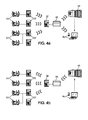
- a proximal automaton 32 may be associated with several ventilation devices 14 or with several blowers 64, for example a proximal automaton 32 may be associated with four blowers 64, or ten blowers 64. The number of blowers 64 to which the proximal automaton 32 is connected will determine the type of proximal automaton 32 used. However, possibly a proximal automaton 32 may be associated with a single ventilation device 14, and several sets comprising a ventilation device 14 and a proximal automaton 32 may be provided and be controlled via a single server 48 as shown on the figure 5 .
- a single distal automaton 38 may be associated with several proximal automata 32 and a single server 48, as shown in FIG. figure 5 .
- the data is then all grouped and saved in one place.
- the control data 28 may be the same for all the ventilation devices 14.
- the control data 28 may be different depending on the ventilation device 14.
- the parameter measured on the devices ventilation 14 giving rise to the control data 24 may be different according to the ventilation devices or be the same.
- a processor 66 may further be provided for executing a computer program product implementing steps A, B, C, D, E and / or F of the remote control method via the internet network of the building ventilation system 55. , and / or perform steps A ', B', C 'and / or D' of the remote control method via the Internet network of the ventilation system 55 of building 10.
- the ventilation system allows a real-time storage of plant monitoring information. The information found is likely to be consulted in real time by the project owner of the building via an internet interface.
- a diagnosis of a possible failure can be made by a diagnostic tool 62 and an alert can be sent to the maintenance operator for example.
- the ventilation system 55 also provides a diagnosis of the quality of the ventilation device 14 in real time and over a given period, for example by comparing the evolution of certain parameters or local variables with typical curves of evolution given .
- the ventilation system 55 makes it possible to monitor the maintenance operations, to display several operating parameters and thus to monitor the maintenance operation. For example, any maintenance operation performed will be reported and recorded in the ventilation system 55.
- the ventilation system 55 allows the maintenance technician to be charged through an on-site human machine interface and / or an Internet terminal and / or a mobile phone.
- the breakdowns of the ventilation device 14 are reduced and the response times also.
- the ventilation system 55 makes it possible to prioritize the maintenance operations.
- the ventilation system 55 also makes it possible to develop the maintenance plans on the basis of precise in situ analyzes of the ventilation devices 14 without moving a maintenance team.
- the system makes it possible to centrally obtain control data in connection with the operation of ventilation devices, and / or to centrally transmit control data in connection with the operation of the control devices.
- ventilation For example, an addressing system can be implemented by which each communicating object of the network is identified by a unique identifier.
- the relationship between the control and / or control data with each ventilation device is via the unique identifier.
- the control data in relation to the operation of the ventilation device includes both the information itself and the unique identifier of the ventilation device.
- the control data in relation to the operation of the ventilation device includes both the information itself and the unique identifier of the ventilation device.
- the server 48 (or other connected component of the network) can store a map of correspondence between the unique identifier of each device and the geographical position thereof. Thus, if the server 48 receives information relating to a given ventilation device, via a given proximal automaton and a distal automaton, the mapping makes it possible to identify the geographical location of the ventilation device in question. for intervention or maintenance for example.
- the communicating objects of the system may for example be assigned a unique identifier sequentially.
- each ventilation device is assigned respectively an identifier of 1 to 1, each proximal automaton an identifier of l + 1 to m, each distal automaton an identifier of m + 1 to n.
- the server 48 receives information relating to the ventilation device k, where k is between 1 and 1, via a given proximal automaton and a distal automaton, the mapping makes it possible to identify the geographical location of the device. ventilation device k for intervention or maintenance for example.
- each proximal and / or distal automaton can store the information relating to the ventilation devices it serves, and decide whether to transmit the information downstream only if it can reach the ventilation device k by this means.
- the distal automaton may not know all the ventilation devices it serves. It will first send a request to the proximal PLCs to which it is connected to ask them if one of them knows the ventilation device in question. It will transmit the data only to the proximal automaton informing it to be able to deliver it to the ventilation device k.
- the server 48 may issue a command to all the ventilators served by a given proximal automaton. It is sufficient that the control data is associated with the unique identifier of a given proximal automaton, and the latter, upon receipt of the data, will transmit to all the devices it serves. This description can also be applied to distal automata.
- each ventilation device comprises a unique identification in the XYZ format, where Z denotes the unique identifier of the distal automata (for example from 1 to n1), Y denotes the unique identifier of the proximal automata (for example from 1 to n2, n2 varying from one distal automaton to another) for each distal automaton, and X denotes the unique identifier of each ventilation device (for example from 1 to n3, n3 varying from one proximal automaton to another ) for each proximal automaton.
- the server 48 receives a control data in relation to the ventilation device k1.k2.k3 for the k1-th ventilation device served by the k2-th proximal automaton served by the k3-th distal automaton.
- the ventilation device can already know the values of k1, k2 and k3 concerning it, and generates the control data including the complete address.
- the address is generated cumulatively during the transmission of the data from the ventilation device to the server 48.
- the ventilation device transmits to the proximal automaton a datum associated with the identifier k1.
- the proximal automaton concatenates the value k2, and transmits to the distal automaton a data associated with the address k1.k2, and so on.
- the transmission of control data to a ventilation device can be done by limiting the communications, because the address carries the information as to the sequence of communicating objects by which to pass to reach the device concerned by the order.
- a particular code for example 0, may be used in the address to denote all objects communicating downstream of a given communicating object.
- the hierarchical embodiment just described is just one example. For example, it could have 4 levels or more, and not three as described above, depending on the complexity and structure of the systems to be addressed. As a variant, it could have only two levels, especially in the case where each proximal automaton corresponds to a single ventilation device.
Abstract
Module de système de ventilation (12) de bâtiment (10) pour contrôle et/ou commande à distance via le réseau Internet comprenant : o au moins un dispositif de ventilation (14) apte et destiné à être placé vers la sortie sommitale d'un conduit d'extraction d'air (18) du bâtiment (10), auquel est associé fonctionnellement un moyen avec sortie ou émission (22) d'une donnée de contrôle en relation avec le fonctionnement du dispositif de ventilation (14), et provenant du dispositif de ventilation (14) lui-même, ou d'un moyen de détection (30) associé au dispositif de ventilation (14), ou de l'environnement du dispositif de ventilation (14), et/ou un moyen avec entrée ou réception (26) d'une donnée de commande en relation avec le fonctionnement du dispositif de ventilation (14), et allant au dispositif de ventilation (14), le moyen avec sortie ou émission et/ou le moyen avec entrée ou réception étant proximal, o un automate proximal (32), programmé et pourvu d'une mémoire, associé au moyen avec sortie ou émission (22) et/ou au moyen avec entrée ou réception (26), ledit automate proximal (32) étant avec moyen de sortie ou d'émission (34) de donnée et/ou moyen d'entrée ou de réception de donnée (36), o un automate distal (38), programmé et pourvu d'une mémoire, avec moyen de sortie ou d'émission (42) de donnée et/ou moyen d'entrée ou de réception (44) de donnée, o un moyen de communication à distance de données, proximal (40), entre l'automate proximal (32) et l'automate distal (38) et/ou entre l'automate distal (38) et l'automate proximal (32), tel qu'une donnée pour le contrôle du fonctionnement du dispositif de ventilation (14) et/ ou une donnée pour la commande du fonctionnement du dispositif de ventilation (14) peut être communiquée à partir du et/ou au dispositif de ventilation (14) via l'automate proximal (32) et l'automate distal (38).Building ventilation system module (12) for control and / or remote control via the Internet network comprising: at least one ventilation device (14) adapted and intended to be placed towards the top outlet of an air extraction duct (18) of the building (10), to which a means with exit or emission ( 22) of a control data relating to the operation of the ventilation device (14), and coming from the ventilation device (14) itself, or a detection means (30) associated with the ventilation device ( 14), or the environment of the ventilation device (14), and / or means with input or reception (26) of a control data in relation to the operation of the ventilation device (14), and going to ventilation device (14), the means with output or emission and / or the means with input or reception being proximal, a proximal automaton (32), programmed and provided with a memory, associated with the means with output or emission (22) and / or the means with input or reception (26), said proximal automaton (32) being with output means or transmitting (34) data and / or data entry or reception means (36), a distal automaton (38), programmed and provided with a memory, with data output or transmission means (42) and / or data input or reception means (44), proximal data communication means (40) between the proximal automaton (32) and the distal automaton (38) and / or between the distal automaton (38) and the proximal automaton (32) , such that data for controlling the operation of the ventilation device (14) and / or data for controlling the operation of the ventilation device (14) can be communicated from and / or to the ventilation device (14) via the proximal automaton (32) and the distal automaton (38).
Description
L'invention concerne un module et un système de ventilation de bâtiment pouvant être piloté à distance via l'Internet.The invention relates to a module and a building ventilation system that can be controlled remotely via the Internet.
Le document
Le document
Le document
Le document
On connaît sur le marché des dispositifs de ventilation stato-mécanique, comme par exemple celui connu sous la marque DYN ASTATO®, destinés à être placés sur le toit du bâtiment concerné. Dans un tel dispositif, l'extracteur statique est équipé d'un dispositif mécanique, à savoir une turbine, qui assiste la ventilation naturelle quand les conditions du tirage naturel ne sont plus réunies ou quand les besoins le requièrent. Cette assistance mécanique est programmée en fonction de l'heure, moyennant une horloge, et de la température extérieure, moyennant une sonde de température, et/ou de la vitesse du vent, moyennant un anémomètre. On connaît également des dispositifs de ventilation naturelle et hybride basse pression assistée par induction d'air, comme par exemple celui connu sous la marque NAVAIR®.There are known on the market statomechanical ventilation devices, such as the one known under the trademark DYN ASTATO®, intended to be placed on the roof of the building concerned. In such a device, the static extractor is equipped with a mechanical device, namely a turbine, which assists natural ventilation when natural draft conditions are no longer met or when needs require it. This mechanical assistance is programmed according to the time, by means of a clock, and the outside temperature, by means of a temperature probe, and / or the speed of the wind, by means of an anemometer. Also known natural ventilation devices and hybrid low pressure assisted by induction of air, such as that known under the brand NAVAIR®.
De tels dispositifs de ventilation sont typiquement destinés à l'habitat collectif, un bâtiment donné comportant un ou plusieurs dispositifs de ventilation stato-mécanique avec ou sans induction d'air qui ventilent chacun un ou plusieurs conduits collectifs d'extraction d'air. Le plus souvent, une société assure la maintenance de ces dispositifs de ventilation, ce qui comprend la surveillance du bon fonctionnement, l'entretien préventif de routine, le réglage en cas de besoin, et la réparation de dysfonctionnement, de panne ou de défectuosités. S'agissant de l'habitat collectif, une même société donnée assure la maintenance des dispositifs de ventilation de plusieurs bâtiments proches ou distants les uns des autres.Such ventilation devices are typically intended for collective housing, a given building comprising one or more statomechanical ventilation devices with or without air induction, each of which ventilates one or more collective exhaust ducts. Most often, a company provides maintenance of these ventilation devices, which includes monitoring of proper operation, routine preventive maintenance, adjustment when needed, and repair of malfunction, breakdown or malfunctions. With regard to collective housing, the same company ensures the maintenance of the ventilation devices of several buildings near or distant from each other.
Une telle maintenance pose de nombreux problèmes. Elle impose non seulement un déplacement sur chaque site où se trouve chaque bâtiment, mais aussi de grimper sur le toit du bâtiment. Elle impose un certain délai. Elle est plus curative que préventive. Elle est donc coûteuse et peu fiable, entraînant des nuisances pour les occupants des logements pouvant être sérieuses en cas de panne stoppant la ventilation du logement et l'arrêt du chauffage et de l'utilisation de l'eau chaude sanitaire.Such maintenance poses many problems. It imposes not only a displacement on each site where each building is located, but also to climb on the roof of the building. It imposes a certain delay. It is more curative than preventive. It is therefore expensive and unreliable, causing nuisance to the occupants of housing that can be serious in case of failure stopping the ventilation of the housing and stopping the heating and the use of domestic hot water.
On pourra mentionner l'existence de systèmes intégrés de climatisation/chauffage tels que décrits dans
L'invention a pour but de remédier à ces problèmes.The object of the invention is to remedy these problems.
Ci-après, un exposé de l'invention telle que caractérisée dans les revendications.Hereinafter, a description of the invention as characterized in the claims.
Selon un premier aspect, l'invention a pour objet un module de système de ventilation de bâtiment pour contrôle et/ou commande à distance via le réseau Internet :
- ■ comprenant :
- o au moins un dispositif de ventilation apte et destiné à être placé vers la sortie sommitale d'un conduit d'extraction d'air du bâtiment, auquel est associé fonctionnellement un moyen avec sortie ou émission d'une donnée de contrôle en relation avec le fonctionnement du dispositif de ventilation, et provenant du dispositif de ventilation lui-même, ou d'un moyen de détection associé au dispositif de ventilation, ou de l'environnement du dispositif de ventilation, et/ou un moyen avec entrée ou réception d'une donnée de commande en relation avec le fonctionnement du dispositif de ventilation, et allant au dispositif de ventilation, le moyen avec sortie ou émission et/ou le moyen avec entrée ou réception étant proximal,
- o un automate proximal, programmé et pourvu d'une mémoire, associé au moyen avec sortie ou émission et/ou au moyen avec entrée ou réception, ledit automate proximal étant avec moyen de sortie ou d'émission de donnée et/ou moyen d'entrée ou de réception de donnée,
- o un automate distal, programmé et pourvu d'une mémoire, avec moyen de sortie ou d'émission de donnée et/ou moyen d'entrée ou de réception de donnée,
- o un moyen de communication à distance de données, proximal, entre l'automate proximal et l'automate distal et/ou entre l'automate distal et l'automate proximal,
- ■ tel que :
- o une donnée pour le contrôle du fonctionnement du dispositif de ventilation peut être communiquée du moyen avec sortie ou émission d'une donnée de contrôle associé au dispositif de ventilation via l'automate proximal puis l'automate distal, et la donnée pour le contrôle du fonctionnement du dispositif de ventilation est susceptible d'être reçue et communiquée via le réseau internet d'un serveur distant par un portail Internet accessible depuis un terminal internet de sorte à pouvoir contrôler à distance le fonctionnement du dispositif de ventilation depuis le terminal Internet et le portail Internet dudit serveur distant, et/ou
- o une donnée pour la commande du fonctionnement du dispositif de ventilation peut être communiquée au dispositif de ventilation, via l'automate distal puis l'automate proximal, et est susceptible d'être envoyée via le réseau internet d'un serveur distant à partir d'un terminal Internet et d'un portail Internet.
- ■ including:
- at least one ventilation device adapted and intended to be placed towards the top outlet of a building air extraction duct, to which is associated functionally means with output or emission of a control data in relation to the operation of the ventilation device, and coming from the ventilation device itself, or from a means of detection associated with the ventilation device, or from the environment of the ventilation device, and / or means with input or reception of a control data in relation to the operation of the ventilation device, and going to the ventilation device, the means with output or emission and / or the means with input or reception being proximal,
- o a proximal programmable, programmed and provided with a memory, associated with the means with output or emission and / or means with input or reception, said proximal automaton being with means of output or data transmission and / or means of input or receipt of data,
- a distal automaton, programmed and provided with a memory, with output or data transmission means and / or input or data reception means,
- a remote data communication means, proximal, between the proximal automaton and the distal automaton and / or between the distal automaton and the proximal automaton,
- ■ such as:
- a data item for the control of the operation of the ventilation device can be communicated from the means with output or emission of a control data item associated with the ventilation device via the proximal automaton then the distal automaton, and the data for the control of the ventilation device. operation of the ventilation device is likely to be received and communicated via the internet network of a remote server by an Internet portal accessible from an internet terminal so as to remotely control the operation of the ventilation device from the Internet terminal and the Internet portal of said remote server, and / or
- a data item for controlling the operation of the ventilation device can be communicated to the ventilation device, via the distal automaton then the proximal automaton, and can be sent via the internet network of a remote server from an Internet terminal and an Internet portal.
Par rapport à l'état de la technique antérieure, les avantages de l'invention sont l'accès à distance aux données de fonctionnement pour l'observation du fonctionnement du dispositif de ventilation. Ainsi, la surveillance du dispositif de ventilation ne se fait pas obligatoirement in situ. On assure une observation continue du dispositif de ventilation à distance sans intervention humaine sur le dispositif à surveiller. En outre, des éventuels dysfonctionnements sont détectés dès l'origine et des mesures préventives peuvent être entreprises avant que le dysfonctionnement ne s'aggrave. Ainsi, la présente invention permet un fonctionnement fiable du dispositif de ventilation tout en garantissant des coûts de fonctionnement et de maintenance peu élevés. En l'espèce, la présente invention permet aussi de communiquer à distance une commande au dispositif de ventilation.Compared to the state of the prior art, the advantages of the invention are the remote access to the operating data for the observation of the operation of the ventilation device. Thus, the monitoring of the ventilation device is not necessarily done in situ. It ensures a continuous observation of the remote ventilation device without human intervention on the device to monitor. In addition, any malfunctions are detected from the beginning and preventive measures can be taken before the malfunction gets worse. Thus, the present invention allows reliable operation of the ventilation device while ensuring low operating and maintenance costs. In the present case, the present invention also makes it possible to remotely communicate a command to the ventilation device.
Selon une réalisation, en cas de donnée de contrôle en relation avec le fonctionnement du dispositif de ventilation considérée comme significative d'une défectuosité majeure, un portail Internet et/ou un téléphone mobile et/ou un une boîte aux lettres électronique d'une personne chargée du contrôle du système de ventilation est agencé pour recevoir une alerte susceptible d'être envoyée via le réseau internet et/ou le réseau GPRS et/ou le réseau GSM. En d'autres termes, le module comporte des moyens de diagnostic pour déterminer une défectuosité majeure du fonctionnement du dispositif de ventilation et en alerter rapidement un opérateur. Ainsi, le module permet une réactivité dans la gestion des opérations de maintenance du dispositif de ventilation.According to one embodiment, in the case of control data in relation to the operation of the ventilation device considered significant of a major defect, an Internet portal and / or a mobile phone and / or a mailbox of a person The controller of the ventilation system is arranged to receive an alert that can be sent via the internet network and / or the GPRS network and / or the GSM network. In other words, the module comprises diagnostic means for determining a major malfunction of the ventilation device and quickly alerting an operator. Thus, the module allows responsiveness in the management of maintenance operations of the ventilation device.
Selon une réalisation, le dispositif de ventilation est un dispositif statique, dynamique, stato-dynamique, avec ou sans induction d'air. Ainsi, l'invention s'applique à tous les types de dispositifs de ventilation et peut notamment être mis en oeuvre avec des dispositifs de ventilation déjà existants dans des bâtiments.According to one embodiment, the ventilation device is a static, dynamic, stato-dynamic device, with or without induction of air. Thus, the invention applies to all types of ventilation devices and can in particular be implemented with existing ventilation devices in buildings.
Selon une réalisation, le moyen de communication à distance de données, proximal, est un réseau WI-FI ou GSM ou GPRS. Ainsi, le moyen de communication à distance assure un accès aux données du dispositif simple à mettre en oeuvre et sans limitation géographique.In one embodiment, the remote data communication means, proximal, is a WI-FI or GSM or GPRS network. Thus, the remote communication means provides access to the data of the simple device to implement and without geographical limitation.
Selon une réalisation, le système de ventilation comporte plusieurs dispositifs de ventilation, un automate proximal étant associé à un seul dispositif de ventilation ou à plusieurs dispositifs de ventilation, un automate distal, étant commun à plusieurs automates proximaux, le serveur pouvant être commun à l'ensemble du système de ventilation. Ainsi, il est possible d'obtenir des paramètres de contrôle et/ou de commande pour plusieurs dispositifs de ventilation par exemple et gérer un parc d'installations à distance.In one embodiment, the ventilation system comprises a plurality of ventilation devices, a proximal automaton being associated with a single ventilation device or with several ventilation devices, a distal automaton being common to several proximal automata, the server being able to be shared by the patient. whole ventilation system. Thus, it is possible to obtain control and / or control parameters for several ventilation devices, for example, and to manage a park of remote installations.
Selon un deuxième aspect, l'invention concerne un système de ventilation de bâtiment pour contrôle et/ou commande à distance via le réseau Internet comportant un module de système de ventilation de bâtiment pour contrôle et/ou commande à distance via le réseau tel que précédemment décrit et :
- o un serveur ayant un portail Internet accessible depuis un terminal Internet, avec moyen de sortie ou d'émission de donnée et/ou moyen d'entrée ou de réception de donnée,
- o un moyen de communication à distance de données, distal, entre l'automate distal et le serveur et/ou entre le serveur et l'automate distal,
- o une donnée pour le contrôle du fonctionnement du dispositif de ventilation peut être communiquée du moyen avec sortie ou émission d'une donnée de contrôle associé au dispositif de ventilation au serveur, via l'automate proximal puis l'automate distal, de sorte à pouvoir contrôler à distance le fonctionnement du dispositif de ventilation depuis le terminal Internet et le portail Internet, et/ou
- o une donnée pour la commande du fonctionnement du dispositif de ventilation peut être communiquée au dispositif de ventilation à partir du terminal Internet et du portail Internet, via le serveur, l'automate distal puis l'automate proximal.
- a server having an Internet portal accessible from an Internet terminal, with means of output or data transmission and / or means of input or reception of data,
- a remote data communication means, distal, between the distal PLC and the server and / or between the server and the distal PLC,
- a data item for the control of the operation of the ventilation device can be communicated from the means with output or emission of a control data item associated with the ventilation device to the server, via the proximal automaton then the distal automaton, so that it is possible to remotely control the operation of the ventilation device from the Internet terminal and the Internet portal, and / or
- o data for the control of the operation of the ventilation device can be communicated to the ventilation device from the Internet terminal and the Internet portal, via the server, the distal PLC and the proximal PLC.
On assure une observation continue du dispositif de ventilation à distance sans intervention humaine sur le dispositif à surveiller, et des éventuels dysfonctionnements sont détectés dès l'origine et des mesures préventives peuvent être entreprises avant que le dysfonctionnement ne s'aggrave.It ensures continuous observation of the remote ventilation device without human intervention on the device to monitor, and any malfunctions are detected from the outset and preventive measures can be taken before the malfunction is aggravated.
Selon une réalisation, le moyen de communication à distance de données, distal, est un réseau WI-FI ou GSM ou GPRS. Ainsi, le moyen de communication à distance assure un accès aux données du dispositif simple à mettre en oeuvre et sans limitation géographique.In one embodiment, the distal remote data communication means is a WI-FI or GSM or GPRS network. Thus, the remote communication means provides access to the data of the simple device to implement and without geographical limitation.
Selon un troisième aspect, l'invention concerne un procédé de contrôle à distance via le réseau Internet d'un système de ventilation de bâtiment tel que précédemment décrit qui comprend au moins les étapes :
- prévoir un dispositif de ventilation, auquel est associé fonctionnellement un moyen avec sortie ou émission d'une donnée de contrôle en relation avec le fonctionnement du dispositif de ventilation, et provenant du dispositif de ventilation lui-même, ou d'un moyen de détection associé au dispositif de ventilation, ou de l'environnement du dispositif de ventilation,
- mesurer, détecter et/ou collecter une donnée de contrôle en relation avec le fonctionnement du dispositif de ventilation,
- transmettre la donnée de contrôle en relation avec le fonctionnement du dispositif de ventilation du moyen avec sortie ou émission d'une donnée de contrôle du dispositif de ventilation à un moyen d'entrée ou de réception de donnée d'un automate proximal,
- transmettre la donnée de contrôle en relation avec le fonctionnement du dispositif de ventilation d'un moyen de sortie ou d'émission de donnée de l'automate proximal à un moyen d'entrée ou de réception de donnée d'un automate distal via un moyen de communication à distance de données, proximal,
- transmettre la donnée de contrôle en relation avec le fonctionnement du dispositif de ventilation d'un moyen de sortie ou d'émission de donnée de l'automate distal à un serveur via un moyen de communication à distance de données, distal,
- transmettre la donnée de contrôle en relation avec le fonctionnement du dispositif de ventilation du serveur à un portail Internet et/ ou sur un téléphone mobile intelligent.
- provide a ventilation device, to which is associated functionally means with output or emission of a control data in relation to the operation of the ventilation device, and from the ventilation device itself, or an associated detection means the ventilation device, or the environment of the ventilation device,
- measure, detect and / or collect control data in relation to the operation of the ventilation device,
- transmitting the control data in relation to the operation of the ventilation device of the means with output or emission of a control data of the ventilation device to a data input or reception means of a proximal automaton,
- transmitting the control data in relation to the operation of the ventilation device of an output or data transmission means of the proximal automaton to a data input or reception means of a distal automaton via means remote data communication, proximal,
- transmitting the control data in relation to the operation of the ventilation device of an output or data transmission means of the distal PLC to a server via a remote data communication means, distal,
- transmit the control data in relation to the operation of the server ventilation device to an Internet portal and / or a smart mobile phone.
Grâce à ces dispositions, il est possible d'avoir en temps réel une information sur l'état de fonctionnement du dispositif de ventilation et débuter si nécessaire une opération de maintenance.Thanks to these provisions, it is possible to have real-time information on the operating state of the ventilation device and start if necessary a maintenance operation.
Le procédé de contrôle à distance peut comprendre en outre une étape de diagnostic d'un état de fonctionnement du dispositif de ventilation à partir de la donnée de contrôle en relation avec le fonctionnement du dispositif de ventilation. Ainsi un système « intelligent » peut permettre par exemple de déterminer l'état de fonctionnement du dispositif de ventilation, diagnostiquer un dysfonctionnement et éventuellement de préconiser une action pour lutter contre ce dysfonctionnement.The remote control method may further comprise a step of diagnosing an operating state of the ventilation device from the control data in relation to the operation of the ventilation device. Thus an "intelligent" system can allow for example to determine the operating state of the ventilation device, diagnose a malfunction and possibly to recommend an action to combat this malfunction.
Le procédé de contrôle à distance peut comprendre en outre une étape d'enregistrement de la donnée de contrôle.The remote control method may further include a step of recording the control data.
Selon un quatrième aspect, l'invention concerne un procédé de commande à distance via le réseau Internet d'un système de ventilation de bâtiment tel que précédemment décrit qui comprend au moins les étapes :
- prévoir un dispositif de ventilation apte et destiné à être placé vers la partie sommitale d'un conduit d'extraction d'air, auquel est associé fonctionnellement un moyen avec entrée ou réception d'une donnée de commande en relation avec le fonctionnement du dispositif de ventilation,
- prévoir un portail Internet et un serveur,
- transmettre une donnée de la commande du serveur à un moyen d'entrée ou de réception de donnée d'un automate distal via un moyen de communication à distance de données, distal,
- transmettre la donnée de commande d'un moyen de sortie ou d'émission de donnée de l'automate distal vers un moyen d'entrée ou de réception de donnée d'un automate proximal via un moyen de communication à distance de données, proximal,
- transmettre la donnée de commande d'un moyen de sortie ou d'émission de donnée de l'automate proximal vers un moyen d'entrée ou de réception de données du dispositif de ventilation.
- provide a ventilation device adapted and intended to be placed towards the upper part of an air extraction duct, to which is associated functionally means with input or reception of a control data in relation to the operation of the device of ventilation,
- provide an Internet portal and a server,
- transmitting data from the server control to a data input or data receiving means of a distal PLC via distal data communication means,
- transmitting the control data of an output or data transmission means of the distal state machine to a data input or reception means of a proximal state machine via a remote data communication means, proximal,
- transmitting the control data of an output or data transmission means of the proximal automaton to a data input or reception means of the ventilation device.
Grâce à ces dispositions, il est possible de commander à distance les paramètres de fonctionnement du dispositif de ventilation.Thanks to these arrangements, it is possible to remotely control the operating parameters of the ventilation device.
Le procédé peut en outre comprendre une étape de réglage et/ou de réparation de dysfonctionnement, de panne ou de défectuosité du dispositif de ventilation. Ainsi, aucun déplacement sur place n'est nécessaire pour effectuer des opérations de maintenance préventive ou curative.The method may further include a step of adjusting and / or repairing malfunction, failure, or malfunction of the venting device. Thus, no displacement on site is necessary to carry out preventive or curative maintenance operations.
Selon un cinquième aspect, l'invention concerne un produit programme informatique comprenant des instructions pour mettre en oeuvre l'un et/ou l'autre des procédés décrits ci-dessus lors d'une exécution de ce programme par un processeur.According to a fifth aspect, the invention relates to a computer program product comprising instructions for implementing one and / or the other of the methods described above when executing this program by a processor.
On décrit maintenant brièvement les figures des dessins.
- La
figure 1 est une vue schématique des différents composants du système de ventilation avec un module de système de ventilation selon un mode de réalisation de l'invention et un serveur sur un bâtiment. - La
figure 2 est une vue schématique des différents éléments du système de ventilation avec un module de système de ventilation et un serveur de lafigure 1 , et de leurs interactions. - La
figure 3a est un diagramme représentant les différentes étapes du procédé de contrôle à distance via le réseau internet d'un système de ventilation selon l'invention. - La
figure 3b est un diagramme représentant les différentes étapes du procédé de commande à distance via le réseau internet d'un système de ventilation selon l'invention. - La
figure 4a est une vue schématique d'un système de ventilation avec un module de système de ventilation et un serveur tels que représentés sur lafigure 2 réalisant les étapes du procédé de contrôle à distance représentées par le diagramme de lafigure 3a . - La
figure 4b est une vue schématique d'un système de ventilation avec un module de système de ventilation et un serveur tels que représentés sur lafigure 2 réalisant les étapes du procédé de commande à distance représentées par le diagramme de lafigure 3b . - La
figure 5 est une vue schématique d'un système de ventilation avec un module de système de ventilation selon un mode de réalisation de l'invention selon une variante de réalisation de l'invention et un serveur.
- The
figure 1 is a schematic view of the various components of the ventilation system with a ventilation system module according to an embodiment of the invention and a server on a building. - The
figure 2 is a schematic view of the various elements of the ventilation system with a ventilation system module and a server of thefigure 1 , and their interactions. - The
figure 3a is a diagram representing the various steps of the remote control method via the Internet network of a ventilation system according to the invention. - The
figure 3b is a diagram representing the various steps of the remote control method via the Internet network of a ventilation system according to the invention. - The
figure 4a is a schematic view of a ventilation system with a ventilation system module and a server as shown in FIG.figure 2 performing the steps of the remote control method represented by the diagram of thefigure 3a . - The
figure 4b is a schematic view of a ventilation system with a ventilation system module and a server as shown in FIG.figure 2 performing the steps of the remote control method represented by the diagram of thefigure 3b . - The
figure 5 is a schematic view of a ventilation system with a ventilation system module according to an embodiment of the invention according to an alternative embodiment of the invention and a server.
Ci-après un exposé détaillé de plusieurs modes de réalisation de l'invention assorti d'exemples et de référence aux dessins.Hereinafter a detailed discussion of several embodiments of the invention with examples and reference to the drawings.
En référence aux
Le dispositif de ventilation 14 est, dans une première variante un dispositif de ventilation statique. Par exemple, le dispositif de ventilation statique a pour seuls moteurs le tirage thermique (lié à la différence de température entre l'intérieur et l'extérieur du logement) et le vent (tirage éolien). Dans une deuxième variante de réalisation, le dispositif de ventilation est dynamique, à savoir mécanisée et qui maintient en permanence des conditions de tirage particulières. Dans une troisième variante de réalisation, le dispositif de ventilation est stato-dynamique, à savoir un dispositif mécanique vient assister un dispositif statique quand les conditions naturelles de tirage ne sont plus réunies. En outre, le dispositif de ventilation peut être prévu avec ou sans induction d'air.The
Toutefois, l'invention n'est pas limitée à la ventilation naturelle et hybride de bâtiments, elle peut être appliquée à tous types d'installations de ventilation. Par exemple, elle peut être appliquée à la ventilation haute, moyenne, basse ou très basse pression, ou encore à l'évacuation des produits de combustion en ventilation mécanique contrôlée.However, the invention is not limited to the natural and hybrid ventilation of buildings, it can be applied to all types of ventilation systems. For example, it can be applied to high, medium, low or very low pressure ventilation, or to the evacuation of combustion products in controlled mechanical ventilation.
Le dispositif de ventilation 14 est placé vers la sortie du conduit d'extraction d'air 18 du bâtiment 10. Tel qu'illustré sur la
Un moyen de sortie ou d'émission 22 d'une donnée de contrôle 24 et/ou un moyen d'entrée ou de réception 26 d'une donnée de commande 28 est (sont) associé(s) au dispositif de ventilation 14. En d'autre termes, un organe d'émission de la donnée de contrôle 24 et/ou un organe de réception de la donnée de commande 28 est associé fonctionnellement au dispositif de ventilation 14. Dans une variante de réalisation avec plusieurs dispositifs de ventilation 14, un ou plusieurs moyen(s) avec sortie ou émission 22 d'une donnée de contrôle 24 et/ou un ou plusieurs moyen(s) d'entrée ou de réception 26 d'une donnée de commande 28 est (sont) associé(s) aux dispositifs de ventilation 14.An output or transmission means 22 of a
Le moyen de sortie ou d'émission 22 du dispositif de ventilation 14 (ou plus précisément associé au dispositif de ventilation 14) d'une donnée de contrôle 24 est agencé au voisinage (ou en d'autres termes proche) du dispositif de ventilation 14. Plus précisément, le moyen de sortie ou d'émission 22 va permettre la communication d'une donnée de contrôle 24 en relation directe avec le fonctionnement du dispositif de ventilation 14 vers l'extérieur du dispositif de ventilation 14. Le moyen de sortie ou d'émission 22 peut être filaire et par conséquent être relié au dispositif de ventilation par un câble. Dans une variante, le moyen de sortie ou d'émission 22 est un émetteur sans fil et peut par exemple être relié au dispositif de ventilation 14 par télémétrie, ou toute autre technique d'émission à distance.The output or emission means 22 of the ventilation device 14 (or more precisely associated with the ventilation device 14) of a
La donnée de contrôle 24 peut provenir du dispositif de ventilation 14 directement. En variante, un moyen de détection 30 ou encore un organe de détection, tel qu'un capteur peut être prévu tel qu'illustré sur la
Par exemple, la donnée de contrôle 24 est une donnée représentative de l'état de fonctionnement du dispositif de ventilation 14 et peut être la consommation électrique du dispositif de ventilation 14 dans le cas d'un dispositif dynamique, et/ou le débit de tirage du dispositif de ventilation 14, et/ou la vitesse des moteurs, et/ou une concentration de certains gaz. La donnée de contrôle 24 du dispositif de ventilation 14, ou au moins en relation avec le fonctionnement du dispositif de ventilation 14 peut par exemple prendre des valeurs significatives d'un dysfonctionnement majeur ou d'une défectuosité majeure du dispositif de ventilation 14.For example, the
En variante complémentaire ou alternative, la donnée de contrôle 24 peut surveiller le comportement en fonctionnement normal du dispositif de ventilation 14 et par exemple donner une indication sur une optimisation des paramètres de fonctionnement du dispositif de ventilation 14. La donnée de contrôle 24 peut également servir à déterminer le comportement du dispositif de ventilation 14 afin d'en analyser ses réponses. Autrement dit, la donnée de contrôle 24 sera à déterminer en fonction des besoins liés à l'installation sur le bâtiment 10 et à l'environnement du bâtiment 10.As a complementary or alternative variant, the
En outre, la donnée de contrôle 24 peut être composée d'une pluralité de « sous-données de contrôles ». En l'espèce plusieurs données de contrôle 24 peuvent être détectés ou émises de façon simultanée ou au contraire de façon consécutive ou séquentielle.In addition, the
En complément ou en remplacement du moyen avec sortie ou émission 22 du dispositif de ventilation 14, le moyen avec entrée ou réception 26 d'une donnée de commande 28 est associé au dispositif de ventilation 14. Le moyen avec entrée ou réception 26 est agencé au voisinage du dispositif de ventilation 14. En d'autres termes, le moyen avec entrée ou réception 26 est agencé proche du dispositif de ventilation 14.In addition to or in replacement of the means with output or
Le moyen avec entrée ou réception 26 du dispositif de ventilation 14 va permettre au dispositif de ventilation 14 de recevoir une donnée de commande 28 depuis l'extérieur du dispositif de ventilation 14. Le moyen avec entrée ou réception 26 est associé au dispositif de ventilation 14 de façon filaire, ou encore sans fil. Par exemple, le moyen avec entrée ou réception 26 est un récepteur et est associé au dispositif de ventilation 14 par télémétrie.The means with input or
Le moyen avec entrée ou réception 26 est destiné à recevoir une donnée de commande 28. La donnée de commande 28 apporte une instruction au dispositif de ventilation 14 ou au voisinage du dispositif de ventilation 14 et peut être exécutée comme précisé ci-après. En outre, plusieurs données de commande 28 peuvent être reçues.The means with input or
Le module de système de ventilation 12 comporte également un automate proximal 32. L'automate proximal 32 est avantageusement agencé ou situé proche ou au voisinage du dispositif de ventilation 14. Par exemple, dans le cas d'un module de système de ventilation 12 de bâtiment 10, l'automate proximal 32 est in situ, à savoir dans ou à proximité du bâtiment 10. L'automate proximal 32 est programmé et pourvu d'une mémoire. L'automate proximal 32 est associé au moyen de sortie ou d'émission 22 d'une donnée de contrôle 24 et/ou au moyen d'entrée ou de réception 26 d'une donnée de commande 28. L'automate proximal 32 mémorise la donnée de contrôle 24 et/ou la donnée de commande 28 à envoyer par exemple.The
L'automate proximal 32 est associé au moyen de sortie ou d'émission 22 d'une donnée de contrôle 24 et/ou au moyen d'entrée ou de réception 26 d'une donnée de commande 28 par exemple de façon filaire, ou encore de façon sans fil.The
L'automate proximal 32 comporte un moyen de sortie ou d'émission de données 34 et/ou un moyen d'entrée ou de réception de données 36. Le moyen de sortie ou d'émission de données 34 est destiné à envoyer la donnée de contrôle 24 et/ou de commande 28, tandis que le moyen avec entrée ou réception de données 36 est destiné à recevoir une donnée de commande 28 et/ou de contrôle 24. La donnée de contrôle 24 et/ou la donnée de commande 28 peut (peuvent) être sensiblement la (les) même(s) que celle(s) émise et/ou reçue par le moyen de sortie ou d'émission 22 du dispositif de ventilation 14 et/ou le moyen d'entrée ou de réception 26 du dispositif de ventilation 14 ou être une donnée post-traitée et/ou prétraitée.The
Le moyen de sortie ou d'émission de données 34 de l'automate proximal 32 est par exemple un émetteur adapté pour transmette la donnée de commande 28 au dispositif de ventilation 14, ou encore hors de l'automate proximal 32. La transmission peut se faire à distance, par exemple le moyen de sortie ou d'émission de données 34 peut émettre des signaux par ondes électromagnétiques, ou encore par infrarouge. Dans une variante de réalisation, la transmission est de type filaire.The output or data transmission means 34 of the
L'automate proximal 32 comporte, en complément ou en remplacement de son moyen de sortie ou d'émission de données 34, le moyen d'entrée ou de réception de données 36. Le moyen d'entrée ou de réception de données 36 est par exemple un récepteur adapté pour recevoir la donnée de contrôle 24 du dispositif de ventilation 14 envoyée par le moyen de sortie ou d'émission 22 du dispositif de ventilation 14. La réception de la donnée de contrôle 24 est par exemple sans fil. Dans une variante de réalisation, la réception de la donnée de contrôle 24 est réalisée de façon filaire, par exemple par l'intermédiaire d'un câble.The
Le module de système de ventilation 12 comporte un automate distal 38. Le module de système de ventilation 12 comporte un moyen de communication à distance de données, proximal, 40 entre l'automate distal 38 et l'automate proximal 32.The
Le moyen de communication à distance de données, proximal, 40 (encore appelé ci-après moyen de communication proximal 40) est par exemple un réseau WI-FI ou un réseau GSM ou un réseau GPRS. Le moyen de communication proximal 40 va permettre d'assurer la connexion de données entre l'automate distal 38 et l'automate proximal 32 et/ou entre l'automate proximal 32 et l'automate distal 38. Ainsi, une donnée de contrôle 24 du dispositif de ventilation 14 peut être envoyée par l'automate proximal 32 dans lequel elle a été stockée vers l'automate distal 38 via le moyen de communication proximal 40, par exemple via le réseau WI-FI ou le réseau GSM ou le réseau GPRS.The remote proximal data communication means 40 (hereinafter also referred to as proximal communication means 40) is for example a WI-FI network or a GSM network or a GPRS network. The proximal communication means 40 will make it possible to ensure the data connection between the
L'automate distal 38 est situé à distance du dispositif de ventilation 14. Dans le cas d'un système de bâtiments, l'automate distal 38 est par exemple ex situ, à savoir hors du bâtiment 10, et par exemple éloigné du bâtiment 10. L'automate distal 38 est par exemple situé dans une plateforme logistique de l'organisme de maintenance du dispositif de ventilation. L'automate distal 38 est programmé. L'automate distal 38 a une mémoire. L'automate distal 38 mémorise la donnée de contrôle 24 et/ou de commande 28 à envoyer ou à transmettre par exemple. L'automate distal 38 est adapté pour recevoir des données via le moyen de communication proximal 40. Par l'intermédiaire le moyen de communication proximal 40, les données de commande 24 et/ou de contrôle 28 peuvent être envoyées à intervalles réguliers et mémorisée dans l'automate distal et/ou proximal les recevant.The
L'automate distal 38 comporte en outre un moyen de sortie ou d'émission de données 42 et/ou un moyen d'entrée ou de réception de données 44.The
Le moyen de sortie ou d'émission de données 42 de l'automate distal 38 peut émettre sans fil, avec par exemple des signaux par ondes électromagnétiques, ou encore par infrarouge. Dans une variante de réalisation, le moyen de sortie ou d'émission de données 42 de l'automate distal 38 est filaire.The output or data transmission means 42 of the
En complément ou en remplacement du moyen de sortie ou d'émission de données 42, le moyen d'entrée ou de réception de données 44 est associé à l'automate distal 38. Le moyen d'entrée ou de réception de données 44 de l'automate distal 38 est par exemple un récepteur adapté pour recevoir la donnée de commande 28 et/ou de contrôle 24 à distance. Dans une variante de réalisation, le moyen d'entrée ou de réception de données 44 reçoit la donnée de commande 28 et/ou de contrôle à distance 24 par une transmission filaire.In addition to or in replacement of the output or data transmission means 42, the data input or reception means 44 is associated with the
Ainsi, le module de système de ventilation 12 comporte le dispositif de ventilation 14, l'automate proximal 32, l'automate distal 38, le moyen de communication à distance, proximal, 40 et éventuellement le moyen de détection 30.Thus, the
Dans une variante de réalisation, l'automate distal 38 est équipé d'un modem 46 (cf.
L'envoi des données entre le serveur 48 et l'automate distal 38 et/ou entre l'automate distal 38 et le serveur 48 est réalisé à distance via un moyen de communication à distance de données, distal 50 (encore appelé moyen de communication distal 50). Le moyen de communication distal 50 est par exemple un réseau GSM ou WI-FI ou GPRS.The sending of data between the
Le serveur 48 est un élément du système de ventilation 12. Le serveur 48 est adapté pour mémoriser une pluralité de données de commande 28 et/ou de contrôle 24. Les données, notamment les données de contrôle 24 sont ensuite consultables par l'intermédiaire d'un portail internet 52 et permette de suivre le comportement du dispositif de ventilation 12. En d'autres termes, le serveur 48 comporte un portail internet 52 accessible depuis un terminal internet 54. En outre, le serveur 48 comporte un moyen de sortie ou d'émission de donnée 56 et/ou un moyen d'entrée ou de réception de données 58.The
L'ensemble comprenant le serveur 48 avec portail Internet 52 consultable depuis un terminal Internet 54, le moyen de communication à distance de données, distal 50 et le module de système de ventilation 12 forme le système de ventilation 55.The assembly comprising the
En variante, le modem 46 associé à l'automate distal 38, ou un moyen d'émission 42 de l'automate distal 38 envoi une donnée de contrôle 24 à un organe de communication intelligent personnel 60, tel qu'un ordinateur portable ou un téléphone portable d'un opérateur, par exemple d'un opérateur de maintenance en charge de surveiller le comportement du dispositif de ventilation 14, ou en charge de surveiller une anomalie de fonctionnement du dispositif de ventilation 14.Alternatively, the
Les
Tout d'abord, à l'étape A, le détecteur 30 ou encore des capteurs mesurent une ou plusieurs données de fonctionnement (encore appelées donnée(s) de contrôle 24) du dispositif de ventilation 14. Il peut être prévu de mesurer la ou les données de contrôle 24 de façon continue ou d'effectuer la mesure à intervalle de temps régulier prédéterminer, ou encore sur commande d'un opérateur.First, in step A, the
Dans une autre variante de réalisation on peut prévoir un capteur mesurant en continu mais adapté pour déclencher la transmission de la donnée de contrôle 24 une fois qu'un seuil maximal ou minimal préalablement défini est atteint.In another variant embodiment, it is possible to provide a sensor measuring continuously but adapted to trigger the transmission of the
A l'étape B, la ou les donnée(s) de contrôle 24 est (sont) transmise(s) à un automate proximal 32 via le moyen de sortie ou d'émission 22 du dispositif de ventilation 14 (plus précisément, via le moyen de sortie ou d'émission 22 associé au dispositif de ventilation 14). En l'espèce, la donnée de contrôle 24 est reçue par le moyen d'entrée ou de réception de donnée 36 de l'automate proximal 32. L'automate proximal 32 enregistre la donnée de contrôle 24. Eventuellement, l'automate proximal est adapté pour modifier et/ou traiter la donnée de contrôle 24.In step B, the control data (s) 24 is (are) transmitted (s) to a
La donnée de contrôle 24 est transmise de l'automate proximal 32 à l'automate distal 38 via le moyen de communication proximal 40, par exemple par réseau WI-FI ou GSM ou GPRS (étape C). La donnée de contrôle 24 est par exemple, transmise d'un moyen d'émission de données 34 de l'automate proximal 32 à un moyen de réception de données 44 de l'automate distal 38.The
L'automate distal 38 transmet la donnée de contrôle 24 au serveur 48 par le moyen de communication distal 50, par exemple par réseau WI-FI ou GSM ou GPRS (étape D). Alternativement ou de façon complémentaire, la donnée de contrôle 24 est transmise par exemple par l'intermédiaire du modem 46 associé à l'automate distal 38 à un organe de communication intelligent personnel 60 d'un opérateur de maintenance, par exemple un courriel et/ou un message texte est envoyé sur l'ordinateur portable ou sur le téléphone portable d'un opérateur (étape E).The
Les données de contrôle 24 sont au fur et à mesure et en temps réel stockées et mises en ligne ou mises à disposition du personnel compétent via le serveur 48 comprenant le portail internet 52 accessible depuis le terminal internet 54 (étape F).The
Le procédé de contrôle à distance peut également comporter une étape de diagnostic par un outil de diagnostic 62 d'un état de fonctionnement incorrect du dispositif de ventilation 14 (étape G). Eventuellement une étape de transmission du diagnostic à un opérateur peut avoir lieue (Etape H).The remote control method may also include a diagnostic step by a
Les
Tout d'abord, à l'étape A' des paramètres de régulation du dispositif de ventilation 14 sont modifiés. Par exemple, un opérateur entre de nouveaux paramètres ou encore, un logiciel vient modifier de façon autonome les paramètres de régulation du dispositif de ventilation 14. La modification des paramètres peuvent avoir plusieurs origines, par exemple elle peut être due et dépendante de la donnée de contrôle 24 préalablement mesurée, ou encore elle peut être dépendante de paramètres extérieurs environnementaux tels que la force du vent ou encore la température. Les paramètres de régulation du dispositif de ventilation 14 sont modifiés via un terminal internet 54 et mémorisé par le serveur 48. Les paramètres de régulation du dispositif de ventilation 14 modifiés génèrent une ou plusieurs donnée(s) de commande 28.First, in step A ', regulating parameters of the
A l'étape B', l'automate distal 38 reçoit la donnée de commande 28. L'automate distal 38 enregistre la donnée de commande 28. L'automate distal 38 reçoit la donnée de commande 28 via le moyen de communication distal 50.In step B ', the
A l'étape C', l'automate proximal 32 reçoit la donnée de commande 28 de l'automate proximal 38 par le moyen de communication proximal 40. L'automate proximal 32 enregistre la donnée de commande 28.In step C ', the
L'automate proximal 32 envoie la donnée de commande 28 au dispositif de ventilation 14, ou à un organe adapté pour agir sur le dispositif de ventilation 14 ou sur les paramètres du dispositif de ventilation 14 et pour commander le changement d'état désiré du dispositif de ventilation 14 (étape D'). Ainsi, par exemple l'automate proximal 38 va commander la régulation de la vitesse d'une soufflante 64 (cf.
On assure ainsi à distance une modification du fonctionnement du dispositif de ventilation 14 en modifiant à distance des paramètres de régulation du dispositif.In this way, a change in the operation of the
Les réceptions et émissions de la donnée de commande 28 par les différents éléments composant le système de ventilation 12 (le dispositif de ventilation 14, l'automate proximal 32, l'automate distal 38, le serveur 48) peuvent transiter par des moyens de réception ou entrée 26, 36, 44, 58 et/ou des moyens d'émission ou sortie 22, 34, 42, 56 associés à chaque éléments par exemple.The reception and transmission of the
Dans des variantes de réalisation, un automate proximal 32 peut être associé à plusieurs dispositifs de ventilation 14 ou encore à plusieurs soufflantes 64, par exemple un automate proximal 32 peut être associé à quatre soufflantes 64, ou encore dix soufflantes 64. Le nombre de soufflantes 64 auquel l'automate proximal 32 est relié déterminera le type d'automate proximal 32 utilisé. Toutefois, éventuellement un automate proximal 32 peut être associé à un seul dispositif de ventilation 14, et plusieurs ensembles comprenant un dispositif de ventilation 14 et un automate proximal 32 peuvent être prévus et être commandé par l'intermédiaire d'un seul et même serveur 48, comme illustré sur la
Un seul automate distal 38 peut être associé à plusieurs automates proximaux 32 et à un seul serveur 48, comme illustré sur la
La donnée de commande 28 peut être la même pour l'ensemble des dispositifs de ventilation 14. La donnée de commande 28 peut être différentes selon le dispositif de ventilations 14. Le paramètre mesuré sur les dispositifs de ventilation 14 donnant naissance aux données de contrôle 24 peut être différent selon les dispositifs de ventilation ou être le même.The
Un processeur 66 peut en outre être prévu pour exécuter un produit programme informatique mettant en oeuvre les étapes A, B, C, D, E et/ou F du procédé de contrôle à distance via le réseau internet du système de ventilation 55 de bâtiment 10, et/ou exécuter les étapes A', B', C' et/ou D' du procédé de commande à distance via le réseau internet du système de ventilation 55 de bâtiment 10.A
Ainsi, il sera possible de télé-surveiller des dispositifs de ventilation 14, ou encore des parcs comprenant une pluralité de dispositifs de ventilation 14. Le système de ventilation permet une mise en mémoire en temps réel d'informations de surveillance des installations. Les informations relevées sont susceptibles d'être consultées en temps réel par la maitrise d'ouvrage du bâtiment via une interface internet.Thus, it will be possible to remotely monitor
Un diagnostic d'une panne éventuelle peut être réalisé par un outil de diagnostic 62 et une alerte peut être envoyée à l'opérateur de maintenance par exemple. En outre, le système de ventilation 55 assure également un diagnostic de la qualité du dispositif de ventilation 14 en temps réel et sur une période donnée, par exemple en comparant l'évolution de certains paramètres ou variables locales avec des courbes type d'évolution données.A diagnosis of a possible failure can be made by a
Le système de ventilation 55 permet de suivre les opérations de maintenance, d'afficher plusieurs paramètres de fonctionnement et ainsi assure un suivi de l'opération de maintenance. Par exemple, tout opération de maintenance réalisée sera signalée et enregistrée dans le système de ventilation 55. En outre, le système de ventilation 55 permet un pointage du technicien de maintenance en charge par l'intermédiaire d'une interface homme machine sur site et/ou d'un terminal Internet et/ou d'un téléphone mobile.The
Les pannes du dispositif de ventilation 14 sont réduites et les délais d'intervention également.The breakdowns of the
En outre, le système de ventilation 55 permet de prioriser les opérations de maintenance. Le système de ventilation 55 permet également de développer les plans de maintenance sur la base d'analyses in situ précises des dispositifs de ventilation 14 sans déplacement d'une équipe de maintenance.In addition, the
Comme décrit ci-dessus, le système permet d'obtenir de manière centralisée des données de contrôle en relation avec le fonctionnement de dispositifs de ventilation, et/ou d'émettre de manière centralisée des données de commande en relation avec le fonctionnement de dispositifs de ventilation. On peut par exemple mettre en oeuvre un système d'adressage par lequel chaque objet communiquant du réseau est identifié par un identifiant unique. Ainsi, la relation entre la donnée de contrôle et/ou de commande avec chaque dispositif de ventilation se fait via l'identifiant unique. Ainsi, la donnée de contrôle en relation avec le fonctionnement du dispositif de ventilation comprend à la fois l'information elle-même et l'identifiant unique du dispositif de ventilation. La donnée de commande en relation avec le fonctionnement du dispositif de ventilation comprend à la fois l'information elle-même et l'identifiant unique du dispositif de ventilation.As described above, the system makes it possible to centrally obtain control data in connection with the operation of ventilation devices, and / or to centrally transmit control data in connection with the operation of the control devices. ventilation. For example, an addressing system can be implemented by which each communicating object of the network is identified by a unique identifier. Thus, the relationship between the control and / or control data with each ventilation device is via the unique identifier. Thus, the control data in relation to the operation of the ventilation device includes both the information itself and the unique identifier of the ventilation device. The control data in relation to the operation of the ventilation device includes both the information itself and the unique identifier of the ventilation device.
Le serveur 48 (ou un autre composant connecté du réseau) peut stocker une cartographie de correspondance entre l'identifiant unique de chaque appareil et la position géographique de celui-ci. Ainsi, si le serveur 48 reçoit une information relative à un dispositif de ventilation donné, par l'intermédiaire d'un automate proximal et d'un automate distal donnés, la cartographie permet d'identifier l'emplacement géographique du dispositif de ventilation en question en vue d'une intervention ou d'une maintenance par exemple.The server 48 (or other connected component of the network) can store a map of correspondence between the unique identifier of each device and the geographical position thereof. Thus, if the
Les objets communiquants du système peuvent par exemple se voir affecter un identifiant unique de manière séquentielle. Par exemple, chaque dispositif de ventilation se voit affecter respectivement un identifiant de 1 à l, chaque automate proximal un identifiant de l+1 à m, chaque automate distal un identifiant de m+1 à n. Si le serveur 48 reçoit une information relative au dispositif de ventilation k, k étant compris entre 1 et l, par l'intermédiaire d'un automate proximal et d'un automate distal donnés, la cartographie permet d'identifier l'emplacement géographique du dispositif de ventilation k en vue d'une intervention ou d'une maintenance par exemple.The communicating objects of the system may for example be assigned a unique identifier sequentially. For example, each ventilation device is assigned respectively an identifier of 1 to 1, each proximal automaton an identifier of l + 1 to m, each distal automaton an identifier of m + 1 to n. If the
En alternative, si le serveur 48 émet une commande en direction du dispositif de ventilation k, celle-ci est relayée jusqu'à ce dernier par l'intermédiaire des automates proximal et distal qui lui sont associés. Ainsi, chaque automate proximal et/ou distal peut stocker l'information relative aux dispositifs de ventilation qu'il dessert, et décider de transmettre ou non l'information en aval seulement si elle peut atteindre le dispositif de ventilation k par ce biais.Alternatively, if the
En particulier, l'automate distal peut ne pas connaître tous les dispositifs de ventilation qu'il dessert. Il enverra d'abord une requête aux automates proximaux auxquels il est connecté pour leur demander si l'un d'entre eux connait le dispositif de ventilation en question. Il ne transmettra la donnée qu'à l'automate proximal l'informant pouvoir la délivrer au dispositif de ventilation k.In particular, the distal automaton may not know all the ventilation devices it serves. It will first send a request to the proximal PLCs to which it is connected to ask them if one of them knows the ventilation device in question. It will transmit the data only to the proximal automaton informing it to be able to deliver it to the ventilation device k.
De manière pratique, le serveur 48 peut émettre une commande en direction de l'ensemble des dispositifs de ventilation desservis par un automate proximal donné. Il suffit que la donnée de commande soit associée à l'identifiant unique d'un automate proximal donné, et celui-ci, à réception de la donnée, transmettra à l'ensemble des dispositifs qu'il dessert. Cette description peut également s'appliquer aux automates distaux.Conveniently, the
En variante, on n'utilisera pas nécessairement un adressage séquentiel. On peut utiliser un adressage hiérarchique. Par exemple, chaque dispositif de ventilation comprend une identification unique sous le format X.Y.Z, où Z désigne l'identifiant unique des automates distaux (par exemple de 1 à n1), Y désigne l'identifiant unique des automates proximaux (par exemple de 1 à n2, n2 variant d'un automate distal à l'autre) pour chaque automate distal, et X désigne l'identifiant unique de chaque dispositif de ventilation (par exemple de 1 à n3, n3 variant d'un automate proximal à l'autre) pour chaque automate proximal. Une telle construction hiérarchique facilite l'intégration de nouveaux conduits d'extraction d'air, bâtiments ou ensemble de bâtiments dans le système, car il suffit d'incrémenter les bornes maximales n1, n2, n3.As a variant, a sequential addressing will not necessarily be used. Hierarchical addressing can be used. For example, each ventilation device comprises a unique identification in the XYZ format, where Z denotes the unique identifier of the distal automata (for example from 1 to n1), Y denotes the unique identifier of the proximal automata (for example from 1 to n2, n2 varying from one distal automaton to another) for each distal automaton, and X denotes the unique identifier of each ventilation device (for example from 1 to n3, n3 varying from one proximal automaton to another ) for each proximal automaton. Such a hierarchical construction facilitates the integration of new air extraction ducts, buildings or sets of buildings in the system, because it is sufficient to increment the maximum limits n1, n2, n3.
De cette manière, le serveur 48 reçoit une donnée de contrôle en relation avec le dispositif de ventilation k1.k2.k3 pour le k1-ème dispositif de ventilation desservi parle k2-ème automate proximal desservi par le k3-ème automate distal. Le dispositif de ventilation peut déjà connaitre les valeurs de k1, k2 et k3 le concernant, et génère la donnée de commande comportant l'adresse complète. En variante, l'adresse est générée de manière cumulative lors de la transmission de la donnée depuis le dispositif de ventilation vers le serveur 48. Ainsi, le dispositif de ventilation transmet à l'automate proximal une donnée associée à l'identifiant k1. Puis l'automate proximal y concatène la valeur k2, et transmet à l'automate distal une donnée associée à l'adresse k1.k2, et ainsi de suite.In this manner, the
Selon cette hiérarchie, l'émission de donnée de commande en direction d'un dispositif de ventilation peut se faire en limitant les communications, car l'adresse porte l'information quant à la séquence d'objets communiquants par qui passer pour atteindre le dispositif de ventilation concerné par la commande. Un code particulier, par exemple 0, peut être utilisé dans l'adresse pour désigner tous les objets communiquant en aval d'un objet communiquant donné.According to this hierarchy, the transmission of control data to a ventilation device can be done by limiting the communications, because the address carries the information as to the sequence of communicating objects by which to pass to reach the device concerned by the order. A particular code, for example 0, may be used in the address to denote all objects communicating downstream of a given communicating object.
Le mode de réalisation hiérarchique qui vient d'être décrit n'est qu'un exemple. Par exemple, il pourrait comporter 4 niveaux ou plus, et non pas trois comme décrit ci-dessus, selon la complexité et la structure des systèmes à adresser. En variante, il pourrait ne comporter que deux niveaux, notamment dans le cas où chaque automate proximal correspond à un unique dispositif de ventilation.The hierarchical embodiment just described is just one example. For example, it could have 4 levels or more, and not three as described above, depending on the complexity and structure of the systems to be addressed. As a variant, it could have only two levels, especially in the case where each proximal automaton corresponds to a single ventilation device.
Claims (12)
Applications Claiming Priority (1)
| Application Number | Priority Date | Filing Date | Title |
|---|---|---|---|
| FR1356240A FR3007826B1 (en) | 2013-06-27 | 2013-06-27 | VENTILATION SYSTEM MODULE AND BUILDING VENTILATION SYSTEM THAT CAN BE PILOT REMOTELY VIA THE INTERNET. |
Publications (3)
| Publication Number | Publication Date |
|---|---|
| EP2853830A1 true EP2853830A1 (en) | 2015-04-01 |
| EP2853830B1 EP2853830B1 (en) | 2023-12-13 |
| EP2853830C0 EP2853830C0 (en) | 2023-12-13 |
Family
ID=49237376
Family Applications (1)
| Application Number | Title | Priority Date | Filing Date |
|---|---|---|---|
| EP14174676.8A Active EP2853830B1 (en) | 2013-06-27 | 2014-06-27 | Ventilation system module and building ventilation system which can be controlled remotely via the internet |
Country Status (2)
| Country | Link |
|---|---|
| EP (1) | EP2853830B1 (en) |
| FR (1) | FR3007826B1 (en) |
Citations (8)
| Publication number | Priority date | Publication date | Assignee | Title |
|---|---|---|---|---|
| EP0329498A1 (en) | 1988-01-25 | 1989-08-23 | Jacques Paziaud | Device for moving air in a duct |
| EP0772003A1 (en) | 1995-11-03 | 1997-05-07 | André Amphoux | Device for drawing off a gas through a conduit for venting it |
| EP0972991A1 (en) | 1998-07-17 | 2000-01-19 | André Amphoux | Static/dynamic gas extraction device |
| US6643611B1 (en) | 2000-05-11 | 2003-11-04 | Makoto Ito | Service system for air conditioner and server system for monitoring center |
| FR2851641A1 (en) * | 2003-02-26 | 2004-08-27 | Astato | Ventilator regulating method for building, involves determining frequency corresponding to output value and driving ventilator to velocity function of frequency such that intensity of ventilation is adapted to input parameters |
| US20070114295A1 (en) | 2005-11-22 | 2007-05-24 | Robertshaw Controls Company | Wireless thermostat |
| WO2008016500A2 (en) | 2006-08-02 | 2008-02-07 | Innovation By Design, Inc. | Method and system for controlling heating ventilation and air conditioning (hvac) units |
| US20100312396A1 (en) | 2009-06-08 | 2010-12-09 | George Josmon C | Environment control system |
-
2013
- 2013-06-27 FR FR1356240A patent/FR3007826B1/en active Active
-
2014
- 2014-06-27 EP EP14174676.8A patent/EP2853830B1/en active Active
Patent Citations (9)
| Publication number | Priority date | Publication date | Assignee | Title |
|---|---|---|---|---|
| EP0329498A1 (en) | 1988-01-25 | 1989-08-23 | Jacques Paziaud | Device for moving air in a duct |
| EP0772003A1 (en) | 1995-11-03 | 1997-05-07 | André Amphoux | Device for drawing off a gas through a conduit for venting it |
| EP0972991A1 (en) | 1998-07-17 | 2000-01-19 | André Amphoux | Static/dynamic gas extraction device |
| US6643611B1 (en) | 2000-05-11 | 2003-11-04 | Makoto Ito | Service system for air conditioner and server system for monitoring center |
| FR2851641A1 (en) * | 2003-02-26 | 2004-08-27 | Astato | Ventilator regulating method for building, involves determining frequency corresponding to output value and driving ventilator to velocity function of frequency such that intensity of ventilation is adapted to input parameters |
| EP1597523A2 (en) | 2003-02-26 | 2005-11-23 | Astato | Method for control of a fan in a building ventilation system |
| US20070114295A1 (en) | 2005-11-22 | 2007-05-24 | Robertshaw Controls Company | Wireless thermostat |
| WO2008016500A2 (en) | 2006-08-02 | 2008-02-07 | Innovation By Design, Inc. | Method and system for controlling heating ventilation and air conditioning (hvac) units |
| US20100312396A1 (en) | 2009-06-08 | 2010-12-09 | George Josmon C | Environment control system |
Also Published As
| Publication number | Publication date |
|---|---|
| FR3007826B1 (en) | 2018-11-02 |
| FR3007826A1 (en) | 2015-01-02 |
| EP2853830B1 (en) | 2023-12-13 |
| EP2853830C0 (en) | 2023-12-13 |
Similar Documents
| Publication | Publication Date | Title |
|---|---|---|
| JP5014664B2 (en) | Method and system for diagnosing a machine | |
| KR20180060980A (en) | Method and apparatus for diagnosing error of operating equipment in smart farm | |
| EP3477215B1 (en) | System for managing fan units | |
| US20220128428A1 (en) | Consumable gas leak detection | |
| US11741827B2 (en) | Automated bulk location-based actions | |
| CN107060565A (en) | Vehicle window is managed | |
| US20230216445A1 (en) | Solar panel performance modeling and monitoring | |
| US11436682B2 (en) | Property damage risk evaluation | |
| WO2014173448A1 (en) | Mobile communication device including positioning means and method for using positioning coordinates to automatically serve service personnel with machine service information | |
| EP2853830B1 (en) | Ventilation system module and building ventilation system which can be controlled remotely via the internet | |
| EP3134777A1 (en) | Method for controlling and/or monitoring at least one actuator | |
| US11287784B1 (en) | Vehicle configuration using a monitoring system | |
| US20120330579A1 (en) | System Responsive to Machine Vibrations and Method of Use | |
| US11390140B1 (en) | Connected car climate control integration and automation | |
| EP1597523B1 (en) | Building ventilation system | |
| EP3140961A1 (en) | Optimised method for regulating the electrical consumption of electrical units | |
| US11906989B2 (en) | Cleaning procedure for a pipe or shaft with digital data management | |
| US20220270230A1 (en) | Detecting roof leaks | |
| EP4317864A1 (en) | Connected refrigerant recharging station | |
| EP2853823A2 (en) | Adjustable ventilation system | |
| CN106330848A (en) | Remote network monitoring method for measurement and control of electric automobile electric driver system | |
| EP1041238A1 (en) | Diagnostic process and testing device for testing the functioning of at least a motorised closing system, like a roller shutter or comparable | |
| FR2956769A1 (en) | METHOD FOR CONFIGURING A DOMOTIC FACILITY COMPRISING A FIRST EQUIPMENT AND A SECOND EQUIPMENT SUITABLE TO COMMUNICATE WITH THE OTHER |
Legal Events
| Date | Code | Title | Description |
|---|---|---|---|
| PUAI | Public reference made under article 153(3) epc to a published international application that has entered the european phase |
Free format text: ORIGINAL CODE: 0009012 |
|
| 17P | Request for examination filed |
Effective date: 20140627 |
|
| AK | Designated contracting states |
Kind code of ref document: A1 Designated state(s): AL AT BE BG CH CY CZ DE DK EE ES FI FR GB GR HR HU IE IS IT LI LT LU LV MC MK MT NL NO PL PT RO RS SE SI SK SM TR |
|
| AX | Request for extension of the european patent |
Extension state: BA ME |
|
| R17P | Request for examination filed (corrected) |
Effective date: 20151001 |
|
| RBV | Designated contracting states (corrected) |
Designated state(s): AL AT BE BG CH CY CZ DE DK EE ES FI FR GB GR HR HU IE IS IT LI LT LU LV MC MK MT NL NO PL PT RO RS SE SI SK SM TR |
|
| 111L | Licence recorded |
Designated state(s): AL AT BE BG CH CY CZ DE DK EE ES FI FR GB GR HR HU IE IS IT LT LU LV MC MK MT NL NO PL PT RO RS SE SI SK SM TR Free format text: EXCLUSIVE LICENSE Name of requester: ASTATO, FR Effective date: 20160203 |
|
| STAA | Information on the status of an ep patent application or granted ep patent |
Free format text: STATUS: EXAMINATION IS IN PROGRESS |
|
| 17Q | First examination report despatched |
Effective date: 20180806 |
|
| STAA | Information on the status of an ep patent application or granted ep patent |
Free format text: STATUS: EXAMINATION IS IN PROGRESS |
|
| STAA | Information on the status of an ep patent application or granted ep patent |
Free format text: STATUS: EXAMINATION IS IN PROGRESS |
|
| GRAP | Despatch of communication of intention to grant a patent |
Free format text: ORIGINAL CODE: EPIDOSNIGR1 |
|
| STAA | Information on the status of an ep patent application or granted ep patent |
Free format text: STATUS: GRANT OF PATENT IS INTENDED |
|
| INTG | Intention to grant announced |
Effective date: 20230328 |
|
| GRAJ | Information related to disapproval of communication of intention to grant by the applicant or resumption of examination proceedings by the epo deleted |
Free format text: ORIGINAL CODE: EPIDOSDIGR1 |
|
| STAA | Information on the status of an ep patent application or granted ep patent |
Free format text: STATUS: EXAMINATION IS IN PROGRESS |
|
| GRAP | Despatch of communication of intention to grant a patent |
Free format text: ORIGINAL CODE: EPIDOSNIGR1 |
|
| STAA | Information on the status of an ep patent application or granted ep patent |
Free format text: STATUS: GRANT OF PATENT IS INTENDED |
|
| INTC | Intention to grant announced (deleted) | ||
| INTG | Intention to grant announced |
Effective date: 20230731 |
|
| GRAS | Grant fee paid |
Free format text: ORIGINAL CODE: EPIDOSNIGR3 |
|
| GRAA | (expected) grant |
Free format text: ORIGINAL CODE: 0009210 |
|
| STAA | Information on the status of an ep patent application or granted ep patent |
Free format text: STATUS: THE PATENT HAS BEEN GRANTED |
|
| 111L | Licence recorded |
Designated state(s): AL AT BE BG CH CY CZ DE DK EE ES FI FR GB GR HR HU IE IS IT LT LU LV MC MK MT NL NO PL PT RO RS SE SI SK SM TR Free format text: EXCLUSIVE LICENSE Name of requester: ASTATO, FR Effective date: 20160203 |
|
| AK | Designated contracting states |
Kind code of ref document: B1 Designated state(s): AL AT BE BG CH CY CZ DE DK EE ES FI FR GB GR HR HU IE IS IT LI LT LU LV MC MK MT NL NO PL PT RO RS SE SI SK SM TR |
|
| REG | Reference to a national code |
Ref country code: GB Ref legal event code: FG4D Free format text: NOT ENGLISH |
|
| REG | Reference to a national code |
Ref country code: CH Ref legal event code: EP |
|
| REG | Reference to a national code |
Ref country code: DE Ref legal event code: R096 Ref document number: 602014089081 Country of ref document: DE |
|
| REG | Reference to a national code |
Ref country code: IE Ref legal event code: FG4D Free format text: LANGUAGE OF EP DOCUMENT: FRENCH |
|
| U01 | Request for unitary effect filed |
Effective date: 20231218 |
|
| U07 | Unitary effect registered |
Designated state(s): AT BE BG DE DK EE FI FR IT LT LU LV MT NL PT SE SI Effective date: 20240102 |
|
| PG25 | Lapsed in a contracting state [announced via postgrant information from national office to epo] |
Ref country code: GR Free format text: LAPSE BECAUSE OF FAILURE TO SUBMIT A TRANSLATION OF THE DESCRIPTION OR TO PAY THE FEE WITHIN THE PRESCRIBED TIME-LIMIT Effective date: 20240314 |