EP0771648A1 - Device for taking up backlash in a printing machine - Google Patents
Device for taking up backlash in a printing machine Download PDFInfo
- Publication number
- EP0771648A1 EP0771648A1 EP96115260A EP96115260A EP0771648A1 EP 0771648 A1 EP0771648 A1 EP 0771648A1 EP 96115260 A EP96115260 A EP 96115260A EP 96115260 A EP96115260 A EP 96115260A EP 0771648 A1 EP0771648 A1 EP 0771648A1
- Authority
- EP
- European Patent Office
- Prior art keywords
- drive
- bearing
- gear
- idler gear
- drive gear
- Prior art date
- Legal status (The legal status is an assumption and is not a legal conclusion. Google has not performed a legal analysis and makes no representation as to the accuracy of the status listed.)
- Granted
Links
Images


Classifications
-
- B—PERFORMING OPERATIONS; TRANSPORTING
- B41—PRINTING; LINING MACHINES; TYPEWRITERS; STAMPS
- B41F—PRINTING MACHINES OR PRESSES
- B41F13/00—Common details of rotary presses or machines
- B41F13/008—Mechanical features of drives, e.g. gears, clutches
- B41F13/012—Taking-up backlash
Definitions
- the invention relates to a device for eliminating drive play in a printing unit according to the preamble of claim 1.
- the aim of the invention is to prevent an uncontrolled tooth flank change in a printing unit drive and to create an adjustable device for eliminating play that can be adapted to the different needs of printing processes.
- the object of the invention is to provide a device for eliminating play which overcomes the disadvantages of the prior art.
- the solution of the task is designed according to the characterizing part of claim 1.
- the features of the resilience of an idler gear ensure that there is permanent clearance.
- the force to overcome the drive play is adjustable.
- the device meets the high requirements for the transmission of drive power in a printing unit.
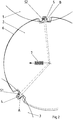
- a gear train of a rotary machine is shown schematically.
- a printing press was selected here as an example. So that's part of one Printing unit drive shown.
- drive gears 1, 2 and 3 for printing unit cylinders of an offset printing unit are shown.
- a drive gear 1 is assigned to a plate cylinder, a drive gear 2 to a rubber cylinder and a drive gear 3 to a pressure cylinder.
- the drive gears 1-3 are in a driving connection, the drive from the pressure cylinder in the direction of the plate cylinder, ie from the drive gear 1 via the drive gear 2 to the drive gear 1.
- Fig. 2 the meshing between the drive gears 1 to 3 are enlarged and shown in more detail.
- the drive gear 2 of the blanket cylinder is in drive connection with the drive gear 1 of the plate cylinder and the drive gear 3 of the printing cylinder. In the drive direction from the drive gear 3, this rests on the drive gear 2 or a tooth 4 at point A. Depending on the drive direction, the drive gear 2 rests with a tooth 5 on the drive gear 1 at point B.
- these flank systems in points A and B are retained during the entire printing process.
- different play constellations may result from different diameters of the blanket cylinder and plate cylinder or from different paper thicknesses as a result of the friction on the cylinder surfaces.
- the impression cylinder can drive the blanket cylinder over the paper surface as a result of the friction between the paper and the blanket, in which case the blanket cylinder would rotate more quickly and the drive gear 2 would lead the drive gear 3. Then the tooth 4 would overcome an (exaggerated) drive play S1 and rest on the other side of the tooth gap. None changes for the tooth engagement between the blanket cylinder and plate cylinder.
- a comparable condition results if the surface or the diameter of the rubber cylinder is relatively too large relative to the plate cylinder due to a thicker rubber blanket or underlay sheet. Then the plate cylinder would be driven over the surface of the blanket cylinder and the drive gear 1 would lead the drive gear 2. The result of this is that a drive play S2 (also shown in an exaggerated manner) between tooth 5 and the toothing of drive gear 1 is overcome and tooth 5 engages the other side of the tooth gap concerned.
- the drive play S1, S2 should now be eliminated, as shown in FIG. 2, with the aid of an idler gear 6.
- the idler gear 6 is arranged essentially coaxially with the drive gear 2 on the axis of the rubber cylinder. It is loaded with the aid of the force of a spring 7, shown schematically here, and pressed in the direction of the drive play S1, S2.
- the idler gear 6 is in each case on the flank which is free with respect to the torque transmission in the tooth engagement between the drive gears 1 or 2 and 2 or 3.
- the drive gear 2 of the rubber cylinder on the drive gears 1 and 3 is kept in constant contact. The game is no longer bridged.
- Fig. 3 the drive gear 1 of the plate cylinder and the drive gear 3 of the printing cylinder are shown.
- the impeller 6 is arranged between the two. This is evident from the type of flank system that faces away from the drive direction.
- the idler gear 6 is arranged on a bearing block 8 fixed to the frame. Connected to the bearing block 8 in turn a bearing lever 9 is pivotally arranged.
- the bearing lever 9 can be set against the bearing block 8 by means of a clamping device 10, which contains a spring assembly and can be preloaded with a clamping screw.
- the idler gear 6 is rotatably mounted on the bearing lever 9.
- the tensioning device 10 moves the bearing lever 9 with the idler gear 6 due to its set pretension a pivot point 11 on the frame fixed bracket 8 such that it is drawn into the gap between the drive wheels 1 and 3.
- the tooth flanks facing away from the drive on the drive toothed wheels 1 and 3 come into contact with the toothing of the side gear 6 at the tooth engagements C and D.
- the drive gear 2 is arranged on a shaft journal 12 in a frame part 13.
- the idler gear 6 is arranged on bearing devices 14 coaxially with the drive gear 2.
- the bearing devices 14 are described in FIG. 5 below.
- the idler gear 6 is also connected to a bearing flange 15, which engages around the shaft journal 12 without contact on the end face.
- the bearing flange 15 is bell-shaped and carries a bearing 16 on its side used by the idler gear 6.
- the bearing 16 is in turn arranged on a collar 17 which is connected to the bearing lever 9.
- the bearing lever 9 is arranged on the bearing block 8 fixed to the frame by means of a stay bolt 18 which forms the pivot axis 11.
- the tensioning device 10 with the spring assembly engages in an eye 20.
- the idler gear can be displaced in its axial position relative to the drive gear 2 by pivoting about the bearing axis 11.
- the idler gear 6 remains freely rotatable on the bearing 16.
- Each bearing device 14 has a retaining bolt 21 fastened in the drive gear 2.
- the retaining bolt 21 extends through the idler gear 6 in openings 19.
- the openings 19 have a slightly larger diameter than the retaining bolts 21 in order to allow a relative movement between the idler gear 6 and the drive gear 2 or to enable the retaining bolt 21.
- the openings 19 can be provided in guide bushings.
- axial bearings 22 are arranged on both end faces of the idler gear 6. An axial bearing 22 is therefore arranged between the idler gear 6 and the drive gear 2 and between the screw connection 23 of the bearing pin 21 and the idler gear 6.
- the axial bearings 22 each have flat bearing disks 24 and 25, or 26 and 27 on the inner bearing disks 25, 26 can be secured against displacement by the bushings in the openings 19.
- the outer bearing disks 24, 27 are centered on shoulders of the retaining bolt 21. This allows the respective cage of the axial bearing 22 to rotate and move radially to the bearing disks 24 to 27 without the bearing being able to shift. In this way, the idler gear 6 is kept at an exactly constant distance from the drive gear 2 in all movement states.
- the device has the following functionality:
- the idler gear 6 can be permanently held in a position under the force of the tensioning device 10 via its prestressed spring assembly in which the axes of rotation of the drive gear 2 and the idler gear 6 do not overlap.
- the idler gear 6 lies on the tooth flanks opposite the driving tooth flanks of the drive gear wheels 1 and 3.
- the drive gears 1 and 3 are quasi clamped in relation to the drive gear 2.
- the relative position between the drive gear 2 and the idler gear 6 is shown in more detail in FIG. 2.
- the adjustable preload of the tensioning device 10 makes it possible to provide different auxiliary forces to compensate for drive play between the drive gear 2 and the idler gear 6. This makes it possible to influence the operating conditions of the rotary machine and the load on the drive train.
- the type of suspension of the idler gear 6 relative to the drive gear 2 is of course possible in a different way than shown in the aforementioned example.
- the idler gear 6 can also be fastened to the drive gear 2 on a linearly guided adjusting device.
- the drive clearances are relatively small, a sufficiently precise adjustment of the idler gear 6 is also possible with the aid of the bearing lever 9 mentioned, the displacement of which is not exceeded by a maximum amount due to the pivoting radius of the bearing lever 9 out of the necessary engagement space.
- the device can be arranged very compactly in the manner shown and can also be easily assembled.
- the drive gear 2 only needs to be changed slightly, so that the effort for installing the device would require greater effort.
Landscapes
- Engineering & Computer Science (AREA)
- Mechanical Engineering (AREA)
- Gear Transmission (AREA)
- Rotary Presses (AREA)
- Testing Of Devices, Machine Parts, Or Other Structures Thereof (AREA)
- Accessory Devices And Overall Control Thereof (AREA)
- Character Spaces And Line Spaces In Printers (AREA)
Abstract
Description
Die Erfindung betrifft eine Vorrichtung zur Beseitigung von Antriebsspiel in einem Druckwerk nach dem Oberbegriff des Patentanspruches 1.The invention relates to a device for eliminating drive play in a printing unit according to the preamble of
In Zahnradgetrieben von Druckmaschinen ist nicht immer sichergestellt, daß die Antriebsleistung vollständig über die Zahnräder übertragen wird. Durch unterschiedliche Verhältnisse kann es dazu kommen, daß durch die Oberflächenreibung zwischen den Zylindern eines Druckwerkes auch dort ein erheblicher Teil der Antriebsleistung übertragen wird und es dadurch zu einem unkontrollierten Wechseln der Flankenanlage im Zahnradgetriebe kommt. Bedingt durch derartige Flankenwechsel, die sich im Rahmen der Größenordnung des Spieles des Zahnradgetriebes bewegen, ergeben sich Ungenauigkeiten beim Ausdruck der Bilder.In gearboxes of printing machines, it is not always ensured that the drive power is transmitted entirely via the gearwheels. Due to different conditions, it can happen that the surface friction between the cylinders of a printing unit transfers a considerable part of the drive power there too, and this leads to an uncontrolled change of the flank system in the gear transmission. Due to such flank changes, which are within the order of magnitude of the play of the gear transmission, there are inaccuracies in the printing of the images.
Zur Vermeidung von Spiel in Zahnradgetrieben sind beispielsweise angefederte Beiläuferräder eingesetzt worden. Bekannt geworden ist ein solches Getriebe aus dem deutschen Gebrauchsmuster 81 09 324. Diese Veröffentlichung zeigt einen spielfreien Zahnradantrieb für Druckmaschinen. Hierbei ist auf einem Bund eines Antriebszahnrades ein Zahnradring verdrehbar angeordnet. Der Zahnradring ist mittels einer angefederten Kugelrastverbindung in seiner Drehlage gehalten. Bei Lageveränderungen kann der Zahnradring sich gegen die Kraft der Federn bewegen. Da die Verzahnung des Zahnradringes mittels der Kugelrastverbindungen mit leichtem Versatz gegenüber dem Hauptzahnrad gehalten wird ergibt sich automatisch eine angefederte Spielbeseitigung im Zahneingriff Die Spielbeseitigung setzt hier aber voraus, daß das Antriebsspiel an zwei Zahneingriffen des Hauptzahnrades in Umlaufrichtung gleich liegt, sodaß in der Regel der Zahnradring nur an einem der benachbarten Antriebszahnräder an einer vom Antrieb freien Zahnflanke anliegt.To avoid play in gear transmissions, sprung idler wheels have been used, for example. Such a transmission has become known from German utility model 81 09 324. This publication shows a backlash-free gear drive for printing machines. Here, a gear ring is rotatably arranged on a collar of a drive gear. The gear ring is held in its rotational position by means of a spring-loaded ball detent connection. If the position changes, the gear ring can move against the force of the springs. Since the toothing of the gear ring is held by means of the ball detent connections with a slight offset relative to the main gear, there is automatically a sprung clearance elimination in the tooth engagement abuts only on one of the adjacent drive gears on a tooth flank free of the drive.
Bei den geschilderten teilweise undefinierten Reibungsverhältnissen innerhalb eines Druckwerkes kann es aber dazu kommen, daß das Antriebsspiel entgegengesetzt an beiden Zahneingriffen herausgedrückt wird. Außerdem können die Kräfte, die zum Wechsel der Zahnflanken führen, relativ hoch sein, so daß eine einfache Kugelrastverbindung, die zudem nur auf eine Zahnflanke wirkt, nicht ausreicht, um den Flankenwechsel zu verhindern.In the case of the partially undefined friction conditions described within a printing unit, however, it can happen that the drive play is pressed out in opposite directions on both tooth meshings. In addition, the forces that lead to the change of the tooth flanks can be relatively high, so that a simple ball catch connection, which also acts only on one tooth flank, is not sufficient to prevent the flank change.
Ziel der Erfindung ist es, einen unkontrollierten Zahnflankenwechsel in einem Druckwerkantrieb zu verhindern und eine einstellbare, den unterschiedlichen Bedürfnissen von Druckprozessen anpaßbare Vorrichtung zur Spielbeseitigung zu schaffen.The aim of the invention is to prevent an uncontrolled tooth flank change in a printing unit drive and to create an adjustable device for eliminating play that can be adapted to the different needs of printing processes.
Aufgabe der Erfindung ist es eine Vorrichtung zur Spielbeseitigung zu schaffen, die die Nachteile des Standes der Technik überwindet.The object of the invention is to provide a device for eliminating play which overcomes the disadvantages of the prior art.
Die Lösung der Aufgabe gestaltet sich nach dem Kennzeichen des Patentanspruches 1. Durch die Merkmale der Anfederung eines Beiläuferzahnrades ist sichergestellt, daß permanent eine Spielbeseitigung gegeben ist. Außerdem ist die Kraft zur Überwindung des Antriebsspieles einstellbar. Weiterhin genügt die Vorrichtung den hohen Anforderungen bei der Übertragung von Antriebsleistungen in einem Druckwerk.The solution of the task is designed according to the characterizing part of
Im folgenden wird anhand von zeichnerischen Darstellungen ein Ausführungsbeispiel näher beschrieben.An exemplary embodiment is described in more detail below with the aid of drawings.
Darin zeigen:
- Fig. 1
- eine schematische Darstellung eines Druckwerkantriebes,
- Fig. 2
- eine schematische Darstellung der Zahneingriffe,
- Fig. 3
- eine vereinfachte Darstellung der Vorrichtung zur Spielbeseitigung,
- Fig. 4
- einen Schnitt durch die Vorrichtung zur Spielbeseitigung und
- Fig. 5
- eine Detaildarstellung der Halterung des Beiläuferzahnrades.
- Fig. 1
- a schematic representation of a printing unit drive,
- Fig. 2
- a schematic representation of the meshing,
- Fig. 3
- a simplified representation of the device for eliminating play,
- Fig. 4
- a section through the device for eliminating the game and
- Fig. 5
- a detailed view of the bracket of the idler gear.
In Fig. 1 ist schematisch ein Zahnradzug einer Rotationsmaschine dargestellt. Hier wurde beispielhaft ein Druckmaschine ausgewählt. Damit ist also ein Teil eines Druckwerksantriebes dargestellt. Hierbei sind Antriebszahnräder 1, 2 und 3 für Druckwerkszylinder eines Offsetdruckwerkes gezeigt. Dabei ist einem Plattenzylinder ein Antriebszahnrad 1, einem Gummizylinder ein Antriebszahnrad 2 und einem Druckzylinder ein Antriebszahnrad 3 zugeordnet. Die Antriebszahnräder 1 - 3 stehen in treibender Verbindung, wobei der Antrieb vom Druckzylinder in Richtung zum Plattenzylinder, d.h. vom Antriebszahnrad 1 über das Antriebszahnrad 2 zum Antriebszahnrad 1 erfolgt.In Fig. 1, a gear train of a rotary machine is shown schematically. A printing press was selected here as an example. So that's part of one Printing unit drive shown. Here drive
In Fig. 2 sind die Zahneingriffe zwischen den Antriebszahnrädern 1 bis 3 vergrößert und detaillierter bzw. dargestellt. Das Antriebszahnrad 2 des Gummizylinders steht mit dem Antriebszahnrad 1 des Plattenzylinders und dem Antriebszahnrad 3 des Druckzylinders in Antriebsverbindung. In Antriebsrichtung vom Antriebszahnrad 3 aus liegt dieses am Antriebszahnrad 2 bzw. einem Zahn 4 im Punkt A an. Entsprechend der Antriebsrichtung liegt das Antriebszahnrad 2 mit einem Zahn 5 am Antriebszahnrad 1 im Punkt B an. Zum exakten Transport des zu druckenden Bildes ist es erforderlich, daß diese Flankenanlagen in den Punkten A und B jeweils während des gesamten Druckprozesses erhalten bleiben. Gegebenenfalls kann aber durch unterschiedliche Durchmesser von Gummizylinder und Plattenzylinder bzw. durch unterschiedliche Papierstärken in Folge der Reibung an den Zylinderoberflächen sich eine andere Spielkonstellation ergeben. Beispielsweise kann vom Druckzylinder aus der Gummizylinder über die Papieroberfläche in Folge der Reibung zwischen dem Papier und dem Gummituch angetrieben werden, wobei dann der Gummizylinder schneller umlaufen würde und das Antriebszahnrad 2 gegenüber dem Antriebszahnrad 3 voreilen wurde. Dann wurde der Zahn 4 ein (übertrieben dargestelltes) Antriebsspiel S1 überwinden und an der anderen Seite der Zahnlücke anliegen. Für den Zahneingriff zwischen Gummizylinder und Plattenzylinder ändert sich dabei nichts.In Fig. 2, the meshing between the
Ein vergleichbarer Zustand ergibt sich, wenn die Oberfläche bzw. der Durchmesser des Gummizylinders relativ zum Plattenzylinder durch ein dickeres Gummituch oder Unterlagebogen relativ zu groß ist. Dann würde der Plattenzylinder über die Oberfläche des Gummizylinders angetrieben und das Antriebszahnrad 1 wurde gegenüber dem Antriebszahnrad 2 voreilen. Das führt dazu, daß ein (ebenfalls übertrieben dargestelltes) Antriebsspiel S2 zwischen dem Zahn 5 und der Verzahnung des Antriebszahnrades 1 überwunden wird und der Zahn 5 sich an der anderen Seite der betroffenen Zahnlücke anlegt.A comparable condition results if the surface or the diameter of the rubber cylinder is relatively too large relative to the plate cylinder due to a thicker rubber blanket or underlay sheet. Then the plate cylinder would be driven over the surface of the blanket cylinder and the
In beiden Fällen tritt eine unerwünschte Relativbewegung der das Druckbild überlagernden Oberflächen auf, die zu Qualitätseinbußen bzw. nicht akzeptablen Druckergebnissen führt.In both cases, an undesired relative movement of the surfaces overlaying the print image occurs, which leads to a loss of quality or unacceptable print results.
Wesentlich ist weiterhin, daß bei der Drehung der Zylinder im Bereich von auf diesen vorhandenen Zylinderkanälen, die für die Halterung von Druckplatten, Gummitüchern und die Anordnung von Greifersytemen für den Bogentransport notwendig sind, die Reibkräfte zwischen den Druckwerkszylindern kurzzeitig wegfallen. Damit ergibt sich ein Drehstoß, der sich je nach der oben geschilderten Ausgangssituation mit Relativbewegungen im Rahmen des Antriebsspieles S1, S2 auf die Antriebszahnräder 1, 2, 3 auswirkt.It is also important that when the cylinders are rotated in the area of the cylinder channels present on them, which are necessary for the mounting of printing plates, blankets and the arrangement of gripper systems for sheet transport, the frictional forces between the printing unit cylinders are briefly eliminated. This results in a rotary impact which, depending on the starting situation described above, affects the
Um dies zu vermeiden, soll nun, wie in Fig. 2 dargestellt, mit Hilfe eines Beiläuferzahnrades 6 das Antriebsspiel S1, S2 bleiben beseitigt werden. Dazu ist das Beiläuferzahnrad 6 im wesentlichen koaxial zum Antriebszahnrad 2 auf der Achse des Gummizylinders angeordnet. Es wird mit Hilfe der Kraft einer hier schematisch dargestellten Feder 7 belastet und in Richtung des Antriebsspieles S1, S2 gedrückt. Dadurch liegt das Beiläuferzahnrad 6 jeweils an der bezüglich der Momentenübertragung freien Flanke im Zahneingriff zwischen den Antriebszahnrädern 1 bzw. 2 und 2 bzw. 3 an. Als Ergebnis der Anstellung des Beiläuferzahnrades 6 wird das Antriebszahnrad 2 des Gummizylinders an den Antriebszahnrädern 1 und 3 dauernd in Anlage gehalten. Eine Spielüberbrückung findet nicht mehr statt.In order to avoid this, the drive play S1, S2 should now be eliminated, as shown in FIG. 2, with the aid of an
Die konstruktive Ausführung der entsprechenden Vorrichtung wird im folgenden gezeigt.The design of the corresponding device is shown below.
In Fig. 3 sind das Antriebszahnrad 1 des Plattenzylinders und das Antriebszahnrad 3 des Druckzylinders dargestellt. Zwischen beiden ist das Beiläuferrad 6 angeordnet. Dies ist ersichtlich an der Art der Flankenanlage, die von der Antriebsrichtung abgewandt ist. Das Beiläuferrad 6 ist auf einem gestellfesten Lagerbock 8 angeordnet. Verbunden mit dem Lagerbock 8 wiederum ist schwenkbar ein Lagerhebel 9 angeordnet. Der Lagerhebel 9 kann mittels einer Spannvorrichtung 10, die ein Federpaket enthält und mit einer Spannschraube vorspannbar ist, gegenüber dem Lagerbock 8 angestellt werden. Auf dem Lagerhebel 9 ist das Beiläuferrad 6 drehbar gelagert. Die Spannvorrichtung 10 bewegt aufgrund ihrer eingestellten Vorspannung den Lagerhebel 9 mit dem Beiläuferrad 6 um einen Schwenkpunkt 11 auf dem gestellfesten Lagerbock 8 derart, daß es in die Lücke zwischen Antriebsrad 1 und 3 hineingezogen wird. Dadurch kommen an den Zahneingriffen C und D jeweils die vom Antrieb abgewandten Zahnflanken auf den Antriebszahnrädern 1 und 3 mit der Verzahnung des Beiläuferrades 6 in Anlage.In Fig. 3, the
Die Halterung des Beiläuferrades 6 ist in Fig. 4 näher beschrieben. Das Antriebszahnrad 2 ist auf einem Wellenzapfen 12 in einem Gestellteil 13 angeordnet. Koaxial zum Antriebszahnrad 2 ist das Beiläuferzahnrad 6 auf Lagereinrichtungen 14 angeordnet. Die Lagereinrichtungen 14 werden in Fig. 5 weiter unten beschrieben. Das Beiläuferzahnrad 6 ist weiterhin mit einem Lagerflansch 15 verbunden, der den Wellenzapfen 12 stirnseitig berührungslos umgreift. Der Lagerflansch 15 ist glockenförmig ausgebildet und trägt an seiner vom Beiläuferzahnrad 6 angewandten Seite ein Lager 16. Das Lager 16 ist wiederum auf einem Bund 17 angeordnet, der mit dem Lagerhebel 9 verbunden ist. Der Lagerhebel 9 ist auf dem gestellfesten Lagerbock 8 mittels eines Stehbolzens 18 angeordnet, der die Schwenkachse 11 bildet. An dem dem Lager 16 gegenüberliegenden Ende des Lagerhebels 9 greift in einem Auge 20 die Spannvorrichtung 10 mit dem Federpaket an. Durch Einstellung des Federpakets mittels der Spannschraube der Spannvorrichtung 10 läßt sich also das Beiläuferrad durch Schwenken um die Lagerachse 11 in seiner Achslage relativ zum Antriebszahnrad 2 verlagern. Das Beiläuferrad 6 bleibt dabei auf dem Lager 16 frei drehbar.The mounting of the
In Fig. 5 ist eine von mehreren symmetrisch zum Antriebszahnrad 2 angeordneten Lagervorrichtungen 14 im Detail gezeigt. Jede Lagervorrichtung 14 weist einen im Antriebszahnrad 2 befestigten Haltebolzen 21 auf Der Haltebolzen 21 durchgreift das Beiläuferzahnrad 6 in Öffnungen 19. Die Öffnungen 19 weisen einen um ein geringes Maß größeren Durchmesser als die Haltebolzen 21 auf, um eine Relativbewegung zwischen Beiläuferzahnrad 6 und Antriebszahnrad 2 bzw. den Haltebolzen 21 zu ermöglichen. Die Öffnungen 19 können in Führungsbuchsen vorgesehen sein. Zur Sicherstellung einer immer exakt geführten Relativbewegung zwischen dem Beiläuferzahnrad 6 und dem Antriebszahnrad 2 sind Axiallager 22 jeweils an beiden Stirnseiten des Beiläuferzahnrades 6 angeordnet. Es ist also jeweils ein Axiallager 22 zwischen dem Beiläuferzahnrad 6 und dem Antriebszahnrad 2 sowie zwischen der Verschraubung 23 des Lagerbolzens 21 und dem Beiläuferzahnrad 6 angeordnet. Die Axiallager 22 weisen jeweils flache Lagerscheiben 24 und 25, bzw. 26 und 27 auf Die inneren Lagerscheiben 25, 26 können gegen Verschiebung durch die Buchsen in den Öffnungen 19 gesichert sein. Die äußeren Lagerscheiben 24, 27 sind auf Absätzen des Haltebolzens 21 zentriert. Dadurch kann der jeweilige Käfig der Axiallager 22 sich rotierend und radial zu den Lagerscheiben 24 bis 27 bewegen, ohne daß die Lagererung sich verschieben kann. Auf diese Weise wird das Beiläuferzahnrad 6 in allen Bewegungszuständen in exakt konstantem Abstand zum Antriebszahnrad 2 gehalten.5 shows one of
Die Vorrichtung weist folgende Funktionsweise auf:The device has the following functionality:
Durch die Halterung des Beiläuferzahnrades 6 mittels des Lagerflansches 15, der relativ zum Antriebszahnrad 2 schwenkbar ist, ergibt sich bei Rotation des Antriebszahnrades 2 eine permanente Relativbewegung in radialer Richtung zwischen Antriebszahnrad 2 und Beiläuferzahnrad 6. Diese Relativbewegung, die sich in der Art einer Taumelbewegung darstellt, wird durch die Axiallager 22 in den Lagereinrichtungen 14 ermöglicht, wobei sich das Beiläuferrad 6 im Bereich der Öffnungen 19 gegenüber dem Antriebszahnrad 2 bewegen kann. Die Axiallager 22 halten einerseits das Beiläuferzahnrad 6 in exakt paralleler Orientierung zum Antriebszahnrad 2 lassen aber auf der anderen Seite eine Relativbewegung parallel und radial zum Antriebszahnrad 2 zu. Dadurch kann das Beiläuferzahnrad 6 unter der Kraft der Spannvorrichtung 10 über deren vorgespanntes Federpaket permanent in einer Lage gehalten werden, in der sich die Drehachsen von Antriebszahnrad 2 und Beiläuferzahnrad 6 nicht überdecken. Dabei liegt das Beiläuferzahnrad 6 an den den treibenden Zahnflanken der Antriebszahnräder 1 und 3 gegenüberliegenden Zahnflanken an. Auf diese Weise ist der Spielausgleich im Antriebszug der Antriebszahnräder 1 bis 3 möglich. Durch die Anlage des Beiläuferzahnrades 2 an den nicht von dem Antriebszahnrad 2 belasteten Zahnflanken werden die Antriebszahnräder 1 und 3 quasi gegenüber dem Antriebszahnrad 2 eingespannt. Die Relativlage zwischen dem Antriebszahnrad 2 und dem Beiläuferzahnrad 6 ist in Fig. 2 näher dargestellt. Durch die einstellbare Vorspannung der Spannvorrichtung 10 sind unterschiedliche Beistellkräfte zum Ausgleich von Antriebsspiel zwischen dem Antriebszahnrad 2 und dem Beiläuferzahnrad 6 möglich. Damit ist eine Einflußnahme auf die Betriebsbedingungen der Rotationsmaschine und die Belastung des Antriebszuges möglich.By holding the
Die Art der Aufhängung des Beiläuferzahnrades 6 relativ zum Antriebszahnrad 2 ist selbstverständlich auf andere Art möglich als in dem vorgenannten Beispiel aufgezeigt. Beispielsweise kann das Beiläuferzahnrad 6 an dem Antriebszahnrad 2 auch auf einer linear geführten Anstellvorrichtung befestigt sein. Da die Antriebsspiele aber relativ gering sind, ist auch mit Hilfe des genannten Lagerhebels 9 eine ausreichend genaue Verstellung des Beiläuferzahnrades 6 möglich, wobei dessen Verlagerung durch den Schwenkradius des Lagerhebels 9 aus dem notwendigen Eingriffsraum heraus über ein maximales Maß nicht überschreiten wird. Die Vorrichtung ist aufdie dargestellte Weise sehr kompakt anzuordnen und kann auch einfach montiert werden. Das Antriebszahnrad 2 muß nur wenig verändert werden, so daß der Aufwand für den Einbau der Vorrichtung größere Aufwände erfordern würde.The type of suspension of the
- 11
- AntriebszahnradDrive gear
- 22nd
- AntriebszahnradDrive gear
- 33rd
- AntriebszahnradDrive gear
- 44th
- Zahntooth
- 55
- Zahntooth
- 66
- BeiläuferzahnradIdler gear
- 77
- Federfeather
- 88th
- LagerbockBearing block
- 99
- LagerhebelBearing lever
- 1010th
- SpannvorrichtungJig
- 1111
- SchwenkpunktPivot point
- 1212th
- WellenzapfenShaft journal
- 1313
- GestellteilFrame part
- 1414
- LagereinrichtungStorage facility
- 1515
- LagerflanschBearing flange
- 1616
- Lagercamp
- 1717th
- BundFederation
- 1818th
- StehbolzenStud bolts
- 1919th
- Öffnungopening
- 2020th
- Augeeye
- 2121
- HaltebolzenRetaining bolt
- 2222
- AxiallagerThrust bearing
- 2323
- VerschraubungScrew connection
- 2424th
- LagerscheibeBearing washer
- 2525th
- LagerscheibeBearing washer
- 2626
- LagerscheibeBearing washer
- 2727
- LagerscheibeBearing washer
- A, BA, B
- WälzpunktPitch point
- S1, S2S1, S2
- AntriebsspielDrive play
- C, DC, D
- ZahneingriffMeshing
Claims (9)
dadurch gekennzeichnet,
daß ein Beiläuferzahnrad (6) auf einem Antriebszahnrad (2), das mit zwei weiteren Antriebszahnraädern (1, 3) in Antriebsverbindung steht, angeordnet ist, und daß Mittel vorgesehen sind, mittels derer das Beiläuferrad (6) auf dem Antriebszahnrad (2) verdrehbar und verschiebbar befestigt und gegen die freien Zahnflanken der beiden weiteren Antriebszahnräder (1, 3) anstellbar ist.Device for compensating for play in drive trains of rotary machines with a plurality of drive gears connected in series and means for loading idler gears against unloaded tooth flanks of drive gears supported on one of the drive gears,
characterized by
that an idler gear (6) is arranged on a drive gear (2) which is in drive connection with two further drive gearwheels (1, 3), and that means are provided by means of which the idler gear (6) can be rotated on the drive gear (2) and slidably attached and adjustable against the free tooth flanks of the two further drive gears (1, 3).
dadurch gekennzeichnet,
daß die Mittel zum drehbaren und verschiebbaren befestigen des Beiläuferzahnrades (6) als Lagereinrichtungen (14) auf dem Antriebszahnrad (2) derart vorgesehen sind, daß das Beiläuferrad (6) koaxial oder annähernd koaxial und parallel zum Antriebszahnrad (2) an diesem geführt und in einer Ebene parallel zu diesem sowohl in geringem Umfang drehbar als auch verschiebbar ist.Device according to claim 1,
characterized by
that the means for rotatably and slidably attaching the idler gear (6) are provided as bearing means (14) on the drive gear (2) such that the idler gear (6) is guided coaxially or approximately coaxially and parallel to the drive gear (2) and in a plane parallel to it is both rotatable and displaceable to a small extent.
dadurch gekennzeichnet,
daß die Lagereinrichtungen (14) als in der Form einer Axiallagerlagerung ausgeführt sind, wobei deren Lagerflächen eben sind.Device according to claim 2,
characterized by
that the bearing devices (14) are designed as in the form of an axial bearing bearing, the bearing surfaces of which are flat.
dadurch gekennzeichnet,
daß die Axiallagerlagerung mit wenigstens drei Lagerpunkten ausgeführt ist, die mit je zwei Axiallagern (22) und paarweise ebene Lagerscheiben (24, 25; 26, 27) auf mit dem Antriebszahnrad (2) verbundenen Haltebolzen (21) versehen sind und das Beiläuferrad (6) zwischen den Axiallagern (22) angeordnet ist.Device according to claim 3,
characterized by
that the thrust bearing is designed with at least three bearing points, which are each provided with two thrust bearings (22) and pairs of flat bearing washers (24, 25; 26, 27) on retaining bolts (21) connected to the drive gear (2) and the idler gear (6 ) is arranged between the thrust bearings (22).
dadurch gekennzeichnet,
daß die Haltebolzen (21) durch Öffnungen (28) im Beiläuferrad (6) greifen und die Öffnungen (28) einen größeren Durchmesser als die Haltebolzen (21) aufweisen.Device according to claims 1 to 4,
characterized by
that the retaining bolts (21) engage through openings (28) in the idler gear (6) and the openings (28) have a larger diameter than the retaining bolts (21).
dadurch gekennzeichnet,
daß die Mittel zum Anstellen des Beiläuferzahnrades (6) eine gestellfeste Abstützung und einstellbare Stellmittel zur Verschiebung des Beiläuferzahnrades (6) gegenüber dem Antriebszahnrad (2) in oder annähernd in Richtung der Winkelhalbierenden zwischen den Achsverbindungen zwischen dem Antriebszahnrad (2) und den weiteren Antriebszahnrädern (1, 3) aufweisen.Device according to claim 1,
characterized by
that the means for adjusting the idler gear (6) have a support fixed to the frame and adjustable adjusting means for displacing the idler gear (6) with respect to the drive gear (2) in or approximately in the direction of the bisector between the axis connections between the drive gear (2) and the further drive gears ( 1, 3).
dadurch gekennzeichnet,
daß das Beiläuferzahnrad (6) drehbar auf einem Lagerhebel (9) gelagert ist, der auf einem gestellfesten Lagerbock (8) schwenkbar abgestützt ist, und daß zwischen dem Lagerbock (8) und dem Lagerhebel (9) die einstellbaren Stellmittel zur Verschiebung des Beiläuferzahnrades (6) vorgesehen sind.Apparatus according to claim 6,
characterized by
that the idler gear (6) is rotatably mounted on a bearing lever (9) which is pivotally supported on a bearing block (8) fixed to the frame, and that between the bearing block (8) and the bearing lever (9) the adjustable adjusting means for displacing the idler gear ( 6) are provided.
dadurch gekennzeichnet,
daß die einstellbaren Stellmittel als Spannvorrichtung (10) mit einstellbarer Vorspannung ausgeführt sind.Apparatus according to claim 6,
characterized by
that the adjustable adjusting means are designed as a tensioning device (10) with an adjustable preload.
dadurch gekennzeichnet,
daß die Spannvorrichtung (10) aus einem Federpaket, das sich auf dem Lagerhebel (9) abstützt, und einer das Federpaket belastenden Spannschraube besteht, die den Lagerhebel (9) durchgreift und in dem Lagerbock (8) verstellbar angeordnet ist.Device according to claim 8,
characterized by
that the tensioning device (10) consists of a spring assembly, which is supported on the bearing lever (9), and a tensioning screw loading the spring assembly, which passes through the bearing lever (9) and is arranged in an adjustable manner in the bearing block (8).
Applications Claiming Priority (2)
| Application Number | Priority Date | Filing Date | Title |
|---|---|---|---|
| DE19540573A DE19540573C1 (en) | 1995-10-31 | 1995-10-31 | Device for compensating play in rotary printing machines |
| DE19540573 | 1995-10-31 |
Publications (2)
| Publication Number | Publication Date |
|---|---|
| EP0771648A1 true EP0771648A1 (en) | 1997-05-07 |
| EP0771648B1 EP0771648B1 (en) | 1998-10-21 |
Family
ID=7776282
Family Applications (1)
| Application Number | Title | Priority Date | Filing Date |
|---|---|---|---|
| EP96115260A Expired - Lifetime EP0771648B1 (en) | 1995-10-31 | 1996-09-24 | Device for taking up backlash in a printing machine |
Country Status (4)
| Country | Link |
|---|---|
| EP (1) | EP0771648B1 (en) |
| JP (1) | JPH09177903A (en) |
| AT (1) | ATE172406T1 (en) |
| DE (2) | DE19540573C1 (en) |
Cited By (1)
| Publication number | Priority date | Publication date | Assignee | Title |
|---|---|---|---|---|
| EP0943433A1 (en) * | 1998-03-16 | 1999-09-22 | Grapha-Holding Ag | Printing unit for a printing machine, particularly rotary offset printing machine |
Families Citing this family (6)
| Publication number | Priority date | Publication date | Assignee | Title |
|---|---|---|---|---|
| DE19716283A1 (en) * | 1997-04-18 | 1998-10-22 | Koenig & Bauer Albert Ag | Cylinder arrangement for web-fed rotary printing machines |
| US6335392B1 (en) | 1998-10-21 | 2002-01-01 | Sumitomo Rubber Industries, Ltd. | Outsole of shoes |
| DE10023682A1 (en) * | 2000-05-16 | 2001-11-22 | Roland Man Druckmasch | Drive of a feeder for a sheet processing machine |
| DE102007020225A1 (en) * | 2007-04-28 | 2008-10-30 | Koenig & Bauer Aktiengesellschaft | Synchronizing device for rotary motion of rotation bodies has individual drives receiving position signals from intended value setters |
| DE102007025752A1 (en) * | 2007-06-01 | 2008-12-04 | Manroland Ag | Powered assembly of a printing press |
| DE102009057849A1 (en) | 2009-12-10 | 2011-06-16 | Heidelberger Druckmaschinen Ag | Offset lithographic printing machine, has toothed wheel pivotable relative to another toothed wheel such that driving power is transferable from former toothed wheel over third toothed wheel to latter toothed wheel |
Citations (3)
| Publication number | Priority date | Publication date | Assignee | Title |
|---|---|---|---|---|
| US3407727A (en) * | 1966-03-23 | 1968-10-29 | Maschf Augsburg Nuernberg Ag | Supplementary driving gear arrangement for multi-color sheet-fed rotary printing presses |
| GB1135164A (en) * | 1966-04-16 | 1968-12-04 | Albert Schnellpressen | Improvements in or relating to drive mechanisms for the printing mechanisms of rotary printing presses |
| GB1214422A (en) * | 1968-04-20 | 1970-12-02 | Maschf Augsburg Nuernberg Ag | Improvements in or relating to rotary offset printing machines |
Family Cites Families (3)
| Publication number | Priority date | Publication date | Assignee | Title |
|---|---|---|---|---|
| JPS4831470B1 (en) * | 1970-05-26 | 1973-09-29 | ||
| DE8109324U1 (en) * | 1981-03-30 | 1983-03-10 | M.A.N.- Roland Druckmaschinen AG, 6050 Offenbach | Backlash-free gear drive for printing machines |
| JPS5881263A (en) * | 1981-10-30 | 1983-05-16 | ゼロツクス・コ−ポレ−シヨン | Opposed spring type backlash preventive divided gear |
-
1995
- 1995-10-31 DE DE19540573A patent/DE19540573C1/en not_active Expired - Fee Related
-
1996
- 1996-09-24 DE DE59600701T patent/DE59600701D1/en not_active Expired - Fee Related
- 1996-09-24 EP EP96115260A patent/EP0771648B1/en not_active Expired - Lifetime
- 1996-09-24 AT AT96115260T patent/ATE172406T1/en not_active IP Right Cessation
- 1996-10-30 JP JP8288760A patent/JPH09177903A/en active Pending
Patent Citations (3)
| Publication number | Priority date | Publication date | Assignee | Title |
|---|---|---|---|---|
| US3407727A (en) * | 1966-03-23 | 1968-10-29 | Maschf Augsburg Nuernberg Ag | Supplementary driving gear arrangement for multi-color sheet-fed rotary printing presses |
| GB1135164A (en) * | 1966-04-16 | 1968-12-04 | Albert Schnellpressen | Improvements in or relating to drive mechanisms for the printing mechanisms of rotary printing presses |
| GB1214422A (en) * | 1968-04-20 | 1970-12-02 | Maschf Augsburg Nuernberg Ag | Improvements in or relating to rotary offset printing machines |
Cited By (2)
| Publication number | Priority date | Publication date | Assignee | Title |
|---|---|---|---|---|
| EP0943433A1 (en) * | 1998-03-16 | 1999-09-22 | Grapha-Holding Ag | Printing unit for a printing machine, particularly rotary offset printing machine |
| US6314881B1 (en) | 1998-03-16 | 2001-11-13 | Grapha-Holding Ag | Printing group for a printing press |
Also Published As
| Publication number | Publication date |
|---|---|
| DE59600701D1 (en) | 1998-11-26 |
| ATE172406T1 (en) | 1998-11-15 |
| JPH09177903A (en) | 1997-07-11 |
| EP0771648B1 (en) | 1998-10-21 |
| DE19540573C1 (en) | 1996-11-07 |
Similar Documents
| Publication | Publication Date | Title |
|---|---|---|
| DE19614397C2 (en) | Drive with register device for a printing unit of a web-fed rotary printing press | |
| DE1951427C3 (en) | Gearbox that translates into slow speed | |
| DE10066068A1 (en) | Drive of a rotating component | |
| DE102008046792A1 (en) | Printing machine with bearer rings | |
| EP0549884B1 (en) | Device for gear train separation | |
| DE19715026B4 (en) | Elastic drive for printing presses | |
| DE19540573C1 (en) | Device for compensating play in rotary printing machines | |
| DE4012965C1 (en) | Device for the on, off and setting of application rollers | |
| EP1310360A2 (en) | Flexographic printing machine with alternative manual and automatic applicable ink transfer rollers | |
| DE4430625B4 (en) | Bearing unit for a roller arrangement | |
| DE2829895C2 (en) | Angular gear for vehicle steering | |
| EP0683043B1 (en) | Impression cylinder of a rotary web printing machine | |
| DE3317746C2 (en) | Printing mechanism and method of printing | |
| CH687244A5 (en) | Device for method of two camps Boecken mounted on slides. | |
| DE2720219A1 (en) | DRIVE DEVICE FOR A ROLLER DRIVEN ON THE SLEEVE | |
| EP0172412A2 (en) | Sheet transfer cylinder in sheet-fed rotary presses | |
| DE2452650B1 (en) | One-way clutch with non-round clamping bodies | |
| DE2921153A1 (en) | DEVICE FOR SETTING THE PAGE AND PERIODIC REGISTER IN ROTARY PRINTING MACHINES | |
| DE4447862C2 (en) | Gear train separation device | |
| DE102008023333A1 (en) | Transfer drum for conveying a sheet in a printing machine | |
| EP1984181B1 (en) | Printing cylinder coupling | |
| DE4436584C2 (en) | Plate cylinder storage | |
| EP0508113A1 (en) | Device for the rapid precise clamping and tensioning of printing plates on the forme cylinder of a printing press | |
| DE2926765A1 (en) | DEVICE FOR SUPPRESSING BENDING VIBRATIONS IN ROTATIONAL OFFSET PRINTING MACHINES | |
| DE10234830A1 (en) | Sheet-fed rotary printing press has gear train which drives each form cylinder and corresponding transfer cylinder, through switchable speed-change gear mechanism |
Legal Events
| Date | Code | Title | Description |
|---|---|---|---|
| PUAI | Public reference made under article 153(3) epc to a published international application that has entered the european phase |
Free format text: ORIGINAL CODE: 0009012 |
|
| 17P | Request for examination filed |
Effective date: 19961009 |
|
| AK | Designated contracting states |
Kind code of ref document: A1 Designated state(s): AT CH DE FR GB IT LI NL |
|
| GRAG | Despatch of communication of intention to grant |
Free format text: ORIGINAL CODE: EPIDOS AGRA |
|
| GRAG | Despatch of communication of intention to grant |
Free format text: ORIGINAL CODE: EPIDOS AGRA |
|
| GRAH | Despatch of communication of intention to grant a patent |
Free format text: ORIGINAL CODE: EPIDOS IGRA |
|
| 17Q | First examination report despatched |
Effective date: 19980121 |
|
| GRAH | Despatch of communication of intention to grant a patent |
Free format text: ORIGINAL CODE: EPIDOS IGRA |
|
| GRAA | (expected) grant |
Free format text: ORIGINAL CODE: 0009210 |
|
| AK | Designated contracting states |
Kind code of ref document: B1 Designated state(s): AT CH DE FR GB IT LI NL |
|
| PG25 | Lapsed in a contracting state [announced via postgrant information from national office to epo] |
Ref country code: NL Free format text: LAPSE BECAUSE OF FAILURE TO SUBMIT A TRANSLATION OF THE DESCRIPTION OR TO PAY THE FEE WITHIN THE PRESCRIBED TIME-LIMIT Effective date: 19981021 Ref country code: IT Free format text: LAPSE BECAUSE OF FAILURE TO SUBMIT A TRANSLATION OF THE DESCRIPTION OR TO PAY THE FEE WITHIN THE PRESCRIBED TIME-LIMIT;WARNING: LAPSES OF ITALIAN PATENTS WITH EFFECTIVE DATE BEFORE 2007 MAY HAVE OCCURRED AT ANY TIME BEFORE 2007. THE CORRECT EFFECTIVE DATE MAY BE DIFFERENT FROM THE ONE RECORDED. Effective date: 19981021 |
|
| REF | Corresponds to: |
Ref document number: 172406 Country of ref document: AT Date of ref document: 19981115 Kind code of ref document: T |
|
| REG | Reference to a national code |
Ref country code: CH Ref legal event code: NV Representative=s name: E. BLUM & CO. PATENTANWAELTE Ref country code: CH Ref legal event code: EP |
|
| GBT | Gb: translation of ep patent filed (gb section 77(6)(a)/1977) |
Effective date: 19981022 |
|
| ET | Fr: translation filed | ||
| REF | Corresponds to: |
Ref document number: 59600701 Country of ref document: DE Date of ref document: 19981126 |
|
| NLV1 | Nl: lapsed or annulled due to failure to fulfill the requirements of art. 29p and 29m of the patents act | ||
| PLBE | No opposition filed within time limit |
Free format text: ORIGINAL CODE: 0009261 |
|
| STAA | Information on the status of an ep patent application or granted ep patent |
Free format text: STATUS: NO OPPOSITION FILED WITHIN TIME LIMIT |
|
| 26N | No opposition filed | ||
| PGFP | Annual fee paid to national office [announced via postgrant information from national office to epo] |
Ref country code: GB Payment date: 20010814 Year of fee payment: 6 |
|
| PGFP | Annual fee paid to national office [announced via postgrant information from national office to epo] |
Ref country code: CH Payment date: 20010816 Year of fee payment: 6 |
|
| PGFP | Annual fee paid to national office [announced via postgrant information from national office to epo] |
Ref country code: AT Payment date: 20010824 Year of fee payment: 6 |
|
| PGFP | Annual fee paid to national office [announced via postgrant information from national office to epo] |
Ref country code: FR Payment date: 20010904 Year of fee payment: 6 |
|
| REG | Reference to a national code |
Ref country code: GB Ref legal event code: IF02 |
|
| PG25 | Lapsed in a contracting state [announced via postgrant information from national office to epo] |
Ref country code: GB Free format text: LAPSE BECAUSE OF NON-PAYMENT OF DUE FEES Effective date: 20020924 Ref country code: AT Free format text: LAPSE BECAUSE OF NON-PAYMENT OF DUE FEES Effective date: 20020924 |
|
| PG25 | Lapsed in a contracting state [announced via postgrant information from national office to epo] |
Ref country code: LI Free format text: LAPSE BECAUSE OF NON-PAYMENT OF DUE FEES Effective date: 20020930 Ref country code: CH Free format text: LAPSE BECAUSE OF NON-PAYMENT OF DUE FEES Effective date: 20020930 |
|
| GBPC | Gb: european patent ceased through non-payment of renewal fee |
Effective date: 20020924 |
|
| REG | Reference to a national code |
Ref country code: CH Ref legal event code: PL |
|
| PG25 | Lapsed in a contracting state [announced via postgrant information from national office to epo] |
Ref country code: FR Free format text: LAPSE BECAUSE OF NON-PAYMENT OF DUE FEES Effective date: 20030603 |
|
| REG | Reference to a national code |
Ref country code: FR Ref legal event code: ST |
|
| PGFP | Annual fee paid to national office [announced via postgrant information from national office to epo] |
Ref country code: DE Payment date: 20050912 Year of fee payment: 10 |
|
| PG25 | Lapsed in a contracting state [announced via postgrant information from national office to epo] |
Ref country code: DE Free format text: LAPSE BECAUSE OF NON-PAYMENT OF DUE FEES Effective date: 20070403 |