EP0770853B1 - Verfahren zum Positionieren eines Schreibstiftes in einer Registriereinrichtung - Google Patents
Verfahren zum Positionieren eines Schreibstiftes in einer Registriereinrichtung Download PDFInfo
- Publication number
- EP0770853B1 EP0770853B1 EP96250242A EP96250242A EP0770853B1 EP 0770853 B1 EP0770853 B1 EP 0770853B1 EP 96250242 A EP96250242 A EP 96250242A EP 96250242 A EP96250242 A EP 96250242A EP 0770853 B1 EP0770853 B1 EP 0770853B1
- Authority
- EP
- European Patent Office
- Prior art keywords
- pulse
- pen
- duration
- signal
- positioning
- Prior art date
- Legal status (The legal status is an assumption and is not a legal conclusion. Google has not performed a legal analysis and makes no representation as to the accuracy of the status listed.)
- Expired - Lifetime
Links
Images

Classifications
-
- G—PHYSICS
- G01—MEASURING; TESTING
- G01D—MEASURING NOT SPECIALLY ADAPTED FOR A SPECIFIC VARIABLE; ARRANGEMENTS FOR MEASURING TWO OR MORE VARIABLES NOT COVERED IN A SINGLE OTHER SUBCLASS; TARIFF METERING APPARATUS; MEASURING OR TESTING NOT OTHERWISE PROVIDED FOR
- G01D15/00—Component parts of recorders for measuring arrangements not specially adapted for a specific variable
- G01D15/24—Drives for recording elements and surfaces not covered by G01D5/00
Definitions
- the invention relates to a method for positioning a pen in a Registration device for recording the time course of a switchable Measuring signal according to the preamble of patent claim 1.
- US-A-4 318 110 discloses an arrangement for positioning a pen in a registration device for recording the time course of at least one connectable measurement signal, in which the current pen position determines the Measuring signal compared with the current pen position and a Positioning deviation as the difference between the measurement signal and the current one Pen position is determined.
- the Tracking circuit a means for the galvanically isolated transmission of electrical Signals included.
- EP 0 078 367 discloses a recording / display apparatus for industrial processes with a movable device which, with its position, indicates the size of a process or process condition to be monitored and can be driven by a stepper motor which can be actuated by sequential pulses from a clock pulse device , is known which with a feedback device for developing a feedback signal corresponding to the position of the movable device within a total measuring range of positions of this device with a deviation device for generating a deviation signal which indicates the difference between the feedback signal and a measurement signal.
- a dead band device which responds to the deviation signal, is provided for developing a control or regulating signal, which responds when the deviation signal lies outside a predetermined dead band around the position represented by the measurement signal.
- a circuit device responsive to the initial development of the control or regulating signal for activating the stepping motor in order to produce a limited correction effect of a predetermined extent for returning the device to the position represented by the measuring signal and a second circuit device responsive to the control and regulating signal for activating of the stepper motor beyond the predetermined extent, which responds when the deviation signal at the end of a predetermined time period after the activation of the stepper motor by the first device is still outside the dead band.
- This known apparatus suffers from the disadvantage that the bandwidth of the measurement signal predetermined by the dead band device manifests itself as a recording error between the actual measurement signal and the recorded signal. Changes in the measurement signal within the bandwidth of the dead band device are not recorded. In this respect, the bandwidth of the dead band device is a measure of the recording accuracy or the quality class of the recording device.
- a pen which is basically for Recording of measurement signals from hazardous areas is suitable.
- the Pen writer is equipped with at least a first unit consisting of a movable pen carriage, which depends on the size of a measurement signal Movable in a direction perpendicular to the direction of movement of a curve sheet is a servo unit which is a potentiometer for generating a position of the Pen carriage assigned position feedback signal and is made in one piece with a servo amplifier, the difference between the Position feedback signal of the potentiometer and the measurement signal generated and one Drives the servomotor in a predetermined direction so that the difference becomes zero, the pen carriage is movable accordingly and a leading axis disposed between both sides of one end of a printed circuit board and on which the pen carriage is detachably mounted, the pen carriage is provided with a pen, which is analogous to the size of the measurement signal the curve sheet can record, with a measurement signal with a Analog / digital converter, hereinafter referred to
- a / D converters There are between the A / D converters and the microprocessor Optocouplers are provided via which the digital signal representing the measurement signal is transmitted.
- the digital output signal of the microprocessor is via a D / A converter converted back into an analog signal, with the amplitude of the back-converted analog signal is controlled by a servo motor.
- the positioning of the writing systems in such a pen is right Can be displayed exactly following the measurement signal, but disadvantageously very complex because Assign an A / D converter and a D / A converter to each individual measuring channel are, the reproduction accuracy of the measurement signal on its image as recorded signal by the data bit width of the digital output of the A / D converter and the digital input of the D / A converter is limited. Thereby increases with increasing required recording accuracy for n Recording channels the effort required for 2n converter modules Implementation analog-digital-analog, always a residual error of one A / D converter quantization unit remains. In addition, Transmission of a k bit wide data word at the output of an A / D converter Either k optocouplers or one parallel-series converter each can be tapped between each A / D converter and an optocoupler assigned to it required.
- the invention is therefore based on the object of a method for positioning a pen in a registration device, in which the measurement signal from the Drive means of the stylus is galvanically isolated, to indicate in which the highest possible imaging accuracy of the measurement signal with little effort the recording signal is reached with as little residual error as possible.
- FIG. 1 is a schematic diagram for a positioning control loop for positioning a pen 10 in a registration device for recording the time course shown at least one connectable measurement signal 100, which is used to carry out the Process is suitable.
- the registration device itself has means known per se to transport a record carrier, at least one writing system from an electric drive motor 90, a transmission device for implementation the rotational drive movement of the drive motor 90 into a translatory Movement of the stylus 10 transversely to the direction of transport of the record carrier and means for receiving the stylus 10, the translational movement of the Output of the gear device are arranged following.
- the Registration device with means 20 for determining the current pen position with output of a pen position signal 200 adequate for the pen position and means for controlling the drive motor 90 in accordance with the measurement signal 100 in Depending on the current pen position signal 200 equipped.
- a summation device 30 is provided, the input side with the pen position signal 200 and the measurement signal 100 is applied and On the output side, a positioning deviation 300 as the difference from the measurement signal 100 and outputs the pen position signal 200.
- the positioning deviation 300 is one Measure of the instantaneous value of the error between the measurement signal to be recorded 100 and the one actually recorded based on the current pen position Measured value that is quantified by the pen position signal 200.
- the summation device 30 is followed by a pulse width modulator 40 which from a ramp generator 42 and a comparator circuit 41 with two Inputs can be constructed, with the Comparator circuit 41, the positioning deviation 300 is applied and to the second input of the comparator circuit 41, the output signal of the Ramp generator 42 is connected.
- the output signal of the Ramp generator 42 is referred to as ramp signal 500.
- the comparator circuit 41 has an output, which is also the output of the pulse width modulator 40 and on which a pulse width modulated positioning deviation 400 can be tapped.
- the pulse width modulator 40 are means 60 for the electrical isolation of the pulse width modulated positioning deviation 400, which is galvanically with the measurement signal 100, the pen position signal 200 and the positioning deviation 300 is connected, connected by the means for controlling the drive motor 90.
- a signal converter 70 is connected downstream of the means 60 for electrical isolation, which is suitable, the pulse width modulated positioning deviation in one of the type of the drive motor 90 to convert the corresponding signal voltage.
- the galvanic Function blocks separated from one another are shown in FIG. 1 with a dash-dotted line delimited from each other.
- the signal converter 70 is an amplifier 80 for performance adaptation of the signal converter 70 to the drive motor 90 downstream.
- the drive motor 90 is not shown Gear device electrically isolated with the means for receiving the pen 10 mechanically coupled.
- the pen 10 is mechanical with the means 20 for Determination of pen position connected.
- the positioning deviation 300 is with the pulse width modulator 40 pulse width modulated.
- the pulse width modulated positioning deviation 400 becomes potential-free via means 60 for electrical isolation to signal converter 70 transfer.
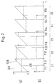
- the pulse width modulator is at the output of the pulse width modulator 40 Positioning deviation 400 can be tapped, the period according to FIG. 2 from a Pulse duration T11 to T15 and a pulse pause duration T21 to T25.
- Figure 2 are Time-course diagrams for selected signal courses are shown.
- Figure 2a is a normalized ramp signal 500 as a sawtooth signal between the limit values "-1" and "1" shown.
- FIG. 2a Positioning deviation 300 as a dashed line between the limit values "-1" and "1” normalized.
- Figure 2b is the pulse width modulated positioning deviation 400 during the states Z1 to Z5 corresponding to the positioning deviation 300 shown.
- the pulse width modulated positioning deviation 400 by normalizing the difference between pulse duration and pulse pause duration over the Sum of pulse duration and pulse pause duration during each state Z1 to Z5 Control voltage determined for the electric motor.
- the amount of the sum from pulse duration and pulse pause duration standardized difference between pulse duration and Pulse pause duration determines the traversing speed of the pen. Farther is made from the sign of the sum of the pulse duration and pulse pause duration standardized difference of pulse duration and pulse pause duration the direction of travel of the Pen determined.
- the positioning deviation 300 is zero.
- the Pulse duration T11 of the pulse width modulated positioning deviation 400 and the Pulse pause duration T21 comprise the same time duration in state Z1.
- the value of Positioning error 300 is zero, which means that the pen position is one exact mapping of the instantaneous measurement signal 100 is. A correction of the Pen position is therefore not required.
- the pulse duration T12 is a lot longer than the pulse pause duration T22 of the pulse width modulated positioning deviation 400 in state Z2.
- the large amount of the sum of the pulse duration T12 and Pulse pause duration T22 standardized time difference between the pulse duration T12 and the Pulse pause duration T22 causes the pen 10 to move at a high speed in a first direction of movement transverse to the transport direction of the Record carrier.
- the amount of the pen decreases the difference standardized by the sum of pulse duration T12 and pulse pause duration T22 between the pen position signal 200 and the measurement signal 100, so that the Positioning deviation 300, as shown in state Z3, becomes zero approximates.
- the pulse duration T13 is still longer than the pulse pause duration T23, however, the amount is the sum of the pulse duration T13 and the pulse pause duration T23 normalized difference between the pulse duration T13 and the pulse pause duration T23 in State Z3 is smaller than the difference from the sum of the pulse duration T13 and Pulse pause duration T23 standardized pulse duration T12 and the pulse pause duration T22 in Condition Z2.
- Pulse duration T13 and pulse pause duration T23 With increasing decrease in the amount of the total Pulse duration T13 and pulse pause duration T23 standardized difference from pulse duration T13 and Pulse pause duration T23 reduces the travel speed of the stylus 10 transversely to the direction of transport of the recording medium until reaching the Condition Z1.
- the positioning deviation 300 approaches the value Zero, so that, as shown in state Z5, the pulse duration T15 increases and the Pulse pause time T25 is reduced until state Z1 is reached.
- the amount of over the Sum of pulse duration T15 and pulse pause duration T25 standardized difference from the Pulse duration T15 and the pulse pause duration T25 is comparatively short, so that the Pen 10 is moved with low travel speed.
- the standardized difference based on the sum of pulse duration T15 and pulse pause duration T25 the pulse duration T15 and the pulse pause duration T25 negative, so that the pen 10 in the second direction of movement.
- the high positioning accuracy is achieved in particular by the fact that Pulse width modulation using a binary coded output signal continuous transmission spectrum is characterized in the range of values that Positioning deviation 300 an image of the Measurement signal 100 to the pen position is made possible.
- Pulse width modulation using a binary coded output signal continuous transmission spectrum is characterized in the range of values that Positioning deviation 300 an image of the Measurement signal 100 to the pen position is made possible.
- the capture range of the pulse width modulator 40 can be designed such that, on the one hand already in absolute terms, small absolute values, different from zero Positioning deviations 300 a large change in the duty cycle of the Pulse Width Modulated Positioning Deviation 400 causes a high internal Reinforcement corresponds and thus a precise positionability of the pen 10 corresponding to the measurement signal 100, and on the other hand limits of the capture range are dimensioned such that reaching a limit the maximum Movement speed of the pen 10 causes. Doing so is under catch area of the pulse width modulator 40 the value range of the positioning deviation 300 understood, which is transferable to a proportional duty cycle.
- the Positioning deviation 300 has the upper limit of the capture range pulse width modulated positioning deviation 400 permanently the logical state ONE
- the pen 10 at maximum travel speed in its first Movement direction are moved until the positioning deviation 300 the upper Falls below the limit of the catch range.
- Falls below the positioning deviation 300 has the lower limit of the capture range
- the Pen 10 with maximum travel speed in its second Movement direction is moved until the positioning deviation 300 the lower Limit of the catch range exceeds.
- the capture range of the pulse width modulator 40 is normalized in FIG. 2 by the limit values “1” and “-1” of the amplitude scale shown.
Landscapes
- Physics & Mathematics (AREA)
- General Physics & Mathematics (AREA)
- Recording Measured Values (AREA)
- Control Of Position Or Direction (AREA)
Description
Dieser bekannte Apparat ist mit dem Nachteil behaftet, daß die durch die Totbandeinrichtung vorbestimmte Bandbreite des Meßsignals sich als Aufzeichnungsfehler zwischen dem tatsächlichen Meßsignal und dem aufgezeichneten Signal bemerkbar macht. Änderungen des Meßsignals innerhalb der Bandbreite der Totbandeinrichtung werden nicht aufgezeichnet. Insoweit ist die Bandbreite der Totbandeinrichtung ein Maß für die Aufzeichnungsgenauigkeit beziehungsweise der Güteklasse der Aufzeichnungseinnchtung.
Eine vorteilhafte Ausgestaltung der Erfindung geht aus dem Patentanspruch 2 hervor.
- Figur 1
- ein Prinzipschaltbild für einen Positionierregelkreis
- Figur 2
- Zeitverlaufsdiagramme für ausgewählte Signalverläufe
Claims (2)
- Verfahren zum Positionieren eines Schreibstiftes (10) in einer Registriereinrichtung zum Aufzeichnen des Zeitverlaufes mindestens eines anschaltbaren Meßsignals (100), bei dem die aktuelle Schreibstiftposition bestimmt wird, das Meßsignal mit der aktuellen Schreibstiftposition verglichen wird, wobei eine Positionierabweichung (300) als Differenz aus dem Meßsignal und der aktuellen Schreibstiftposition bestimmt wird, und bei dem in Abhängigkeit von der Positionierabweichung der Schreibstift (10) entsprechend dem Meßsignal mit einem Elektromotor (90) nachgeführt wird, wobei der Nachführungskreis ein Mittel zur galvanisch getrennten Übertragung elektrischer Signale beinhaltet.
dadurch gekennzeichnet,daß die Positionierabweichung (300) pulsbreitenmoduliert wird,daß die pulsbreitenmodulierte Positionierabweichung (400) potentialfrei an einen Signalumformer (70) übertragen wird,daß mit dem Signalumformer (70) aus der pulsbreitenmoduliertenPositionierabweichung (400) durch Normierung der Differenz aus Pulsdauer (T11 bis T15) und Pulspausedauer (T21 bis T25) über die Summe aus Pulsdauer (T11 bis T15) und Pulspausedauer (T21 bis T25) eine Steuerspannung für den Elektromotor (90) bestimmt wird unddaß aus dem Vorzeichen der über die Summe aus Pulsdauer (T11 bis T15) und Pulspausedauer (T21 bis T25) normierten Differenz aus Pulsdauer (T11 bis T15) und Pulspausedauer (T21 bis T25) die Verfahrrichtung des Schreibstiftes (10) bestimmt wird. - Verfahren nach Anspruch 1
dadurch gekennzeichnet,
daß aus dem Betrag der über die Summe aus Pulsdauer (T11 bis T15) und Pulspausedauer (T21 bis T25) normierten Differenz aus Pulsdauer (T11 bis T15) und Pulspausedauer (T21 bis T25) die Verfahrgeschwindigkeit des Schreibstiftes (10)bestimmt wird.
Applications Claiming Priority (3)
| Application Number | Priority Date | Filing Date | Title |
|---|---|---|---|
| DE19541130 | 1995-10-27 | ||
| DE19541130A DE19541130A1 (de) | 1995-10-27 | 1995-10-27 | Verfahren zum Positionieren eines Schreibstiftes in einer Registriereinrichtung |
| US08/740,064 US5764244A (en) | 1995-10-27 | 1996-10-24 | Arrangement for positioning a pen in a recording device |
Publications (2)
| Publication Number | Publication Date |
|---|---|
| EP0770853A1 EP0770853A1 (de) | 1997-05-02 |
| EP0770853B1 true EP0770853B1 (de) | 1999-03-10 |
Family
ID=26020087
Family Applications (1)
| Application Number | Title | Priority Date | Filing Date |
|---|---|---|---|
| EP96250242A Expired - Lifetime EP0770853B1 (de) | 1995-10-27 | 1996-10-24 | Verfahren zum Positionieren eines Schreibstiftes in einer Registriereinrichtung |
Country Status (4)
| Country | Link |
|---|---|
| US (2) | US5764016A (de) |
| EP (1) | EP0770853B1 (de) |
| JP (1) | JPH09145423A (de) |
| DE (1) | DE19541130A1 (de) |
Families Citing this family (6)
| Publication number | Priority date | Publication date | Assignee | Title |
|---|---|---|---|---|
| US8903577B2 (en) | 2009-10-30 | 2014-12-02 | Lsi Industries, Inc. | Traction system for electrically powered vehicles |
| US8604709B2 (en) | 2007-07-31 | 2013-12-10 | Lsi Industries, Inc. | Methods and systems for controlling electrical power to DC loads |
| US7598683B1 (en) | 2007-07-31 | 2009-10-06 | Lsi Industries, Inc. | Control of light intensity using pulses of a fixed duration and frequency |
| JP5405439B2 (ja) * | 2010-11-10 | 2014-02-05 | 株式会社チノー | 記録計 |
| FR3007911B1 (fr) * | 2013-06-27 | 2015-06-26 | Somfy Sas | Dispositif de controle d’un moteur |
| JP6088464B2 (ja) * | 2014-05-29 | 2017-03-01 | ファナック株式会社 | アンプ一体型ロボット制御装置 |
Family Cites Families (10)
| Publication number | Priority date | Publication date | Assignee | Title |
|---|---|---|---|---|
| JPS6034052B2 (ja) * | 1979-10-04 | 1985-08-06 | グラフテック株式会社 | 記録計 |
| US4368411A (en) * | 1981-07-13 | 1983-01-11 | Kollmorgen Technologies Corporation | Control system for electric motor |
| US4423412A (en) * | 1981-09-30 | 1983-12-27 | The Foxboro Company | Industrial process indicating/recording apparatus using stepping motor drive |
| JPS62110117A (ja) * | 1985-11-08 | 1987-05-21 | Yokogawa Electric Corp | ペンレコ−ダ |
| US4888710A (en) * | 1987-12-11 | 1989-12-19 | Ametek, Inc. | Pen tip position detector |
| US4893066A (en) * | 1988-09-19 | 1990-01-09 | Hewlett-Packard Company | Hybrid sample rate servo motor controller |
| DE69114581T2 (de) * | 1990-06-27 | 1996-03-28 | Konishiroku Photo Ind | Vorrichtung zur Bilderzeugung. |
| JPH0667716A (ja) * | 1992-08-19 | 1994-03-11 | Mitsubishi Electric Corp | 数値制御装置並びに数値制御方法 |
| US5455609A (en) * | 1992-09-30 | 1995-10-03 | Hewlett-Packard Company | Printhead servicing station for printers |
| US5329217A (en) * | 1992-12-30 | 1994-07-12 | Allen-Bradley Company, Inc. | Compensated feedforward voltage for a PWM AC motor drive |
-
1995
- 1995-10-27 DE DE19541130A patent/DE19541130A1/de not_active Withdrawn
-
1996
- 1996-10-24 EP EP96250242A patent/EP0770853B1/de not_active Expired - Lifetime
- 1996-10-24 US US08/736,627 patent/US5764016A/en not_active Expired - Fee Related
- 1996-10-24 US US08/740,064 patent/US5764244A/en not_active Expired - Fee Related
- 1996-10-25 JP JP8301255A patent/JPH09145423A/ja active Pending
Also Published As
| Publication number | Publication date |
|---|---|
| US5764244A (en) | 1998-06-09 |
| EP0770853A1 (de) | 1997-05-02 |
| JPH09145423A (ja) | 1997-06-06 |
| DE19541130A1 (de) | 1997-04-30 |
| US5764016A (en) | 1998-06-09 |
Similar Documents
| Publication | Publication Date | Title |
|---|---|---|
| DE69119827T2 (de) | Steuerungsmethode der Zugriffsbewegungen mittels eines Magnetkopfes in einem harten Plattenantrieb | |
| EP0072022A1 (de) | Stromregelschaltung für einen von einer Leistungstreiberstufe gesteuerten Verbraucher | |
| DE19706756C2 (de) | Gradientenverstärker für einen Kernspintomographen und Kernspintomograph | |
| DE3819122C2 (de) | Verfahren und Vorrichtung zur Regelung der Position von Stellventilen | |
| DE2815906C2 (de) | ||
| DE3726885C2 (de) | Stellgerät | |
| DE19541130A1 (de) | Verfahren zum Positionieren eines Schreibstiftes in einer Registriereinrichtung | |
| EP1005147B1 (de) | Verfahren und Schaltungsanordnung zur Ermittlung einer optimalen Verstärkung des Integrators eines Drehzahlreglers | |
| DE4310859C2 (de) | Verfahren und Vorrichtung zur Positionierung einer Drosselklappe eines Kraftfahrzeuges | |
| DE4005255A1 (de) | Schaltungsanordnung zum betrieb eines stellgliedes | |
| EP0770852B1 (de) | Anordnung zum Positionieren eines Schreibstiftes in einer Registriereinrichtung | |
| DE2552369C2 (de) | Schaltungsanordnung zum Umwandeln eines analogen Signals in ein digitales, pulscodemoduliertes (PCM)-Signal | |
| DE3607249A1 (de) | Selbstabgleichender stiftschreiber | |
| DE2952311C2 (de) | Verfahren und Vorrichtung zum Umsetzen einer Meßspannung in einen digitalen Wert | |
| DE2460551C3 (de) | Steueranordnung für einen Schwingspulenmotor | |
| DE3505584A1 (de) | Fail-passive-treiberschaltung | |
| DE69009025T2 (de) | Bremssteuerung für Lokomotiven, insbesondere Rangierlokomotiven. | |
| DE3521594C2 (de) | ||
| DE2637175A1 (de) | Einrichtung zur erfassung von bestimmungsgroessen eines ebenen vektors | |
| DE2742079B2 (de) | Antriebsanordnung zur Positionierung einer Antriebswelle | |
| DE2833540A1 (de) | Einrichtung zum regeln der geschwindigkeit eines positionierers fuer die schreib-/lesekoepfe eines magnetplattenspeichers | |
| DE2345416A1 (de) | Verfahren und vorrichtung zur schlupffreien nachlaufsteuerung von schrittmotoren | |
| DE19518662B4 (de) | Vorrichtung zur Steuerung des Stromes durch eine Last nach Maßgabe eines Sollwertes | |
| DE69116367T2 (de) | Verfahren und Vorrichtung zur Impulserzeugung | |
| DE2751276C2 (de) |
Legal Events
| Date | Code | Title | Description |
|---|---|---|---|
| PUAI | Public reference made under article 153(3) epc to a published international application that has entered the european phase |
Free format text: ORIGINAL CODE: 0009012 |
|
| AK | Designated contracting states |
Kind code of ref document: A1 Designated state(s): CH DE FR GB IT LI NL |
|
| 17P | Request for examination filed |
Effective date: 19970424 |
|
| 17Q | First examination report despatched |
Effective date: 19970718 |
|
| GRAG | Despatch of communication of intention to grant |
Free format text: ORIGINAL CODE: EPIDOS AGRA |
|
| GRAG | Despatch of communication of intention to grant |
Free format text: ORIGINAL CODE: EPIDOS AGRA |
|
| GRAH | Despatch of communication of intention to grant a patent |
Free format text: ORIGINAL CODE: EPIDOS IGRA |
|
| RAP1 | Party data changed (applicant data changed or rights of an application transferred) |
Owner name: HARTMANN & BRAUN GMBH & CO. KG |
|
| GRAH | Despatch of communication of intention to grant a patent |
Free format text: ORIGINAL CODE: EPIDOS IGRA |
|
| GRAA | (expected) grant |
Free format text: ORIGINAL CODE: 0009210 |
|
| AK | Designated contracting states |
Kind code of ref document: B1 Designated state(s): CH DE FR GB IT LI NL |
|
| PG25 | Lapsed in a contracting state [announced via postgrant information from national office to epo] |
Ref country code: NL Free format text: LAPSE BECAUSE OF FAILURE TO SUBMIT A TRANSLATION OF THE DESCRIPTION OR TO PAY THE FEE WITHIN THE PRESCRIBED TIME-LIMIT Effective date: 19990310 Ref country code: IT Free format text: LAPSE BECAUSE OF FAILURE TO SUBMIT A TRANSLATION OF THE DESCRIPTION OR TO PAY THE FEE WITHIN THE PRESCRIBED TIME-LIMIT;WARNING: LAPSES OF ITALIAN PATENTS WITH EFFECTIVE DATE BEFORE 2007 MAY HAVE OCCURRED AT ANY TIME BEFORE 2007. THE CORRECT EFFECTIVE DATE MAY BE DIFFERENT FROM THE ONE RECORDED. Effective date: 19990310 |
|
| REG | Reference to a national code |
Ref country code: CH Ref legal event code: EP |
|
| ET | Fr: translation filed | ||
| GBT | Gb: translation of ep patent filed (gb section 77(6)(a)/1977) |
Effective date: 19990311 |
|
| REF | Corresponds to: |
Ref document number: 59601414 Country of ref document: DE Date of ref document: 19990415 |
|
| NLV1 | Nl: lapsed or annulled due to failure to fulfill the requirements of art. 29p and 29m of the patents act | ||
| PLBE | No opposition filed within time limit |
Free format text: ORIGINAL CODE: 0009261 |
|
| STAA | Information on the status of an ep patent application or granted ep patent |
Free format text: STATUS: NO OPPOSITION FILED WITHIN TIME LIMIT |
|
| 26N | No opposition filed | ||
| PG25 | Lapsed in a contracting state [announced via postgrant information from national office to epo] |
Ref country code: LI Free format text: LAPSE BECAUSE OF NON-PAYMENT OF DUE FEES Effective date: 20001031 Ref country code: CH Free format text: LAPSE BECAUSE OF NON-PAYMENT OF DUE FEES Effective date: 20001031 |
|
| REG | Reference to a national code |
Ref country code: CH Ref legal event code: PL |
|
| REG | Reference to a national code |
Ref country code: GB Ref legal event code: IF02 |
|
| PGFP | Annual fee paid to national office [announced via postgrant information from national office to epo] |
Ref country code: GB Payment date: 20030929 Year of fee payment: 8 |
|
| PGFP | Annual fee paid to national office [announced via postgrant information from national office to epo] |
Ref country code: FR Payment date: 20031009 Year of fee payment: 8 |
|
| PGFP | Annual fee paid to national office [announced via postgrant information from national office to epo] |
Ref country code: DE Payment date: 20031010 Year of fee payment: 8 |
|
| PG25 | Lapsed in a contracting state [announced via postgrant information from national office to epo] |
Ref country code: GB Free format text: LAPSE BECAUSE OF NON-PAYMENT OF DUE FEES Effective date: 20041024 |
|
| PG25 | Lapsed in a contracting state [announced via postgrant information from national office to epo] |
Ref country code: DE Free format text: LAPSE BECAUSE OF NON-PAYMENT OF DUE FEES Effective date: 20050503 |
|
| GBPC | Gb: european patent ceased through non-payment of renewal fee |
Effective date: 20041024 |
|
| PG25 | Lapsed in a contracting state [announced via postgrant information from national office to epo] |
Ref country code: FR Free format text: LAPSE BECAUSE OF NON-PAYMENT OF DUE FEES Effective date: 20050630 |
|
| REG | Reference to a national code |
Ref country code: FR Ref legal event code: ST |