EP0770798A2 - Kupplungseinheit eines automatischen, mechanischen Getriebes - Google Patents
Kupplungseinheit eines automatischen, mechanischen Getriebes Download PDFInfo
- Publication number
- EP0770798A2 EP0770798A2 EP96203716A EP96203716A EP0770798A2 EP 0770798 A2 EP0770798 A2 EP 0770798A2 EP 96203716 A EP96203716 A EP 96203716A EP 96203716 A EP96203716 A EP 96203716A EP 0770798 A2 EP0770798 A2 EP 0770798A2
- Authority
- EP
- European Patent Office
- Prior art keywords
- lubricant
- clutch
- rotational speed
- piston
- passageway
- Prior art date
- Legal status (The legal status is an assumption and is not a legal conclusion. Google has not performed a legal analysis and makes no representation as to the accuracy of the status listed.)
- Granted
Links
Images


Classifications
-
- F—MECHANICAL ENGINEERING; LIGHTING; HEATING; WEAPONS; BLASTING
- F16—ENGINEERING ELEMENTS AND UNITS; GENERAL MEASURES FOR PRODUCING AND MAINTAINING EFFECTIVE FUNCTIONING OF MACHINES OR INSTALLATIONS; THERMAL INSULATION IN GENERAL
- F16H—GEARING
- F16H57/00—General details of gearing
- F16H57/04—Features relating to lubrication or cooling or heating
-
- F—MECHANICAL ENGINEERING; LIGHTING; HEATING; WEAPONS; BLASTING
- F16—ENGINEERING ELEMENTS AND UNITS; GENERAL MEASURES FOR PRODUCING AND MAINTAINING EFFECTIVE FUNCTIONING OF MACHINES OR INSTALLATIONS; THERMAL INSULATION IN GENERAL
- F16H—GEARING
- F16H45/00—Combinations of fluid gearings for conveying rotary motion with couplings or clutches
- F16H45/02—Combinations of fluid gearings for conveying rotary motion with couplings or clutches with mechanical clutches for bridging a fluid gearing of the hydrokinetic type
-
- F—MECHANICAL ENGINEERING; LIGHTING; HEATING; WEAPONS; BLASTING
- F16—ENGINEERING ELEMENTS AND UNITS; GENERAL MEASURES FOR PRODUCING AND MAINTAINING EFFECTIVE FUNCTIONING OF MACHINES OR INSTALLATIONS; THERMAL INSULATION IN GENERAL
- F16D—COUPLINGS FOR TRANSMITTING ROTATION; CLUTCHES; BRAKES
- F16D25/00—Fluid-actuated clutches
- F16D25/06—Fluid-actuated clutches in which the fluid actuates a piston incorporated in, i.e. rotating with the clutch
- F16D25/062—Fluid-actuated clutches in which the fluid actuates a piston incorporated in, i.e. rotating with the clutch the clutch having friction surfaces
- F16D25/063—Fluid-actuated clutches in which the fluid actuates a piston incorporated in, i.e. rotating with the clutch the clutch having friction surfaces with clutch members exclusively moving axially
- F16D25/0635—Fluid-actuated clutches in which the fluid actuates a piston incorporated in, i.e. rotating with the clutch the clutch having friction surfaces with clutch members exclusively moving axially with flat friction surfaces, e.g. discs
- F16D25/0638—Fluid-actuated clutches in which the fluid actuates a piston incorporated in, i.e. rotating with the clutch the clutch having friction surfaces with clutch members exclusively moving axially with flat friction surfaces, e.g. discs with more than two discs, e.g. multiple lamellae
-
- F—MECHANICAL ENGINEERING; LIGHTING; HEATING; WEAPONS; BLASTING
- F16—ENGINEERING ELEMENTS AND UNITS; GENERAL MEASURES FOR PRODUCING AND MAINTAINING EFFECTIVE FUNCTIONING OF MACHINES OR INSTALLATIONS; THERMAL INSULATION IN GENERAL
- F16D—COUPLINGS FOR TRANSMITTING ROTATION; CLUTCHES; BRAKES
- F16D43/00—Automatic clutches
- F16D43/28—Automatic clutches actuated by fluid pressure
- F16D43/284—Automatic clutches actuated by fluid pressure controlled by angular speed
-
- F—MECHANICAL ENGINEERING; LIGHTING; HEATING; WEAPONS; BLASTING
- F16—ENGINEERING ELEMENTS AND UNITS; GENERAL MEASURES FOR PRODUCING AND MAINTAINING EFFECTIVE FUNCTIONING OF MACHINES OR INSTALLATIONS; THERMAL INSULATION IN GENERAL
- F16H—GEARING
- F16H45/00—Combinations of fluid gearings for conveying rotary motion with couplings or clutches
-
- F—MECHANICAL ENGINEERING; LIGHTING; HEATING; WEAPONS; BLASTING
- F16—ENGINEERING ELEMENTS AND UNITS; GENERAL MEASURES FOR PRODUCING AND MAINTAINING EFFECTIVE FUNCTIONING OF MACHINES OR INSTALLATIONS; THERMAL INSULATION IN GENERAL
- F16H—GEARING
- F16H61/00—Control functions within control units of change-speed- or reversing-gearings for conveying rotary motion ; Control of exclusively fluid gearing, friction gearing, gearings with endless flexible members or other particular types of gearing
- F16H61/14—Control of torque converter lock-up clutches
- F16H61/141—Control of torque converter lock-up clutches using means only actuated by centrifugal force
- F16H61/142—Control of torque converter lock-up clutches using means only actuated by centrifugal force the means being hydraulic valves
-
- F—MECHANICAL ENGINEERING; LIGHTING; HEATING; WEAPONS; BLASTING
- F16—ENGINEERING ELEMENTS AND UNITS; GENERAL MEASURES FOR PRODUCING AND MAINTAINING EFFECTIVE FUNCTIONING OF MACHINES OR INSTALLATIONS; THERMAL INSULATION IN GENERAL
- F16H—GEARING
- F16H45/00—Combinations of fluid gearings for conveying rotary motion with couplings or clutches
- F16H2045/005—Combinations of fluid gearings for conveying rotary motion with couplings or clutches comprising a clutch between fluid gearing and the mechanical gearing unit
-
- F—MECHANICAL ENGINEERING; LIGHTING; HEATING; WEAPONS; BLASTING
- F16—ENGINEERING ELEMENTS AND UNITS; GENERAL MEASURES FOR PRODUCING AND MAINTAINING EFFECTIVE FUNCTIONING OF MACHINES OR INSTALLATIONS; THERMAL INSULATION IN GENERAL
- F16H—GEARING
- F16H45/00—Combinations of fluid gearings for conveying rotary motion with couplings or clutches
- F16H45/02—Combinations of fluid gearings for conveying rotary motion with couplings or clutches with mechanical clutches for bridging a fluid gearing of the hydrokinetic type
- F16H2045/0273—Combinations of fluid gearings for conveying rotary motion with couplings or clutches with mechanical clutches for bridging a fluid gearing of the hydrokinetic type characterised by the type of the friction surface of the lock-up clutch
- F16H2045/0278—Combinations of fluid gearings for conveying rotary motion with couplings or clutches with mechanical clutches for bridging a fluid gearing of the hydrokinetic type characterised by the type of the friction surface of the lock-up clutch comprising only two co-acting friction surfaces
-
- F—MECHANICAL ENGINEERING; LIGHTING; HEATING; WEAPONS; BLASTING
- F16—ENGINEERING ELEMENTS AND UNITS; GENERAL MEASURES FOR PRODUCING AND MAINTAINING EFFECTIVE FUNCTIONING OF MACHINES OR INSTALLATIONS; THERMAL INSULATION IN GENERAL
- F16H—GEARING
- F16H45/00—Combinations of fluid gearings for conveying rotary motion with couplings or clutches
- F16H45/02—Combinations of fluid gearings for conveying rotary motion with couplings or clutches with mechanical clutches for bridging a fluid gearing of the hydrokinetic type
- F16H2045/0273—Combinations of fluid gearings for conveying rotary motion with couplings or clutches with mechanical clutches for bridging a fluid gearing of the hydrokinetic type characterised by the type of the friction surface of the lock-up clutch
- F16H2045/0284—Multiple disk type lock-up clutch
Definitions
- the present invention relates to automatic mechanical transmissions and, more particularly, to lock up type torque connector assemblies having a power interrupt clutch.
- the automatic mechanical transmission is made up of two main components, a torque converter assembly and a mechanical transmission.
- the torque converter assembly operatively connects the engine crankshaft to the mechanical transmission.
- the mechanical transmission has an output shaft connected to the vehicle drivetrain.
- the torque converter assembly includes a conventional torque converter, a lock-up clutch and an interrupt clutch.
- the lock-up clutch When the lock-up clutch is engaged, the torque converter is inoperative and power is transmitted directly through the torque converter assembly.
- the interrupt clutch is disengaged, the engine is decoupled from the mechanical transmission.
- the present invention relates to a piston return mechanism and a lubrication system for the interrupt clutch.
- the prior art transmission illustrated in the 4,860,861 patent utilizes a simple mechanism for reducing the flow of lubricant when the interrupt clutch is disengaged.
- a lubricant passageway formed in the driven clutch member provides a flow of pressurized lubricant to the clutch element.
- the piston spring blocks the lubricant passageway.
- lubricant flows through the passageway.
- An object of the present invention is to minimize clutch drag at engine idle speed when the clutch is disengaged, thereby minimizing idle fuel consumption.
- An object of the present invention is to provide a clutch assembly for automatic mechanical transmission which has lubricant provided to the clutch when the clutch is rotated at speeds above a first rotational speed. Thus, lubricant flow to the clutch is eliminated at speeds below the first rotational speed.
- Another object of the present invention is to provide a clutch lubrication system having three different lubrication levels.
- a "No Lubrication” level where at speeds below a first rotational speed, an "Intermediate Lubrication” level at speeds between a first and second rotational speed, and a "High Lubrication” level at speeds above a second rotational speed.
- a clutch assembly for use in an automatic mechanical transmission, which has a drive and driven clutch member rotatable about a common axis, and a clutch element interposed between the drive and driven members for connecting and disconnecting the members to interrupt the power transmission therebetween.
- the clutch element is actuated by a toroidal piston which cooperates with the drive member to form a toroidal fluid cavity biasing the piston axially in the direction of the clutch.
- a spring is provided for axially biasing the piston in the opposite direction to disengage the clutch element.
- a first internal lubrication passageway is formed in the drive member for feeding lubricant to the clutch element. The lubrication passageway is radially spaced from the axis of rotation and provided with an internal valve seat.
- a rotational speed sensitive first valve is oriented within the internal passageway for intermittently cooperating with the seat.
- the valve is biased against the seat at low speeds by lubricant pressure.
- centrifugal force biases the first valve off the valve seat providing lubricant to the clutch element.
- the present invention is defined in claim 1.
- a second lubrication passageway having an internal passageway spaced from the axis of rotation with a seat formed therein.
- a second rotational speed sensitive valve oriented in the second internal passageway is biased against the seat by lubricant pressure.
- the second valve is centrifugally biased off the seat opening the second passageway at speeds above a second rotational speed.
- the second speed is significantly higher than the first rotational speed, defining three lubrication states: a "no" lubricant state at speeds below the first speed; an "intermediate” lubrication state at speeds between the first and second speed; and a "high” lubrication state at speeds above the second rotational speed.
- a supplemental speed sensitive piston retract spring is provided to increase piston travel.
- the spring rate is selected such that when no activation pressure is provided to the piston, the supplemental spring further retracts the piston, decreasing clutch drag.
- the clutch actuation pressure is reduced to 0, there is sufficient centrifugal pressure to maintain the supplemental piston retract spring in the compressed state, thereby maintaining clutch responsiveness.
- Engine E is a source of power for a motor vehicle or the like.
- Engine E has a crankshaft 12 which is connected to input shroud 14 of torque converter assembly 16.
- Input shroud 14 is operatively connected to impeller 18 of torque converter 20.
- Input shroud 14 additionally cooperates with lock-up clutch 22 and hydraulic pump 24, as schematically illustrated.
- Interrupt clutch 30 includes a drive member 32 operatively connected to turbine 26 by web member 34.
- Drive member 32 cooperates with driven member 36, both of which rotate about a common axis.
- a clutch element is interposed between the drive and driven members for interrupting the transmission of power therebetween.
- the clutch element is comprised of two series of clutch plates, drive plates 38 which are connected to drive member 32 and driven plates 40 which are connected to driven member 36.
- a rotary hub 42 couples driven member 36 to transmission input shaft 28.
- the torque converter active mode in which its power is transmitted from the engine through the torque converter 20 to the transmission T
- the lock-up mode in which the power is transmitted directly through the torque converter assembly 16 while the torque converter is locked
- the interrupt mode in which the interrupt clutch is disengaged, disconnecting the engine crankshaft from transmission input shaft 28.
- the present invention focuses primarily upon minimizing the friction associated with interrupt clutch drag which occurs when the interrupt clutch is disengaged.
- FIG. 2 a detail cross-sectional side elevation of torque converter assembly 16 is shown.
- power is transmitted from input shroud 14 to impeller 18 of torque converter 20.
- Impeller 18 drives turbine 26, which is connected to drive member 32 by web member 34.
- interrupt clutch 30 is engaged, operatively locking drive and driven members 32 and 36.
- Interrupt clutch 30 is engaged when piston 52 is biased against the clutch drive and driven plates 38 and 40, preventing the relative rotation therebetween.
- Piston 52 is generally annular in shape, sealingly slidably cooperating with drive member 32 to define a toroidal variable displacement chamber 54 therebetween.
- Interrupt piston 52 is biased to the disengaged pistons by a pair of belleville washer stacks, primary piston spring 56 and supplemental piston spring 58.
- Primary piston spring 56 is relatively stronger, having sufficient load to urge the piston to a disengaged position at all normal engine operating speeds.
- Supplemental piston spring 58 is relatively weaker and is interposed between piston 52 and primary spring 56 to further cause the piston to retract relative to clutch plates 38 and 40.
- Drive member 32 has formed therein an input/output port 60 connected to the variable displacement chamber 54 at one end and having the other end connected to a hydraulic signal source which is radially spaced inboard of the variable displacement cavity. Due to the location of the hydraulic signal source radially inboard of the variable displacement cavity, the pressure within the variable displacement cavity will be equal to the hydraulic signal pressure plus a centrifugal pressure component which is a function of rotational speed of the drive member. As previously indicated, the primary spring 56 is sufficiently strong to cause the piston to retract at all normal operating speeds overcoming any typically encountered centrifugal pressure.
- the supplemental spring 58 is much weaker, however, the supplemental spring is strong enough to cause the piston to retract further at idle speeds to reduce interrupt clutch drag, thereby increasing the relative separation between the drive and driven plates at higher speeds.
- the centrifugal pressure within the variable displacement cavity will be sufficiently high to prevent the supplemental spring from further retracting the piston.
- the amount of supplemental piston movement will vary between maximum retract at or slightly above idle speed (approximately 400 rpm) to no additional piston movement at a selected higher speed with varying amount of supplemental movement at intermediate speeds therebetween.
- a high and low supplemental spring operating range of 400 to 800 rpm is preferred, but other ranges can be achieved according to the particular needs of the engine and transmission.
- the spring rate of the supplemental spring needs to be determined on an application to application basis dependent upon the radial location of the variable displacement chamber, the location of the hydraulic single input of the piston area and the amount of supplemental piston travel desired.
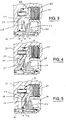
- the three states of the interrupt clutch piston are shown in Figures 3-5. In Figure 3, the piston is shown fully retracted by both the primary spring 56 and supplemental spring 58. There is a relatively large spacing between drive end driven clutch plates 38 and 40 and minimal volume in the variable displacement chamber 54.
- the drive member is rotating at a speed above 800 rpm.
- the centrifugal pressure component of the fluid within the variable displacement cavity is sufficient to excel the force of supplemental spring 58, thereby preventing any supplemental piston retraction beyond that achieved by the primary spring 56.
- the clutch plates are separated, however, the relative spacing therebetween is less than that shown in Figure 3.
- Lubricant flow is controlled by an internal lubricant passageway 62 which is formed in drive 32.
- the drive member 32 is made up of a splined drum 64 and a cover plate 66.
- Internal lubrication passageway 62 is formed in cover 66 as shown in greater detail in Figures 6-8 .
- Lubricant flows into the lubrication passageway from a lubrication chamber oriented between input shroud 14 and drive member 32.
- Lubrication passageway 62 has a large diameter section 68 and a small diameter section 70 with a frustoconical valve seat 72 formed therebetween.
- Ball 74 provides a rotational speed sensitive valve for sealingly cooperating with valve seat 72. Fluid pressure force F p provided by lubricant within the lubrication passageway 62 biases ball 74 sealingly against seat 72. As the drive member rotates, centrifugal force F c biases ball 74 radially outward. Depending upon the angle of the valve seat ⁇ , the inclination of the lubrication passageway axis ⁇ , the speed at which force F c overcomes force F p and reaction force F r can be varied.
- P s ⁇ 2 Sin ( ⁇ + ⁇ ) cos 3 ⁇ 2 D B R R ( W B - W 0 ) 3 G - W 0 ( R R 2 - R E 2 ) 2 G
- angle ⁇ is relatively small, e.g. between 0° and 10°.
- positive ⁇ angle causes the lubrication line to be inclined relative to the axis of rotation and in a direction which causes lubricant to flow radially inwardly, as illustrated in Figures 7 and 8.
- the preferred embodiment of the invention illustrated utilizes a series of lubrication passageways radially spaced about the axis of rotation which have at least two different valve opening speeds.
- four passageways provide passageways 62 and 62' which open at approximately 800 rpm and lubrication passageways 76 and 76' which open at approximately 1400 rpm.
- the only difference between lubrication passageways 62 and 76 is the angle of the seat ⁇ which is formed in the lubrication passageway.
- lubrication passageways 76 and 76' ⁇ is approximately 62°.
- Balls 74 are the same diameter and all four lubrication passageways and in each case a feral 78 is pressed into the lubrication passageway to prohibit the ball from escaping. It should be noted, however, that it would be possible to bias the ball against seat utilizing a spring, however a spring is unnecessary.
- the present design utilizes a simple machined seat angle to control operation, which works well repeatedly and cost effectively.
- the lubrication system illustrated in the preferred embodiment has three distinct lubrication states: a no lubricant flow state at speeds below a first rotational speed; an intermediate flow state where one pair of lubrication passageways are open at speeds above the first rotational speed but below a second rotational speed and a maximum lubricant flow state at speeds above the second rotational speed.
- the first rotational speed is between 600 and 1000 rpm and a second rotational speed is between 1000 and 1500 rpm.
- the conical valve seats in the lubrication passageways that open at the first rotational speed preferably have a half angle ⁇ of approximately 60° to 70°.
- valve seats of the second series of lubrication passageways which open at the higher second rotational speed having a conical half angle ⁇ which is approximately 3° to 5° less than that of the first valve seats.
- the lubrication passageways are inclined slightly at an angle relative to the axis of rotation, to cause the lubricant to flow radially inward and angle ⁇ which is less than 10°.
- ⁇ falls between 3° and 5°.
Landscapes
- Engineering & Computer Science (AREA)
- General Engineering & Computer Science (AREA)
- Mechanical Engineering (AREA)
- Physics & Mathematics (AREA)
- Fluid Mechanics (AREA)
- General Details Of Gearings (AREA)
- Hydraulic Clutches, Magnetic Clutches, Fluid Clutches, And Fluid Joints (AREA)
- Gear-Shifting Mechanisms (AREA)
- One-Way And Automatic Clutches, And Combinations Of Different Clutches (AREA)
- Control Of Motors That Do Not Use Commutators (AREA)
- Flanged Joints, Insulating Joints, And Other Joints (AREA)
- Mechanical Operated Clutches (AREA)
Applications Claiming Priority (3)
| Application Number | Priority Date | Filing Date | Title |
|---|---|---|---|
| US07/998,901 US5305863A (en) | 1992-12-30 | 1992-12-30 | Clutch assembly for an automatic mechanical transmission |
| US998901 | 1992-12-30 | ||
| EP93310549A EP0605234B1 (de) | 1992-12-30 | 1993-12-24 | Kupplungseinheit eines automatischen mechanischen Getriebes |
Related Parent Applications (2)
| Application Number | Title | Priority Date | Filing Date |
|---|---|---|---|
| EP93310549.6 Division | 1993-12-24 | ||
| EP93310549A Division EP0605234B1 (de) | 1992-12-30 | 1993-12-24 | Kupplungseinheit eines automatischen mechanischen Getriebes |
Publications (3)
| Publication Number | Publication Date |
|---|---|
| EP0770798A2 true EP0770798A2 (de) | 1997-05-02 |
| EP0770798A3 EP0770798A3 (de) | 1998-06-17 |
| EP0770798B1 EP0770798B1 (de) | 2000-03-15 |
Family
ID=25545650
Family Applications (2)
| Application Number | Title | Priority Date | Filing Date |
|---|---|---|---|
| EP93310549A Expired - Lifetime EP0605234B1 (de) | 1992-12-30 | 1993-12-24 | Kupplungseinheit eines automatischen mechanischen Getriebes |
| EP96203716A Expired - Lifetime EP0770798B1 (de) | 1992-12-30 | 1993-12-24 | Kupplungseinheit eines automatischen, mechanischen Getriebes |
Family Applications Before (1)
| Application Number | Title | Priority Date | Filing Date |
|---|---|---|---|
| EP93310549A Expired - Lifetime EP0605234B1 (de) | 1992-12-30 | 1993-12-24 | Kupplungseinheit eines automatischen mechanischen Getriebes |
Country Status (9)
| Country | Link |
|---|---|
| US (1) | US5305863A (de) |
| EP (2) | EP0605234B1 (de) |
| JP (1) | JP3531119B2 (de) |
| KR (1) | KR100254928B1 (de) |
| AT (2) | ATE163466T1 (de) |
| BR (1) | BR9305376A (de) |
| DE (2) | DE69328130T2 (de) |
| ES (2) | ES2144203T3 (de) |
| MX (1) | MX9400032A (de) |
Cited By (1)
| Publication number | Priority date | Publication date | Assignee | Title |
|---|---|---|---|---|
| EP1130287A1 (de) * | 2000-02-28 | 2001-09-05 | Isuzu Motors Limited | Antriebsvorrichtung für Fahrzeuge |
Families Citing this family (38)
| Publication number | Priority date | Publication date | Assignee | Title |
|---|---|---|---|---|
| JP3033381B2 (ja) * | 1993-03-08 | 2000-04-17 | 日産自動車株式会社 | 自動変速機の回転クラッチ |
| US5706694A (en) | 1996-08-19 | 1998-01-13 | Tesma International Inc. | Plate clutch assembly having a torque transmitting member with an improved lubrication controlling dam structure and method of making the same |
| US6244407B1 (en) | 1998-09-15 | 2001-06-12 | Borgwarner Inc. | Multi-disk friction device having forced lubrication on demand |
| JP3451960B2 (ja) * | 1998-09-22 | 2003-09-29 | アイシン・エィ・ダブリュ株式会社 | 自動変速機 |
| EP1302700B1 (de) * | 1998-11-13 | 2011-07-27 | Yutaka Giken Co., Ltd. | Antriebssystem für Kleinfahrzeug |
| US6227340B1 (en) | 1999-08-24 | 2001-05-08 | Borgwarner Inc. | Automatic transmission with dual gain multi-disk friction device |
| DE19957511A1 (de) | 1999-11-30 | 2001-06-21 | Borg Warner Automotive Gmbh | Lamelle für ein Kraftübertragungsaggregat, zum Beispiel für eine Schaltkupplung |
| US6543596B2 (en) | 2000-04-24 | 2003-04-08 | Borgwarner, Inc. | Multi-disk friction device having low-drag characteristics |
| US6634866B2 (en) | 2001-08-17 | 2003-10-21 | Borgwarner, Inc. | Method and apparatus for providing a hydraulic transmission pump assembly having a one way clutch |
| US6588559B2 (en) | 2001-09-18 | 2003-07-08 | Borgwarner, Inc. | Two-way clutch biasing assembly |
| US6554113B2 (en) | 2001-09-20 | 2003-04-29 | Borgwarner, Inc. | Torque limiting accessory drive assembly |
| DE50211959D1 (de) * | 2002-04-12 | 2008-05-08 | Borgwarner Inc | Torsionsschwingungsdämpfer sowie Versteifungselement für einen solchen |
| EP1371875B1 (de) * | 2002-06-15 | 2006-03-29 | BorgWarner Inc. | Vorrichtung zur Dämpfung von Drehschwingungen |
| DE10230183B4 (de) | 2002-07-05 | 2013-06-06 | Zf Friedrichshafen Ag | Verfahren zur Kühlfluidzuführung für Lamellenkupplungen und -bremsen in Automatgetrieben und Einrichtung zur Kühlfluidzuführung |
| DE10240679B4 (de) * | 2002-09-04 | 2004-08-05 | Audi Ag | Vorrichtung zum Betätigen einer Lamellenkupplung |
| DE10302016A1 (de) * | 2003-01-21 | 2004-07-29 | Zf Friedrichshafen Ag | Hydrauliksystem eines Getriebes mit einer Anfahrkupplung |
| US6868949B2 (en) | 2003-02-06 | 2005-03-22 | Borgwarner, Inc. | Start-up clutch assembly |
| US6854580B2 (en) | 2003-02-06 | 2005-02-15 | Borgwarner, Inc. | Torsional damper having variable bypass clutch with centrifugal release mechanism |
| DE502004002172D1 (de) * | 2004-04-10 | 2007-01-11 | Borgwarner Inc | Kupplungseinrichtung, insbesondere Anfahrkupplungseinrichtung |
| DE102004030660A1 (de) | 2004-06-24 | 2006-01-26 | Borgwarner Inc., Auburn Hills | Kupplung |
| DE502004006495D1 (de) * | 2004-06-29 | 2008-04-24 | Borgwarner Inc | Mehrfachkupplungsanordnung |
| JP2006214484A (ja) * | 2005-02-02 | 2006-08-17 | Nsk Warner Kk | 湿式多板クラッチ |
| JP2006322554A (ja) * | 2005-05-19 | 2006-11-30 | Nsk Warner Kk | 多板摩擦クラッチ装置 |
| JP4682810B2 (ja) * | 2005-11-07 | 2011-05-11 | マツダ株式会社 | 自動変速機の多板ブレーキ潤滑構造 |
| KR100789188B1 (ko) * | 2006-01-06 | 2008-02-25 | 한국파워트레인 주식회사 | 하이브리드 차량용 토크 컨버터 |
| CN101946105B (zh) * | 2008-03-04 | 2013-07-17 | 博格华纳公司 | 具有区域控制的离合器冷却回路的双离合器变速器 |
| WO2009128806A1 (en) * | 2008-04-18 | 2009-10-22 | Borgwarner Inc. | Dual clutch transmission having simplified controls |
| KR100953315B1 (ko) * | 2008-07-03 | 2010-04-20 | 현대자동차주식회사 | 차량용 자동 변속장치 |
| WO2010077560A2 (en) * | 2008-12-09 | 2010-07-08 | Borgwarner Inc. | Automatic transmission for a hybrid vehicle |
| US9086170B2 (en) | 2009-06-29 | 2015-07-21 | Borgwarner Inc. | Hydraulic valve for use in a control module of an automatic transmission |
| US8826760B2 (en) | 2009-12-31 | 2014-09-09 | Borgwarner Inc. | Automatic transmission having high pressure actuation and low pressure lube hydraulic circuit |
| US9989123B2 (en) | 2014-03-21 | 2018-06-05 | Eaton Cummins Automated Transmission Technologies Llc | Heavy duty transmission architecture |
| US9759302B2 (en) * | 2016-01-25 | 2017-09-12 | Ford Global Technologies, Llc | Bypass clutch for a torque converter |
| DE102016205190B4 (de) * | 2016-03-30 | 2025-06-26 | Aktiebolaget Skf | 1 - 17Vorgespannte Kupplungsausrücklagervorrichtung und Montageprozess einer derartigen Vorrichtung |
| GB2574263B (en) * | 2018-06-01 | 2020-09-30 | Caterpillar Sarl | Disconnect clutch |
| DE102018128771A1 (de) * | 2018-11-16 | 2020-05-20 | Schaeffler Technologies AG & Co. KG | Bremssystem, Achsträgereinheit für ein Fahrzeug, Fahrzeug mit einer derartigen Achsträgereinheit und Antriebseinheit |
| CN114658708B (zh) * | 2022-04-11 | 2024-07-02 | 华侨大学 | 一种负载转速双敏感抗流量饱和系统及其工程机械装置 |
| US12276332B1 (en) * | 2023-10-25 | 2025-04-15 | GM Global Technology Operations LLC | Torque transfer member having a strengthened fluid port and method of making the same |
Citations (1)
| Publication number | Priority date | Publication date | Assignee | Title |
|---|---|---|---|---|
| US4860861A (en) | 1987-09-17 | 1989-08-29 | Eaton Corporation | Torque converter lock-up and disconnect clutch structure |
Family Cites Families (18)
| Publication number | Priority date | Publication date | Assignee | Title |
|---|---|---|---|---|
| US1245718A (en) * | 1913-06-06 | 1917-11-06 | Herbert T Herr | Clutch. |
| US2740512A (en) * | 1952-01-25 | 1956-04-03 | Gen Motors Corp | Hydraulic clutch and relief valve therefor |
| US2907428A (en) * | 1953-10-12 | 1959-10-06 | Ford Motor Co | Clutch and controls therefor |
| US3176813A (en) * | 1962-08-30 | 1965-04-06 | Consolidation Coal Co | Centrifugally actuated fluid clutch |
| US3306408A (en) * | 1965-02-12 | 1967-02-28 | Deere & Co | Hydraulically engaged clutch with dual spring means and modulating valve |
| DE1906170B2 (de) * | 1969-02-07 | 1972-02-24 | Honda Giken Kogyo K K , Tokio | Hydrodynamischer drehmomentwandler mit einer ueberbrueckungs kupplung |
| US3667583A (en) * | 1970-04-22 | 1972-06-06 | Caterpillar Tractor Co | Self-modulated input clutch for vehicle drive transmissions |
| GB1273859A (en) * | 1970-09-22 | 1972-05-10 | Borg Warner Ltd | Fluid actuator |
| US4004417A (en) * | 1972-11-07 | 1977-01-25 | Caterpillar Tractor Co. | Torque converter with speed responsive slip clutch |
| DE2409515A1 (de) * | 1974-02-28 | 1975-09-11 | Daimler Benz Ag | Fliehkraftventil fuer schnell umlaufende arbeitsraeume |
| FR2398231A1 (fr) * | 1977-07-19 | 1979-02-16 | Saviem | Transmission a convertisseur hydrocinetique |
| US4784019A (en) * | 1985-04-03 | 1988-11-15 | Eaton Corporation | Torque converter disconnect and bypass clutch structure for automatic mechanical transmission |
| FR2583479B1 (fr) * | 1985-06-14 | 1990-01-12 | Valeo | Embrayage a circulation d'huile, notamment pour vehicule automobile |
| EP0247105B1 (de) * | 1985-11-26 | 1990-05-09 | J.M. Voith GmbH | Lamellenkupplung |
| US4905812A (en) * | 1989-01-26 | 1990-03-06 | J. I. Case Company | Apparatus for cooling a clutch assembly with a hydraulic fluid |
| US5136897A (en) * | 1991-05-09 | 1992-08-11 | Eaton Corporation | Smooth upshift control method/system |
| US5109721A (en) * | 1991-05-09 | 1992-05-05 | Eaton Corporation | Range shifting only fault tolerance method/system |
| JP5432085B2 (ja) | 2010-08-24 | 2014-03-05 | 三菱電機株式会社 | 電力半導体装置 |
-
1992
- 1992-12-30 US US07/998,901 patent/US5305863A/en not_active Expired - Lifetime
-
1993
- 1993-12-24 AT AT93310549T patent/ATE163466T1/de not_active IP Right Cessation
- 1993-12-24 DE DE69328130T patent/DE69328130T2/de not_active Expired - Fee Related
- 1993-12-24 EP EP93310549A patent/EP0605234B1/de not_active Expired - Lifetime
- 1993-12-24 DE DE69317106T patent/DE69317106T2/de not_active Expired - Fee Related
- 1993-12-24 AT AT96203716T patent/ATE190704T1/de not_active IP Right Cessation
- 1993-12-24 EP EP96203716A patent/EP0770798B1/de not_active Expired - Lifetime
- 1993-12-24 ES ES96203716T patent/ES2144203T3/es not_active Expired - Lifetime
- 1993-12-24 ES ES93310549T patent/ES2114595T3/es not_active Expired - Lifetime
- 1993-12-29 BR BR9305376A patent/BR9305376A/pt not_active IP Right Cessation
- 1993-12-30 KR KR1019930031226A patent/KR100254928B1/ko not_active Expired - Fee Related
- 1993-12-31 JP JP35173393A patent/JP3531119B2/ja not_active Expired - Fee Related
-
1994
- 1994-01-03 MX MX9400032A patent/MX9400032A/es unknown
Patent Citations (1)
| Publication number | Priority date | Publication date | Assignee | Title |
|---|---|---|---|---|
| US4860861A (en) | 1987-09-17 | 1989-08-29 | Eaton Corporation | Torque converter lock-up and disconnect clutch structure |
Cited By (1)
| Publication number | Priority date | Publication date | Assignee | Title |
|---|---|---|---|---|
| EP1130287A1 (de) * | 2000-02-28 | 2001-09-05 | Isuzu Motors Limited | Antriebsvorrichtung für Fahrzeuge |
Also Published As
| Publication number | Publication date |
|---|---|
| EP0770798A3 (de) | 1998-06-17 |
| ATE190704T1 (de) | 2000-04-15 |
| EP0770798B1 (de) | 2000-03-15 |
| DE69328130D1 (de) | 2000-04-20 |
| KR100254928B1 (ko) | 2000-08-01 |
| ES2114595T3 (es) | 1998-06-01 |
| KR940013932A (ko) | 1994-07-16 |
| EP0605234A1 (de) | 1994-07-06 |
| US5305863A (en) | 1994-04-26 |
| DE69317106D1 (de) | 1998-04-02 |
| BR9305376A (pt) | 1994-07-05 |
| EP0605234B1 (de) | 1998-02-25 |
| ES2144203T3 (es) | 2000-06-01 |
| JP3531119B2 (ja) | 2004-05-24 |
| DE69328130T2 (de) | 2000-11-16 |
| JPH06280902A (ja) | 1994-10-07 |
| MX9400032A (es) | 1994-07-29 |
| DE69317106T2 (de) | 1998-09-24 |
| ATE163466T1 (de) | 1998-03-15 |
Similar Documents
| Publication | Publication Date | Title |
|---|---|---|
| EP0770798B1 (de) | Kupplungseinheit eines automatischen, mechanischen Getriebes | |
| US4466311A (en) | Slip control system for a clutch | |
| EP1029183B1 (de) | Hydraulische maschine | |
| EP1079132B1 (de) | Automatisches Getriebe mit zweistufiger Reibungsvorrichtung | |
| EP0301590B1 (de) | Stufenloses Getriebe | |
| JPH05141441A (ja) | 変速機構 | |
| US4560043A (en) | Lockup torque converter having slip control means | |
| US4199047A (en) | Hydrokinetic torque converter with lock-up clutch | |
| US4462490A (en) | Control system for operation of fluid torque converter for vehicles | |
| EP0522022A1 (de) | Mehrmodenkupplung für schaltgetriebe | |
| US5054590A (en) | Control device and method for a pressure actuatable bridging coupling of a hydrodymanic torque converter | |
| US6318532B1 (en) | Externally controlled hydraulic torque transfer device | |
| US4760761A (en) | Control system for a direct-coupling mechanism in hydraulic power transmission means of a transmission for automotive vehicles | |
| US10808822B1 (en) | Hydrokinetic torque-coupling device having lock-up clutch with dual piston assembly and selectable one-way clutch | |
| EP0264380A1 (de) | Gerät zur verhinderung der motorabwürgung | |
| US4643046A (en) | Accessory drive device in engine | |
| EP0615080B1 (de) | Steuerungsventil für die Steuerung eines stufenlosen Getriebes | |
| GB2112880A (en) | Fluid torque converters employing one-way bridging clutch | |
| US4565267A (en) | Direct-coupling clutch control device for a torque converter in vehicular automatic transmission | |
| US4628767A (en) | Direct-coupled control for a torque converter including a two stage speed responsive valve control | |
| US3774400A (en) | Charging pressure control for fluid unit | |
| US4325270A (en) | Torque converter mechanism | |
| JPS6148024B2 (de) | ||
| US4378870A (en) | Vehicle torque converter | |
| US4181138A (en) | Governor valve assembly for automatic transmission units |
Legal Events
| Date | Code | Title | Description |
|---|---|---|---|
| PUAI | Public reference made under article 153(3) epc to a published international application that has entered the european phase |
Free format text: ORIGINAL CODE: 0009012 |
|
| AC | Divisional application: reference to earlier application |
Ref document number: 605234 Country of ref document: EP |
|
| AK | Designated contracting states |
Kind code of ref document: A2 Designated state(s): AT DE ES FR GB IT SE |
|
| RIN1 | Information on inventor provided before grant (corrected) |
Inventor name: STEURER, JOHN SCOTT Inventor name: WALING, LOYD ALAN Inventor name: GOOCH, DOUGLAS CRAIG |
|
| PUAL | Search report despatched |
Free format text: ORIGINAL CODE: 0009013 |
|
| AK | Designated contracting states |
Kind code of ref document: A3 Designated state(s): AT DE ES FR GB IT SE |
|
| 17P | Request for examination filed |
Effective date: 19981127 |
|
| GRAG | Despatch of communication of intention to grant |
Free format text: ORIGINAL CODE: EPIDOS AGRA |
|
| 17Q | First examination report despatched |
Effective date: 19990426 |
|
| GRAG | Despatch of communication of intention to grant |
Free format text: ORIGINAL CODE: EPIDOS AGRA |
|
| GRAG | Despatch of communication of intention to grant |
Free format text: ORIGINAL CODE: EPIDOS AGRA |
|
| GRAH | Despatch of communication of intention to grant a patent |
Free format text: ORIGINAL CODE: EPIDOS IGRA |
|
| GRAH | Despatch of communication of intention to grant a patent |
Free format text: ORIGINAL CODE: EPIDOS IGRA |
|
| GRAA | (expected) grant |
Free format text: ORIGINAL CODE: 0009210 |
|
| AC | Divisional application: reference to earlier application |
Ref document number: 605234 Country of ref document: EP |
|
| AK | Designated contracting states |
Kind code of ref document: B1 Designated state(s): AT DE ES FR GB IT SE |
|
| REF | Corresponds to: |
Ref document number: 190704 Country of ref document: AT Date of ref document: 20000415 Kind code of ref document: T |
|
| REF | Corresponds to: |
Ref document number: 69328130 Country of ref document: DE Date of ref document: 20000420 |
|
| ITF | It: translation for a ep patent filed | ||
| ET | Fr: translation filed | ||
| REG | Reference to a national code |
Ref country code: ES Ref legal event code: FG2A Ref document number: 2144203 Country of ref document: ES Kind code of ref document: T3 |
|
| PLBE | No opposition filed within time limit |
Free format text: ORIGINAL CODE: 0009261 |
|
| STAA | Information on the status of an ep patent application or granted ep patent |
Free format text: STATUS: NO OPPOSITION FILED WITHIN TIME LIMIT |
|
| 26N | No opposition filed | ||
| REG | Reference to a national code |
Ref country code: GB Ref legal event code: IF02 |
|
| PGFP | Annual fee paid to national office [announced via postgrant information from national office to epo] |
Ref country code: GB Payment date: 20051104 Year of fee payment: 13 Ref country code: AT Payment date: 20051104 Year of fee payment: 13 |
|
| PGFP | Annual fee paid to national office [announced via postgrant information from national office to epo] |
Ref country code: FR Payment date: 20051201 Year of fee payment: 13 |
|
| PGFP | Annual fee paid to national office [announced via postgrant information from national office to epo] |
Ref country code: SE Payment date: 20051202 Year of fee payment: 13 |
|
| PGFP | Annual fee paid to national office [announced via postgrant information from national office to epo] |
Ref country code: ES Payment date: 20051216 Year of fee payment: 13 |
|
| PGFP | Annual fee paid to national office [announced via postgrant information from national office to epo] |
Ref country code: DE Payment date: 20051230 Year of fee payment: 13 |
|
| PG25 | Lapsed in a contracting state [announced via postgrant information from national office to epo] |
Ref country code: SE Free format text: LAPSE BECAUSE OF NON-PAYMENT OF DUE FEES Effective date: 20061225 |
|
| PGFP | Annual fee paid to national office [announced via postgrant information from national office to epo] |
Ref country code: IT Payment date: 20061231 Year of fee payment: 14 |
|
| PG25 | Lapsed in a contracting state [announced via postgrant information from national office to epo] |
Ref country code: DE Free format text: LAPSE BECAUSE OF NON-PAYMENT OF DUE FEES Effective date: 20070703 |
|
| EUG | Se: european patent has lapsed | ||
| GBPC | Gb: european patent ceased through non-payment of renewal fee |
Effective date: 20061224 |
|
| REG | Reference to a national code |
Ref country code: FR Ref legal event code: ST Effective date: 20070831 |
|
| PG25 | Lapsed in a contracting state [announced via postgrant information from national office to epo] |
Ref country code: GB Free format text: LAPSE BECAUSE OF NON-PAYMENT OF DUE FEES Effective date: 20061224 Ref country code: AT Free format text: LAPSE BECAUSE OF NON-PAYMENT OF DUE FEES Effective date: 20061224 |
|
| REG | Reference to a national code |
Ref country code: ES Ref legal event code: FD2A Effective date: 20061226 |
|
| PG25 | Lapsed in a contracting state [announced via postgrant information from national office to epo] |
Ref country code: FR Free format text: LAPSE BECAUSE OF NON-PAYMENT OF DUE FEES Effective date: 20070102 Ref country code: ES Free format text: LAPSE BECAUSE OF NON-PAYMENT OF DUE FEES Effective date: 20061226 |
|
| PG25 | Lapsed in a contracting state [announced via postgrant information from national office to epo] |
Ref country code: IT Free format text: LAPSE BECAUSE OF NON-PAYMENT OF DUE FEES Effective date: 20071224 |