EP1029183B1 - Hydraulische maschine - Google Patents
Hydraulische maschine Download PDFInfo
- Publication number
- EP1029183B1 EP1029183B1 EP98957830A EP98957830A EP1029183B1 EP 1029183 B1 EP1029183 B1 EP 1029183B1 EP 98957830 A EP98957830 A EP 98957830A EP 98957830 A EP98957830 A EP 98957830A EP 1029183 B1 EP1029183 B1 EP 1029183B1
- Authority
- EP
- European Patent Office
- Prior art keywords
- pump
- motor
- torque
- displacement
- hydraulic
- Prior art date
- Legal status (The legal status is an assumption and is not a legal conclusion. Google has not performed a legal analysis and makes no representation as to the accuracy of the status listed.)
- Expired - Lifetime
Links
Images


Classifications
-
- F—MECHANICAL ENGINEERING; LIGHTING; HEATING; WEAPONS; BLASTING
- F16—ENGINEERING ELEMENTS AND UNITS; GENERAL MEASURES FOR PRODUCING AND MAINTAINING EFFECTIVE FUNCTIONING OF MACHINES OR INSTALLATIONS; THERMAL INSULATION IN GENERAL
- F16H—GEARING
- F16H61/00—Control functions within control units of change-speed- or reversing-gearings for conveying rotary motion ; Control of exclusively fluid gearing, friction gearing, gearings with endless flexible members or other particular types of gearing
- F16H61/38—Control of exclusively fluid gearing
- F16H61/40—Control of exclusively fluid gearing hydrostatic
- F16H61/42—Control of exclusively fluid gearing hydrostatic involving adjustment of a pump or motor with adjustable output or capacity
-
- F—MECHANICAL ENGINEERING; LIGHTING; HEATING; WEAPONS; BLASTING
- F16—ENGINEERING ELEMENTS AND UNITS; GENERAL MEASURES FOR PRODUCING AND MAINTAINING EFFECTIVE FUNCTIONING OF MACHINES OR INSTALLATIONS; THERMAL INSULATION IN GENERAL
- F16H—GEARING
- F16H47/00—Combinations of mechanical gearing with fluid clutches or fluid gearing
- F16H47/02—Combinations of mechanical gearing with fluid clutches or fluid gearing the fluid gearing being of the volumetric type
- F16H47/04—Combinations of mechanical gearing with fluid clutches or fluid gearing the fluid gearing being of the volumetric type the mechanical gearing being of the type with members having orbital motion
-
- F—MECHANICAL ENGINEERING; LIGHTING; HEATING; WEAPONS; BLASTING
- F16—ENGINEERING ELEMENTS AND UNITS; GENERAL MEASURES FOR PRODUCING AND MAINTAINING EFFECTIVE FUNCTIONING OF MACHINES OR INSTALLATIONS; THERMAL INSULATION IN GENERAL
- F16H—GEARING
- F16H37/00—Combinations of mechanical gearings, not provided for in groups F16H1/00 - F16H35/00
- F16H37/02—Combinations of mechanical gearings, not provided for in groups F16H1/00 - F16H35/00 comprising essentially only toothed or friction gearings
- F16H37/06—Combinations of mechanical gearings, not provided for in groups F16H1/00 - F16H35/00 comprising essentially only toothed or friction gearings with a plurality of driving or driven shafts; with arrangements for dividing torque between two or more intermediate shafts
- F16H37/08—Combinations of mechanical gearings, not provided for in groups F16H1/00 - F16H35/00 comprising essentially only toothed or friction gearings with a plurality of driving or driven shafts; with arrangements for dividing torque between two or more intermediate shafts with differential gearing
- F16H37/0833—Combinations of mechanical gearings, not provided for in groups F16H1/00 - F16H35/00 comprising essentially only toothed or friction gearings with a plurality of driving or driven shafts; with arrangements for dividing torque between two or more intermediate shafts with differential gearing with arrangements for dividing torque between two or more intermediate shafts, i.e. with two or more internal power paths
- F16H37/084—Combinations of mechanical gearings, not provided for in groups F16H1/00 - F16H35/00 comprising essentially only toothed or friction gearings with a plurality of driving or driven shafts; with arrangements for dividing torque between two or more intermediate shafts with differential gearing with arrangements for dividing torque between two or more intermediate shafts, i.e. with two or more internal power paths at least one power path being a continuously variable transmission, i.e. CVT
- F16H2037/0866—Power split variators with distributing differentials, with the output of the CVT connected or connectable to the output shaft
-
- F—MECHANICAL ENGINEERING; LIGHTING; HEATING; WEAPONS; BLASTING
- F16—ENGINEERING ELEMENTS AND UNITS; GENERAL MEASURES FOR PRODUCING AND MAINTAINING EFFECTIVE FUNCTIONING OF MACHINES OR INSTALLATIONS; THERMAL INSULATION IN GENERAL
- F16H—GEARING
- F16H2200/00—Transmissions for multiple ratios
- F16H2200/20—Transmissions using gears with orbital motion
- F16H2200/2002—Transmissions using gears with orbital motion characterised by the number of sets of orbital gears
- F16H2200/2007—Transmissions using gears with orbital motion characterised by the number of sets of orbital gears with two sets of orbital gears
Definitions
- This invention relates to hydromechanical transmissions, and more particularly to a hydromechanical transmission having rotating cylinder block hydrostatic units on each side of a grounded manifold and related through two planetary gear sets, and a simple clutch for selectively decoupling the pump from the input shaft, and to facilitate ease of external access to the fluid circuit without need of rotating fluid interfaces.
- Hydromechanical transmissions of many varieties have been conceived, although only a small number have actually been produced in commercial quantities. Many practical engineering problems must be addressed before a transmission would be considered acceptable for use in a production vehicle.
- One such problem is dynamic balancing of rotating components. In large machines with low input and output speeds, dynamic balancing is not a critical factor, but in modern passenger cars where the trend is toward higher engine speeds, dynamic balance becomes increasingly important since the unbalance forces are proportional to the square of the rotating velocity. Therefore, all serious engineering designs for such applications must provide for dynamic balance of rotating components, typically by some form of translating counterbalance mass. Complicating the issue, it may be difficult to design a system that is well balanced dynamically over its entire range of operating speeds. Thus, a hydromechanical transmission having components that are inherently dynamically balanced over their full range of operating speeds would be a significant improvement to the technology of hydromechanical transmissions.
- the speed and torque range of the transmission must be tailored precisely to the requirements of the driven application and the capabilities of the driver.
- modern passenger cars generally have an over-drive top gear with a ratio of approximately 0.7:1 and a low gear ratio of approximately 3:1 for a range spread of greater than 4:1.
- An ideal transmission would make it possible to cover this entire range without the need to shift gears, using hydraulic units large enough to develop the 3:1 low gear multiplication.
- the flow rate in conventional hydrostatic transmission is a source of fluid flow losses and noise.
- a hydromechanical transmission that greatly reduces the fluid flow rate compared to that in conventional hydrostatic CVTs would offer a significant advantage in efficiency and noise.
- the flow rate at neutral and at final ratio can be reduced to zero regardless of power throughput, and if the maximum flow is only 1/3 that of conventional hydrostatic transmissions of the same displacement, that improvement would be very welcome in the industry.
- a continuously variable transmission as defined in the preamble of claim 1 is known from US-A-3,132,534 .
- hydromechanical transmission range from large power plants on the order of railroad engines, marine engines and off road loaders and trucks, all the way down to snowmobiles, motorcycles, and even electric scooters.
- a high input shaft speed often needs to be geared down to produce a moderate pump speed at an elevated torque to better match the input speed to the pump characteristics.
- a clutch or brake mechanism that can be operated to smoothly decouple the input shaft from the pump would be a useful feature to reduce the start-up torque, eliminate lurching on start-up, and provide a soft "launch feel", that is, a smoothly operating, easily controlled acceleration from stand-still without lurching, jerking or lunging.
- an object of this invention to provide an improved hydromechanical transmission having an internal clutch mechanism for decoupling the input shaft from the pump to allow the transmission to free-wheel during start-up and other suitable times during operation of the vehicle.
- a continuously variable transmission as defined in independent claim 1, having an operating assembly including an input hydrostatic unit driven by an input shaft, and an output hydrostatic unit hydraulically related to the input hydrostatic unit through a stationary manifold between rotating cylinder blocks of the two units.
- the input and output hydrostatic units are mechanically related to each other and to the input shaft and an output shaft through at least one variable ratio or epicyclic gearset such as a planetary gearset or differential gearset, all enclosed within a housing.
- a stationary actuator fixed to the housing is linked to the hydrostatic units for adjusting their displacement, and that actuator is controlled by a control mechanism that causes the actuator to shift to positions that produce the desired transmission ratio.
- a brake is interposed between two elements in the gearset for selectively and smoothly decoupling and recoupling the input hydrostatic unit from the input shaft to allow the transmission to free-wheel when the brake is operated.
- Fig. 1 the invention is illustrated in a schematic diagram in its preferred embodiment as a serial, continuously variable, double planetary design. It is specifically intended for use in most bus, truck and automobile applications powered by diesel and gasoline internal combustion engines 40 where an overdrive final ratio is specified, although it would be useful in many other applications as well.
- the transmission is shown in Fig. 1 at hydraulic lock-up, with an input hydrostatic unit, or pump 50, at maximum displacement and the output hydrostatic unit, or motor 60, at zero displacement.
- the pump 50 has a non-rotating element and a rotating element driven by input torque delivered from an input shaft 65, and is effective to pressurize a working fluid such as hydraulic fluid.
- the motor 60 produces output torque delivered to an output shaft 76 when the motor is energized by the pressurized fluid from the pump 50.
- the two hydrostatic units can be simultaneously controlled from a master controller 100, or they can be independently controlled, as described in detail below.
- Rotary power from the engine 40 is delivered, typically directly from the engine crankshaft to a drive coupling 64 at the input end of the input shaft 65 of the transmission at the speed and torque of the engine 40, which can be operated at its optimum operating point for optimal efficiency and emissions.
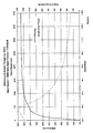
- the transmission has a continuously variable ratio that enables it to convert the rotary input power from the engine 40 to rotary output power to the vehicle drive shaft at any desired speed within a range from reverse, through zero, to an overdrive speed, for example 1.5 times engine speed, and at a corresponding torque, with an overall efficiency of about 90% or higher, as shown in Fig. 2.
- Input torque from the engine 40 is transmitted through the input shaft 65 to a planet carrier 67 of a motor planet gear set 70 having planet gears 72 mounted in the planet carrier 67 and engaged with an inner sun gear 73 and an outer ring gear 74.
- the input shaft 65 also drives a makeup pump 75 mounted in a front end closure of the transmission case.
- the ring gear 74 of the motor planet set 70 is connected drivingly to the motor 60 and to an output shaft 76.
- a torque tube 78 connects the sun gear 73 of the motor planet 70 set to a sun gear 83 of a pump planet set 80.
- the pump planet gear set has a pump planet carrier 77 in which are mounted pump planet gears 82 that are engaged with the inner pump sun gear 83 and an outer pump ring gear 84.
- the ring gear 84 of the pump planet set 80 is connected drivingly to the pump 50.
- the planet carrier 77 of the pump planet set 80 can be grounded to the transmission case via a releasable brake 85.
- the planet carrier 67 of the motor planet set 70 is spinning at input speed and therefore the sun gear 73 of the motor planet set 70 (and hence the sun gear 83 of the pump planet set 80) is rotating at 1+ (Rm/Sm) multiplied by the input speed, where Rm is the number of teeth in the motor set ring gear 74 and Sm is the number of teeth in the motor set sun gear 73.
- Rm is the number of teeth in the motor set ring gear 74
- Sm is the number of teeth in the motor set sun gear 73.
- the ring gear 84 of the pump planet set 80 (hence the pump 50) is driven to rotate at a speed equal to the speed of the sun gears 73 and 83 multiplied by (Sp/Rp) in the opposite direction, where Sp is the number of teeth on the pump set sun gear 83 and Rp is the number of teeth on the pump set ring gear.
- Sp is the number of teeth on the pump set sun gear 83
- Rp is the number of teeth on the pump set ring gear.
- the pump set sun gear 83 has 24 teeth and the pump set ring gear 84 has 64 teeth
- the pump set ring gear 84 and hence the pump will be rotating at sun gear speed multiplied by -(24/64), or 9/8 input speed in the opposite direction from input. Since the pump is at zero displacement, there is no pumping and therefore no reaction torque can be generated at the pump. Hence it rotates freely and the transmission output speed is zero.
- the brake 85 will be released before the engine is turned on, disengaging the pump planet carrier 77 of the pump planet set 80 from ground, so the planet carrier 77 can rotate freely. Therefore, no torque can be transmitted from the sun gear 83 to the pump 50. Without reaction torque transmitted back through the sun gears 83/73, no reaction torque can be transmitted from the input shaft 65 to the output shaft 76, even if the pump is at some displacement when the engine 40 is first turned on. The brake 85 will not be applied until the control has moved the pump to zero displacement, as verified via a sensor signal to the controller 100.
- the input torque is split into two parallel paths, as shown in Fig. 3.
- the first path is a direct mechanical path fed continually to the output shaft at the ratio of input torque multiplied by the inverse of 1 + the ratio of teeth on the motor set sun gear 73 and the motor set ring gear 74, or (1/(1+(Sm/Rm))).
- the second path is a mechanical path fed continually to the pump 50 at a torque equal to the input torque multiplied by the inverse of 1 + the product of the ratios of the numbers of teeth on the motor set ring gear 74 to the sun gear 73, and the numbers of teeth on the pump set ring gear 84 to the sun gear 83, or (1/(1+(Rm/Sm)) x Rp/Sp).
- the pump 50 With the brake 85 applied, grounding the pump gear set planet carrier 77 to the housing, the pump 50 is stroked from zero displacement to give a small displacement.
- the pump 50 is rotated by the input shaft 65, acting through the two planetary gear sets 70 and 80, at input speed multiplied by (1+ (Rm/Sm)) x (Sp/Rp) to begin pumping.
- Fluid displaced by the pump flows directly through flow channels 90 or 95 and drives the motor to produce output torque in the output shaft 76 for delivery through an output drive connection 96 on the output shaft 76 to a drive shaft of the vehicle. Since the pump 50 is at a small displacement, a small amount of torque to the pump 50 results in a high pressure and small flow rate, as shown in Fig. 4.
- Output torque input torque ⁇ 1 / 1 + Sm / Rm + 1 / 1 + Rm / Sm ⁇ Rp / Sp ⁇ motor displacement / pump displacement
- the pump speed approaches zero and motor speed approaches its maximum.
- the motor 60 reaches zero displacement, it can no longer accept fluid flow from the pump 50, so the pump 50 can no longer displace fluid and therefore stops rotating.
- the pump 50 now acts as a reaction unit for the sun gear 73 of the motor planet set 70.
- all the input torque now transfers through the motor planet set 70 to the output shaft 76. Due to the ratio of the sun gear 73 to the ring gear 74 of the motor planet set 70, the output speed increases and the output torque decreases (e.g.
- a brake could be applied to lock the pump 50 to ground. This will help in two ways: first it will stop the pump 50 from slipping due to hydraulic leakage, and second, it will reduce the hydraulic system pressure to makeup pressure, therefore reducing the load and hence windage loss of the motor.
- the pump brake could be actuated by makeup pressure or by electro-mechanical means.
- the transmission can drive the output shaft 76 in reverse.
- a double planetary system (a motor planet set and a pump planet set) in a hydromechanical transmission has numerous benefits over a single planet set, including the following:
- the transmission is controlled by means of the electronic control unit 100.
- the electronic control unit 100 receives several electronic signals from the engine, transmission and vehicle, as shown in Fig. 1.
- the electronic control unit 100 processes these signals using a computer algorithm, specific to each particular vehicle, to produce a control signal which it sends to a transmission ratio control unit 105 having electro-hydraulic devices, such as a servomotor or stepper motor 110 operating a pump modulation valve 115, and a control cylinder 116 by which the output ratio and speed of the transmission are controlled.
- This method of control offers great flexibility and enables the transmission to select the optimum ratio to achieve maximum system performance under a variety of operating conditions.
- the transmission behave in an adaptive, transparent manner, by reading many vehicle sensors such as applied brake force, steering angle, engine torque, rate of change of throttle position as well as throttle position etc. It is also possible to add manual features allowing the operator to select certain ratios.
- the electronic control unit 100 receives signals from the drive switch 118, throttle position sensor, input speed sensor 112, output speed sensor 114, and other sensors selected by the vehicle manufacturer, depending on the desired control sophistication. It processes these input signals and sends signals to the brake modulation valve 97 and the stepper motor 110 for controlling the pump modulation valve 115 by which the control valve 116 is operated to control the displacement of the pump 50 and the motor 60.
- a mechanical safety interlock may be incorporated into the drive switch 118 so that park, reverse and drive can only be selected when the vehicle is stopped or the brakes are applied, and the vehicle may only be started when the vehicle is in park, as in current automatic transmissions.
- the engine is started with the transmission in park.
- the controller 100 receives a signal from a contact in the drive selector switch 118 when the engine ignition switch is operated which signals the controller 100 to de-energize or release the brake 85, which allows the engine crankshaft to rotate without driving the pump 50.
- the electronic control unit 100 also sends a signal to the stepper motor 110 to send the transmission to the neutral position, just in case the vehicle was stopped with the transmission in a ratio other than neutral.
- the make up pump 75 produces enough pressure and flow to ensure that the hydraulic units 50 and 60 have stroked to their neutral position, and pressure is available to energize the hydraulic brake 85 by way of the brake modulation valve 97, and to sufficient lubrication pressure and flow or prevent damage to moving parts.
- Position sensors are attached to the non-rotating elements of the hydraulic units to generate signals that are transmitted to the electronic control unit 100 that the transmission is in neutral (i.e. pump at zero displacement, motor at maximum displacement), thus adding another level of control, safety, and reliability.
- the drive selector switch 118 is moved to the "drive" mode.
- the electronic control unit 100 signals the brake modulation valve 97 to gradually apply the hydraulic brake 85 while also signaling the stepper motor 110 of the transmission ration controller 105 to stroke the transmission to some forward ratio.
- the electronic control unit 100 can determine the required 'take off' characteristic of the vehicle, i.e. whether acceleration is to be slow and soft, hard and fast, or high torque (as in towing) from the rate of depression or force on the accelerator pedal and the load or resisting torque in the output shaft 76.
- the desired "take-off” is achieved by the rate of application of the brake 85 and the rate of change of the speed ratio produced by the stepper motor 110.
- the electronic control unit 100 signals the brake modulation valve 97 to apply full brake force and fully lock the pump planet carrier 77.
- the stepper motor 110 alone now controls all transmission ratios.
- the electronic control unit 100 can produce the required vehicle speed requested by the operator. By comparing these values to a preprogrammed operating schedule the electronic control unit 100 can vary the transmission ratio (via the stepper motor 110) to achieve the most effective driving regime. By comparing the input to output speed signals the electronic control unit 100 can determine the transmission ratio and make continual changes to the stepper motor 110 to achieve this regime. It is also possible to add a driving style switch, such as sport or economy mode, to enable the electronic control unit 100 to read different operating schedules and therefore give different driving conditions as requested by the operator, enabling the electronic control unit 100 to select the most efficient ratio for greatest economy, or achieving the highest performance for acceleration etc.
- a driving style switch such as sport or economy mode
- a small dump (short circuit) valve 117 may be inserted between the high-pressure and low-pressure lines 90 and 95 of the hydraulic units 50 and 60, allowing the hydraulic motor 60 to 'freewheel'.
- the dump valve 117 can be operated electronically and actuated by the electronic control unit 100 just before the neutral position is achieved.
- the dump valve 117 need only accept a small flow rate as the motor speed will be virtually zero at this point. Once the vehicle is stopped the electronic control unit 100 can close the dump valve 117 and return the transmission to its 'holding neutral' position.
- the electronic control unit 100 may be programmed to de-energize the brake modulation valve 97 therefore releasing the pump planet carrier 77. Although this is not necessary for the transmission to stay in the neutral mode, it readies the transmission for the next launch.
- the level of sophistication of control can be increased by using the variety of now common vehicle sensors, and more complex computer algorithms to achieve an adaptive transmission control, monitoring the driver's inputs and continually updating the operating schedules.
- the electronic control unit 100 can perform system diagnostic checks, by comparing the feedback signal from the servomotor or stepper motor 110 and actual ratio achieved and/or by measuring system and make up pressures and alerting the driver if these values fall beyond predetermined specifications.
- a low gear position is provided on the drive selector switch 118. This low gear mode can be activated either from a stationary start or on the fly from the drive mode. If low gear is selected from the park position, the transmission will start in the same manner as in drive mode, except that the transmission will not stroke beyond a predetermined ratio, staying at this lower maximum ratio if the throttle position is sufficiently depressed.
- the electronic control unit 100 will also use a different operating schedule to determine the transmission ratio, as starting in low gear will signify that a low speed, high torque demand is required, as in towing and maneuvering a heavy object. Also when driving in the low gear, due to the fact that a low ratio will be maintained, the driver will be offered more control from the throttle and more responsive engine braking at the expense of vehicle speed. This is particularly useful when towing heavy loads up and down hills.
- low gear operation will take effect only when the vehicle is moving slower than a predetermined speed. At that speed, the electronic control unit 100 will then change the transmission ratio smoothly and slowly to suit the different operating schedules. The transmission will then operate as indicated above. If the transmission is placed into drive mode from low gear, the electronic control unit 100 will change the transmission ratio smoothly and slowly to suit the new operating schedule.
- the electronic control unit 100 will assume that the vehicle needs to coast or be free-wheeled. To achieve this, the electronic control unit 100 will move the brake modulation valve 97 to release the brake 85 and disconnect engine power from the output shaft 76, and will stroke the transmission to full overdrive, (i.e. motor at zero displacement and pump at maximum displacement). This will enable the output shaft to rotate freely without any hydraulic pumping, causing the now released pump planet carrier 77 to rotate freely so that the vehicle can be externally maneuvered or towed.
- full overdrive i.e. motor at zero displacement and pump at maximum displacement
- a manual control may be used to move the servomotor or stepper motor 110 to the full overdrive position.
- Reverse mode can be selected with the engine 40 at idle and the foot brake applied.
- the electronic control unit 100 signals the brake modulation valve 97 to gradually apply the hydraulic brake 85 while also signaling the stepper motor 110 to stroke the transmission to some reverse ratio.
- the electronic control unit 100 will modulate the brake modulation valve 97 to give a smooth take off in reverse. There is only a limited amount of ratio available in reverse thereby limiting the speed in reverse to a safe and acceptable amount.
- the electronic control unit 100 will determine the reverse ratio from the throttle position and engine speed.
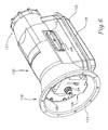
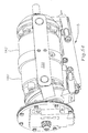
- FIG. 6-15 A preferred embodiment of the transmission shown schematically in Fig. 1 is shown in Figs. 6-15 as a serial, bent axis, double planetary, hydromechanical, continuously variable transmission.
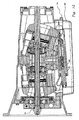
- This transmission has a housing 120, shown in Figs. 6, and 10-20, for enclosing an operating assembly, shown in Figs. 7-13.
- the housing 120 has an input end 119 from which protrudes the outer end 64 of the input shaft 65, and an input end peripheral flange 123 by which the transmission can be attached to the vehicle engine 40.
- the housing 120 also has an output end 121 from which protrudes the output end 96 of the output shaft 76.
- the housing 120 has a large opening 122 at the underside surrounded by a peripheral flange 124 to which a sump pan 125, shown in Figs. 6, 11-14 and 21-24, is attached by conventional removable fasteners (not shown) for easy access to the interior of the housing 120.
- a circular end closure 126 shown in Figs. 6 and 10-13, and shown in detail in Figs. 25-31, is fastened into a circular recess 127 in the input end opening of the housing 120 by machine screws 128. Holes 129 around the outside of the end closure 126 receive the screws 128 which are threaded into tapped holes in bosses 130 in the inside of the housing 120 spaced around the circular recess 127.
- the circular end closure 126 has a central opening 131 through which the end of the input shaft 65 extends, and a central cylindrical recess 132 for receiving the make-up pump 75.
- the make-up pump 75 can be any suitable type of pump for the application, such as a vane pump of known construction, having a pump rotor driven by the input shaft 65 in a pump housing 133, shown in Figs. 10-13 and Figs. 32-36.
- the brake 85 enables the pump 60 and downstream components of the operating assembly to be smoothly engaged and disengaged from the input shaft 65, as described above and in detail below.
- the operating assembly shown in Figs. 7-13 includes the input hydrostatic pump unit 50 and the output hydrostatic motor unit 60 hydraulically related to each other through the fluid passages 90 and 95, which extend straight through a stationary manifold block 140 between the pump 50 and the motor 60.
- the pump 50 and motor 60 are mechanically related through the first variable ration gear set such as an epicyclic planetary or differential gear set 70 and the second similar gear set 80.
- the stationary manifold block 140 shown in Figs. 7-15 and shown in detail in Figs. 37-42, is connected to the housing 120 through a pair of identical connector links 145, as shown in Figs. 10, 14 and 48.
- Each connector link 145 has a longitudinal stiffening rib 146 along its outside face, primarily to resist loads exerted on the link 145 by the yokes, discussed below.
- the links 145 are fastened by screws 148 into recesses 149, one in each side of the stationary manifold block 140, and project out through manifold 140 in the housing without unnecessary enlargement of the housing 120.
- an input yoke 151 and an output yoke 152 are each pivotally connected to the connector links 145 by swivel barrels 154 and 156 on the ends of yoke arms 158 and 160 on the input and output yokes 151 and 152.
- Both yokes 151 and 152 are identical to each other, so the description of one will suffice for both.
- the swivel barrels 154 and 156 are mounted for swiveling about two horizontal axes 170 and 172, shown in Fig. 10, on longitudinally spaced integral stub shafts 162 and 164 that project inwardly from the connector links 145.
- the two sets of stub shafts 162 and 164 are aligned on the axes 170 and 172, shown in Fig. 10, that intersect the main longitudinal axis 174 of the machine at the center of curvature of two convex spherical bearings 176 and 178 on which annular pump and motor cylinder blocks 180 and 182 are guided, as described below.
- the main longitudinal axis 174 of the machine coincides with the axis of the input shaft 65 and the coaxial output shaft 76.
- Each yoke 151 and 152 has a mounting flat 183 on its lower surface to which is attached a control clevis 184 and 186, respectively, each having a pair of spaced-apart depending arms.
- Control links 188 and 190 seen in Figs. 7- 9, are pinned between the lower ends of the control clevis arms and a control actuator 192, shown in detail in Figs. 8, 9, 11-13 and 49.
- the actuator 192 includes an actuator cylinder block 189, shown in detail in Figs. 50-53, which is fastened to the underside of the stationary manifold block 140, as shown in Figs. 8 and 9, so it is stationary relative to the manifold block 149 and the housing 120.
- the control links 188 and 190 are pinned to the ends of bars 191 and 193 mounted on the outer ends of two control pistons 194 and 196 and held thereon by nuts 197.
- the control pistons move in the cylinder 195 in the cylinder block 189 under the influence of hydraulic fluid controlled by a spool 198 connected to a rod 199 moved by the servomotor or stepper motor 110 to control the tilt angle of the yokes 151 and 152, as discussed below.
- the stationary nature of the actuator 192 makes control of the control yokes 151 and 152 simple, consistent and reliable.
- the stationary nature of the stationary manifold block 140 also affords access into the fluid circuit for simple and 152 simple, consistent and reliable.
- the stationary nature of the stationary manifold block 140 also affords access into the fluid circuit for simple connection of make-up fluid flow lines by way of a tapped port 201. External taps into the pressure channels for regenerative braking/acceleration and hydraulic power take-off are also made possible without the use of rotating interfaces or the like by the stationary manifold block 140.
- the make-up pump housing 133 shown in Figs. 32-36, has a cylindrical recess 202 in which a rotor 204 and vanes 205 of the make-up pump 75 are mounted and driven by the input shaft 65, as shown in Figs. 10-13, for pressurizing fluid drawn from the sump pan 125 to recharge the fluid circuit with fluid lost through leakage, and to pressurize the actuator 92.
- the hydraulic fluid from the make-up pump also is use to lubricate the bearings and sliding interfaces in the transmission.
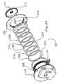
- the annular pump and motor cylinder blocks 180 and 182 of the input and output hydrostatic units 50 and 60 each include a ring of cylinders 206 and 208 in which hollow pump and motor pistons 210 and 212, respectively, are disposed, as shown in Figs 11-13. All the pistons 210 and 212 are identical, so a description of one will suffice for all.
- Each piston as best seen in Fig. 46, has a spherical head 214 and a cylindrical base 216 connected by a cylindrical shank 215. The cylindrical base 216 tapers toward the head 214 from a pair of annular grooves 218 and 220 in the base for receiving piston rings (not shown).
- An axial bore 222 extends completely through each piston 210 and 212 for conveying fluid from the cylinders in the cylinder block on one side of the manifold block, through the fluid passages 90 and 95 in the manifold block, through the pistons on the other side of the manifold block and into the cylinders in the other cylinder block.
- the spherical heads of the pistons 210 and 212 are seated in spherical sockets 224 in a pump torque ring 226 and a motor torque ring 228, each having a flat face in contact with the manifold block 140.
- the only two rotating fluid transfer interfaces in the transmission are the interfaces between the two sides of the manifold block 140 and the two torque rings 226 and 228. No torque is transmitted through these interfaces so distortion under torque load is minimal, thereby reducing leakage which otherwise could be caused by distortion of the torque ring face under load.
- the torque rings 226 and 228 are supported for rotation on a ring of caged needle bearings 230 surrounding a bearing support annulus 232 fastened to the center of the manifold block 140 by screws 234, one on each side of the manifold block.
- the piston heads 214 are held in the sockets 224 of the torque rings 226 and 228 by retainer rings 238 which are integral with the ring gears 84 and 74.
- the retainer rings 238 are fastened to the torque rings 226 and 228 by fasteners 240 which also provide a torque path between the ring gears 84 and 74 and the torque rings 226 and 228.
- the outer ends of the cylinders 206 and 208 are closed by floating pucks 236 best seen in Fig. 46.
- the pucks 236 each have a seal groove 237 for receiving a seal ring (not shown) and a spring groove 239 for receiving an annular wave spring which biases the puck outward against flat annular bearing surfaces 242 and 244 on the inner faces of the yokes 151 and 152, as shown in Fig. 47 for the yoke 152.
- the floating puck can move slightly axially and tilt slightly to follow a momentary perturbation or deviation from flatness of the yoke inner bearing surfaces 242 and 244.
- each puck 236 provides a hydrostatic bearing which just reacts the fluid force inside the cylinders 206 and 208 to minimize wear of the pucks and the bearing surfaces 242 and 244 of the yokes 151 and 152.
- An axial biasing force is exerted to urge the cylinder blocks 180 and 182 against That axial force is exerted by a set of wave springs 246 compressed between a snap ring (not shown) fitted into grooves 247 in the fluted axial bore 209 of the pump and motor cylinder blocks 180 and 182, and against a spherical ring 248 and 250 which is guided for tilting on the spherical bearings 176 and 178 about the centers of curvature of the spherical interfaces of the spherical rings and spherical bearings.
- the spherical rings 248 and 250 guide the pump and motor cylinder blocks 180 and 182 on the spherical bearings 176 and 178 for rotation and tilting about their respective centers of mass.
- Those centers of curvature coincide with the intersection of the axes 170 and 172 through the stub shafts 162 and 164, and the longitudinal axis 174 of the machine, as shown in Fig. 10, so that the axes of rotation of the cylinder blocks always intersects the tilting axis of the yokes 151 and 152 and the cylinder blocks always rotate about their centers of mass to ensure dynamic balance of the rotating elements.
- the axial force exerted by the two sets of wave springs 246 is transmitted through the spherical rings 248 and 250 to the spherical bearings 176 and 178, and thence (on the pump side) to a pump preload flange 252, shown most clearly in Figs. 46 and 46A.
- the radial outer surface of the pump preload flange 252 is splined at 253 and engaged with splines 254 in the bore of the ring gear 84.
- the splines 254 are shallower than the teeth of the ring gear 84, so the preload flange 252 can slide into the ring gear 84 only about one quarter of the way until it is engaged by the higher teeth of the ring gear 84.
- This engagement enables the axial force exerted on the preload flange 252 by the spherical bearing 176 to be transmitted to the ring gear 84 and its integral retainer ring 238 and thence to the torque ring 226 for ensuring contact of the torque ring 226 against the manifold block during start-up so that the fluid system remains sealed and make-up pump pressure can be developed by the make-up pump 75 for lubrication flow and charging the system during start-up.
- a stator tube 260 for coupling the pump planet carrier 77 to the brake 85 includes an externally splined inner end 262 engaged with an internally splined tubular extension 264 on the pump planet carrier 77.
- the stator tube 260 surrounds the input shaft 65 and extends from the planet carrier 77 to an outer splined end 266 engaged with an internally splined ferrule 268 projecting inwardly from a brake flange 270.
- the brake flange 270 has an outer peripheral cylindrical flange 272 that is castellated or toothed on its outer radially facing surface to receive inwardly projecting radial teeth 274 of three clutch discs 276.
- the brake flange 270 and the clutch discs 276 lie concentrically within a brake ring 278 having an outer radial flange 280 that is fastened to the circular end closure 126 and has an axial cylindrical section 282 concentrically surrounding the cylindrical flange 272.
- the interior of the axial cylindrical section 282 is grooved or slotted to receive teeth 284 projecting radially outward from the outer end of a plurality of annular clutch plates 286 bracketing the clutch discs 276.
- a radial lip at the end of the axial cylindrical section 282 prevents the clutch discs 276 and plates 286 from being pushed out of the end of the axial cylindrical section 282.
- An annular brake piston 288 is seated in the annular cylinder 134 and is movable axially under influence of fluid admitted in the annular cylinder 134 behind the brake piston 288 to exert a precisely controlled axial force on the clutch plates 286 and the clutch discs 276 to transmit torque from the brake flange 270 to the brake ring 278 and thence to the housing.
- the fluid pressure released into the annular cylinder 134 for acting against the brake piston 288 is controlled by the brake modulation valve 97, which is a commercially available pulse modulated solenoid controlled fluid valve. In this way, the reaction torque transmitted from the pump planet carrier to ground, and hence the torque transmitted to the pump 50, is precisely controlled by the controller 100 through the brake modulation valve 97.
- the brake 85 In operation, when the starter of the vehicle engine is energized, the brake 85 is released to allow the planet carrier 77 to spin freely, preventing torque from being transmitted to the pump.
- the starter motor has a much lighter load without having to rotate the pump and there is no chance that the vehicle could surge forward or backward because of an inadvertent adjustment of the pump displacement.
- the rotating input shaft 65 rotates the make-up pump 75 and fluid pressure at make-up pressure is developed in the system.
- Pressurized fluid flows from the make-up pump 75 through a radial hole 280 in the input shaft 65 and through an axial hole 282 and then out through another radial hole 284 into an annular space 286 between the input shaft 65 and the stator tube 260.
- the fluid flows along the annular space 286 and lubricates a needle bearing between the planet carrier 77 and the sun gear 83, shown in Fig. 46.
- the fluid continues flowing along the annular space 286 and squirts up through a hole 290 to be deflected by an oil deflector 292 into an axial hole in a pinion shaft 294 on which the pump planet gears 82 are mounted for rotation on needle bearings 296.
- Those needle bearings 296 are lubricated by hydraulic fluid flowing from the axial holes and out radial holes in the pinion shaft 294.
- the motor planet gears are likewise lubricated by fluid flowing through radial and axial holes in the end of the input shaft 65 and into similar fluid flow passages in and around the bearings and gears inside the motor 60 as illustrated in Figs. 10-13.
- the control unit 100 sends a signal to the servomotor or stepper motor 110, mounted on a bracket 298 to move the control rod 199 and the spool valve 198 threaded onto the rod 199 to a zero displacement position from which forward or reverse acceleration can be commenced.
- the driver selects forward or reverse on the drive selector switch 118 and depresses the accelerator.
- the controller 100 senses the rate and extent of depression of the accelerator and adjusts the transmission accordingly by sending a signal to the stepper motor 110 to move the control rod and spool valve to a new position at the desire speed, while also adjusting the throttle to increase the engine speed to some designated speed of operation, preferably at a rate of increase and to an operating speed that will result in optimal efficiency and minimal emissions.
- the position of the spool valve 198 controls the position of a follower spool sleeve 200 which in turn controls the position of the pump control piston 194, using system pressure delivered to a larger cross-sectional area behind the step 299 in the piston 194. Both pump control piston and motor control piston 196 are biased toward the left in Figs.
- the control rod 199 is pulled further to the right in Figs. 11-13 and 49 to cause the pump control piston 194 to move to the right correspondingly.
- the pump control piston will engage the end of the motor control piston 196 and the two control pistons 194 and 196 will move together toward the right through the continuously varying transmission ratio to the final ratio at hydraulic lock-up at which the motor is at zero displacement and the pump is at some large displacement.
- the advantage of the swashplate design is that the housing can be made smaller because the excursion of the tilting swashplates is less that the corresponding excursion of the tilting yokes 151 and 152 and their cylinder blocks.
- the disadvantage of the swashplate design is that it tends to wear faster because of the lateral forces exerted by the pistons in the cylinders. The resulting frictional forces also result in somewhat higher internal losses, so swashplate hydrostatic units have a bit lower efficiency that the bent axis units used in the embodiment of Figs. 6-15.
Claims (16)
- Stufenloses Getriebe, umfassend :zwei Hydraulikeinheiten, einschließlich einer Pumpe (50) und eines Motors (60), wobei jede ein Rotationselement (180, 182) und ein geerdetes Reaktionselement (151, 152) aufweist, wobei mindestens eine der Hydraulikeinheiten (50) im Hubvolumen verstellbar ist ;ein Steuersystem (100) zur Steuerung des Hubvolumens der einen Hydraulikeinheit ;einen regelbaren Motorgetriebesatz (70) mit ersten, zweiten und dritten miteinander kämmenden Getriebeelementen (72, 74, 73), und einen regelbaren Pumpengetriebesatz (80) mit ersten, zweiten und dritten miteinander kämmenden Getriebeelementen (82, 84, 83) ;eine Antriebswelle (65), die mit dem ersten Getriebeelement (72) des Motorgetriebesatzes (70) verbunden ist ;eine Abtriebswelle (76), die mit dem zweiten Getriebeelement (74) des Motorgetriebesatzes und mit dem Rotationselement (182) der zweiten Hydraulikeinheit (60) verbunden ist ;wobei das dritte Getriebeelement (73) des Motorgetriebesatzes (70) mit dem dritten Getriebeelement (83) des Pumpengetriebesatzes (80) verbunden ist ;wobei das zweite Getriebeelement des Pumpengetriebesatzes mit dem Rotationselement der ersten Hydraulikeinheit verbunden ist ;wobei die zwei Hydraulikeinheiten hydraulisch so verbunden sind, dass das verdrängte Fluid aus der ersten Hydraulikeinheit zu der zweiten Hydraulikeinheit fließt und umgekehrt ;gekennzeichnet durch eine Bremse (85), die das erste Element (82) des Pumpengetriebesatzes (80) lösbar an Masse anschließt ;
wodurch an die Antriebswelle (65) angelegtes Eingangsdrehmoment durch diese hindurch zu der Pumpe (50) übertragen wird, wenn die Bremse (85) im Eingriff ist, mittels des ersten und des dritten Elements (72, 73) des regelbaren Motorgetriebesatzes (70) und von dort mittels des dritten, ersten und zweiten Elements (82, 84, 83) des regelbaren Pumpengetriebesatzes (80), wobei es durch die im Eingriff befindliche Bremse (85) mit Masse reagiert, um die Pumpe (50) zu rotieren und ein Arbeitsfluid in der Pumpe druckzubeaufschlagen ; wobei das Übertragen des Eingangsdrehmoments von der Antriebswelle (65) auf die Pumpe (50) ein Reaktionsdrehmoment erzeugt, das durch das zweite Element (74) des regelbaren Motorgetriebesatzes (70) auf die Abtriebswelle (76) übertragen wird, wobei das druckbeaufschlagte Fluid durch eine Öffnung in einem Verteilerblock (140) zwischen den Hydraulikeinheiten zu dem Motor (60) befördert wird und den Motor (60) mit Energie versorgt, um Motordrehmoment zu produzieren, das zusätzlich zu dem Reaktionsdrehmoment als Ausgangsdrehmoment in der Abtriebswelle (76) auf die Abtriebswelle (76) übertragen wird. - Stufenloses Getriebe, wie in Anspruch 1 definiert, wobei :die Hydraulikeinheiten (50, 60) und die zwei verstellbaren Getriebesätze (70, 80) so konfiguriert sind, dass sie ein gewünschtes Endverhältnis ergeben und dass das Eingangsdrehmoment in einen ersten und einen zweiten parallelen Pfad aufgetrennt wird, wobei der erste parallele Pfad ein direkter mechanischer Pfad zu der Abtriebswelle (76) ist und der zweite parallele Pfad durch die erste und die zweite Hydraulikeinheit (50, 60) verläuft ;wobei die zweite Hydraulikeinheit (60) und die erste Hydraulikeinheit (50) ein Hubvolumenverhältnis haben, das das Drehmoment durch den zweiten parallelen Pfad multipliziert, wodurch zu dem durch den ersten parallelen Pfad übertragenen Drehmoment hinzuaddiert wird ;wodurch das Einstellen des Motorhubvolumens auf Null die Drehmomentmultiplikation von den Hydraulikeinheiten (50, 60) auf Null reduziert, sodass sie nur auf Reaktionsdrehmoment von dem mechanischen Drehmoment des ersten parallelen Pfads wirken und somit das gesamte Eingangsdrehmoment bzw. -energie direkt durch den Motorgetriebesatz (70) zu der Abtriebswelle (76) läuft, und Betätigen des Motors (60) auf maximales Hubvolumen und der Pumpe (50) auf null Hubvolumen das Getriebe in eine "Neutral halten"-Einstellung zum Halten eines Fahrzeugs in einer stationären Position bringt, wobei der Motor (60) und daher die Abtriebswelle (76) nicht in gleich welche Richtung rotieren können, da die Pumpe (60) keinerlei von dem Motor (60) abgeführtes Fluid aufnehmen kann.
- Stufenloses Getriebe, wie in Anspruch 2 definiert, wobei :das Betätigen der im Hubvolumen verstellbaren Pumpe (50) in einer der beiden Richtungen aus ihrer Null-Hubvolumenposition heraus die Richtung des Fluidflusses von der Pumpe (50) zu dem Motor (60) verändert und den Motor (60) und daher die Abtriebswelle (76) entweder in Vorwärts- oder Rückwärtsrichtung antreibt ;wodurch das Getriebe das Drehmoment sowohl im Vorwärts- als auch Rückwärtsrichtung hydraulisch multipliziert, ohne den Gang verändern zu müssen, wie folgt :wobei A = 1/(1+(Rm/Sm)) x Rp/Sp x Motorhubvolumen/Pumpenhubvolumen.


- Stufenloses Getriebe, wie in Anspruch 1 definiert, weiter umfassend :Steuerapparatur (105, 100) zum Verstellen des Motors (60) auf null Hubvolumen und Lösen der Bremse (85), um das erste Element (82) des Pumpengetriebesatzes (80) von Masse abzukoppeln ;wodurch das Lösen der Bremse (85) das freie Rotieren der Abtriebswelle in jeder der beiden Richtungen ermöglicht, ungeachtet des Pumpenhubvolumens oder der Antriebsgeschwindigkeit, und die Abtriebswelle und dadurch angetriebene Verbraucher von einer Antriebsmaschine abgekoppelt sind.
- Stufenloses Getriebe, wie in Anspruch 1 definiert, wobei :das erste Element (82) des Pumpengetriebesatzes (80) mittels der lösbaren Bremse (85) an Masse angeschlossen ist und gelöst werden kann, um gegebenenfalls eine Antriebsmaschine von dem Getriebe abzukoppeln ;wodurch das Auskoppeln der Bremse (85) beim Aufstarten Zeit dafür lässt, dass Ausgleichsdruck und Schmierung die hydromechanischen Einheiten (50, 60) erreichen können, bevor sie zu rotieren beginnen, und ein allmähliches Angreifen der Bremse (85) während des Aufstartens, Losfahrens und Fahrens die Anfahrmerkmale erleichtert.
- Stufenloses Getriebe, wie in Anspruch 1 definiert, wobei :die Pumpen- und Motorhydraulikeinheiten (50, 60) beide im Hubvolumen verstellbare Einheiten mit gebogener Achse sind, die durch den stationären Verteilerblock (140) hydraulisch in Reihe geschaltet sind, durch welchen Verteilerblock Hydraulikfluid von der Pumpe (50) zu dem Motor (60) läuft und umgekehrt ;wobei die Pumpe (50) Pumpenzylinder (206) aufweist, die Pumpenkolben (210) mit Kolbenköpfen (214) enthalten, die in einem Pumpendrehmomentring (226) fixiert sind, der durch eine hydraulische Schnittstelle mit einer Seite des stationären Verteilerblocks (140) in Kontakt ist, wobei die Kolben (210) axiale Bohrungen (222) aufweisen, durch die das in der Pumpe (50) druckbeaufschlagte Fluid aus der Pumpe (50) und von dort durch den Verteilerblock (140) läuft ;wobei der Motor (60) Motorzylinder (208) aufweist, die Motorkolben (212) mit Kolbenköpfen (214) enthalten, die in einem Motordrehmomentring (228) fixiert sind, der durch eine hydraulische Schnittstelle mit einer der besagten Seite gegenüberliegenden Seite des stationären Verteilerblocks (140) in Kontakt ist, wobei die Motorkolben (212) axiale Bohrungen (222) aufweisen, durch die in der Pumpe (50) druckbeaufschlagtes Fluid von dem Verteilerblock (140) in Zylinder (208) des Motors (60) läuft, um den Motor (60) mit Energie zu versorgen und Energie in dem druckbeaufschlagten Fluid in Drehmoment umzuwandeln.
- Stufenloses Getriebe, wie in Anspruch 6 definiert, weiter umfassend :ein Gelenklager (176, 178) in jeder der Hydraulikeinheiten, wobei jedes Gelenklager (176, 178) ein Krümmungszentrum aufweist, das auf einer Schwenkachse einer Jochtrommel (154, 156) liegt, durch die ein Joch (151, 152) schwenkbar mit jeder Seite des Verteilerblocks (140) verbunden ist, um die Rotationselemente (180, 182) der Hydraulikeinheiten zu tragen ;wobei die Rotationselemente beider Hydraulikeinheiten (50, 60) Zylinderblöcke (180, 182) umfassen, die an inneren axialen Enden davon von den Gelenklagern (176, 178) geführt werden ;zwischen den Gelenklagern (176, 178) und den Zylinderblöcken vorgespannte Federn (246) zum Vorspannen der Zylinderblöcke (180, 182) gegen die Joche (151, 152) und zum Vorspannen der Drehmomentringe (226, 228) gegen den stationären Verteilerblock (140) ;wodurch die Feder-Vorspannung eine anfängliche Hydraulikabdichtung an den Hydraulikschnittstellen bereitstellt.
- Stufenloses Getriebe, wie in Anspruch 6 definiert, wobei :die Pumpen-Hohlkolben (210) jeder einen kugelförmigen Kopf (214) an einem Ende umfassen, wobei der kugelförmige Kopf (214) an dem Pumpendrehmomentring (226) befestigt ist, zum gelenkigen Bewegen in Bezug darauf während des Betriebs der Pumpe (50) ;wodurch der Kolben (210) frei ist, sich gelenkig zu bewegen, wenn die Zylinder (206) rotieren, während eine ausreichende Eingriffslänge und hydraulische Abdichtung in der Zylinderbohrung aufrechterhalten wird, und die Hohlkolben (210) Fluid von den Zylindern (206) zu dem stationären Verteiler (140) befördern und umgekehrt, frei von wesentlicher Einschränkung, sowie das Gewicht des Kolbens (210) verringert und dadurch die Kolbenreibung aufgrund von Zentrifugalbelastung verringert wird.
- Stufenloses Getriebe, wie in Anspruch 1 definiert, wobei :die Pumpen- und die Motorhydraulikeinheit (50, 60) im Hubvolumen verstellbare Einheiten mit gebogener Achse sind, die rotierende Elemente aufweisen, die um ihre eigenen Massenschwerpunkte rotieren ;wodurch die rotierenden Elemente inhärent ausgewuchtet sind und auf hoher Rotationsgeschwindigkeit und daher auf hohen Energieniveaus rotiert werden können.
- Stufenloses Getriebe, wie in Anspruch 1 definiert, wobei :beide Hydraulikeinheiten (50, 60) im Hubvolumen verstellbare Einheiten sind, die jede Zylinderblöcke (180, 181) aufweisen, die von Jochen (151, 152), die miteinander verbunden sind, getragen werden ;wodurch alle internen trennenden Belastungen intern durch die Joche und die Verbindungsstruktur aufgelöst werden.
- Stufenloses Getriebe, wie in Anspruch 10 definiert, weiter umfassend :Ausgleichsscheiben (236) zwischen den Zylinderblöcken (180, 181) und den Jochen (151, 152), und hydrostatische Lager an einer Schnittstelle zwischen den Scheiben (236) und den Jochen (151, 152) zum Tragen der Zylinderblöcke (180, 181) beider Hydraulikeinheiten (50, 60) an den Jochen (151, 152) aufweisend ; undwobei die Ausgleichsscheiben (236) in Bezug auf die Zylinderblöcke (180, 181) axial bewegbar sind, um sich an ein gewisses Auslenken der Joche (180, 181) anzupassen ;wodurch die Ausgleichsscheiben (236) sich im Fall von Jochauslenkung axial bewegen, während die Ausgleichsscheiben (236) im Wesentlichen flach gegen die Joche (180, 181) verbleiben, um die Intaktheit des hydrostatischen Lagers aufrechtzuerhalten.
- Stufenloses Getriebe, wie in Anspruch 1 definiert, wobei das Steuersystem (100) umfasst :einen Motorsteuerkolben (196), der in einem Steuerzylinder (195) zwischen Positionen bewegbar ist, die null Hubvolumen und maximalem Hubvolumen des Motors (60) entsprechen ;einen Pumpensteuerkolben (194), der in einem Pumpensteuerzylinder (195) zwischen Positionen bewegbar ist, die maximalem Hubvolumen im Rückwärtsgang, durch null Hubvolumen, und maximalem Hubvolumen im Vorwärtsgang entsprechen, wobei der Pumpensteuerkolben (194) eine Rückseite aufweist, die in Fluideingriffsorientierung in dem Pumpensteuerzylinder (195) angeordnet ist ;Steuerglieder (190) zwischen dem Motorsteuerkolben (196) und dem Motorjoch (152) zur Steuerung des Hubvolumens des Motors (60) durch Steuern der Position des Motorsteuerkolbens (196), und Steuerglieder (188) zwischen dem Pumpensteuerkolben (194) und dem Pumpenjoch (151) zur Steuerung des Hubvolumens der Pumpe (50) durch Steuern der Position des Pumpensteuerkolbens (194) ;eine Motorkolbenvorspannkraft, die auf den Motorsteuerkolben (196) einwirkt, um das Motorjoch (152) zu einer maximalen Kippposition davon vorzuspannen, wobei das Motorhubvolumen auf einem Höchstwert ist ;eine Pumpenkolbenvorspannkraft, die auf den Pumpensteuerkolben (194) einwirkt, um das Pumpenjoch (151) hin zu dem maximalen Hubvolumen der Pumpe im Rückwärtsgang vorzuspannen ;ein Regelventil (115), durch das Systemdruck aus dem Verteilerblock (140) abgezapft und zur Rückseite des Pumpensteuerkolbens (194) weitergeleitet wird, um die Pumpenkolbenposition zu steuern ;wodurch von dem Regelventil (115) in den Pumpensteuerzylinder (195) zugelassener und auf die Rückseite des Pumpensteuerkolbens (194) wirkender Druck eine Druckkraft erzeugt, die die Pumpenkolbenvorspannkraft und die Motorkolbenvorspannkraft überwindet, um zu veranlassen, dass die Pumpe auf ihr maximales Hubvolumen in der Vorwärtsrichtung, auf eine von dem Regelventil (115) bestimmte Position verstellt wird.
- Stufenloses Getriebe, wie in Anspruch 12 definiert, wobei :die Motorkolbenvorspannkraft und die Pumpenkolbenvorspannkraft durch Getriebefluid auf Systemdruck ausgeübte hydraulische Kräfte sind, die zu dem Pumpensteuerzylinder (195) und dem Motorsteuerzylinder (195) zugelassen und auf Vorderseiten der Pumpen- und Motorsteuerkolben (194, 196) angelegt werden.
- Stufenloses Getriebe, wie in Anspruch 12 definiert, wobei :die Vorspannkraft von Systemdruck ausgeübt wird, der den Kolbenflächen mittels innerer Durchlässe in dem Verteilerblock (140) zugeführt wird, um Systemdruck zu der Rückseite des Motorsteuerkolbens (196) zu befördern, um den Motorsteuerzylinder (195) druckzubeaufschlagen und mit Systemdruck eine Druckkraft gegen die Rückseite des Motorsteuerkolbens (196) auszuüben, wobei der Systemdruck auf den rückwärtigen Bereich des Motorsteuerkolbens einwirkt, um das Motorjoch (152) zu einer maximalen Kippposition davon vorzuspannen, wobei das Motorhubvolumen auf einem Höchstwert ist ;Fluid von dem Regelventil (151) zu dem Pumpensteuerzylinder (195) passiert, um Systemdruck zu einem ringförmigen Bereich des Pumpensteuerkolbens (194) zu befördern, der an Fläche gleich der Rückseitenfläche des Motorsteuerkolbens (196) ist, um den Pumpensteuerkolben (194) hin zu dem maximalen Hubvolumen der Pumpe in Rückwärtsrichtung vorzuspannen.
- Stufenloses Getriebe, wie in Anspruch 1 definiert, weiter umfassend :eine Ausgleichspumpe (75), die mit der Antriebswelle (65) verbunden ist und in einer stationären Gehäuseverschlussplatte (126) untergebracht ist, wobei die Ausgleichspumpe (75) den Hydraulikeinheiten (50, 60) Niederdruckfluid zuführt, um durch Leckage aus dem Fluidkreislauf verlorengegangenes Fluid wieder zuzuführen, sowie Fluidfluss durch einen Schmier-/Kühlkreislauf vorzusehen und Fluiddruck für die Bremse (85) bereitzustellen.
- Stufenloses Getriebe, wie in Anspruch 1 definiert, weiter umfassend :stationäre Abzapfstellen in dem stationären Verteilerblock (140) zum Abzapfen von Systemdruck von dem Verteilerblock (140) durch eine stationäre Fluidverbindung.
Applications Claiming Priority (3)
| Application Number | Priority Date | Filing Date | Title |
|---|---|---|---|
| US6537797P | 1997-11-12 | 1997-11-12 | |
| US65377P | 1997-11-12 | ||
| PCT/US1998/024053 WO1999024738A1 (en) | 1997-11-12 | 1998-11-12 | Hydraulic machine |
Publications (3)
| Publication Number | Publication Date |
|---|---|
| EP1029183A1 EP1029183A1 (de) | 2000-08-23 |
| EP1029183A4 EP1029183A4 (de) | 2005-12-07 |
| EP1029183B1 true EP1029183B1 (de) | 2008-01-02 |
Family
ID=22062301
Family Applications (1)
| Application Number | Title | Priority Date | Filing Date |
|---|---|---|---|
| EP98957830A Expired - Lifetime EP1029183B1 (de) | 1997-11-12 | 1998-11-12 | Hydraulische maschine |
Country Status (7)
| Country | Link |
|---|---|
| US (1) | US6358174B1 (de) |
| EP (1) | EP1029183B1 (de) |
| JP (1) | JP2001522974A (de) |
| AT (1) | ATE382811T1 (de) |
| AU (1) | AU1399399A (de) |
| DE (1) | DE69838954D1 (de) |
| WO (1) | WO1999024738A1 (de) |
Cited By (1)
| Publication number | Priority date | Publication date | Assignee | Title |
|---|---|---|---|---|
| DE102012213170A1 (de) * | 2012-07-26 | 2014-01-30 | Zf Friedrichshafen Ag | Vorrichtung zum Variieren der Volumina einer ersten Hydraulikmaschine und einer zweiten Hydraulikmaschine |
Families Citing this family (85)
| Publication number | Priority date | Publication date | Assignee | Title |
|---|---|---|---|---|
| US7337869B2 (en) * | 2000-01-10 | 2008-03-04 | The United States Of America As Represented By The Administrator Of The United States Environmental Protection Agency | Hydraulic hybrid vehicle with integrated hydraulic drive module and four-wheel-drive, and method of operation thereof |
| US7374005B2 (en) * | 2000-01-10 | 2008-05-20 | The United States Of America As Represented By The Administrator Of The U.S. Environmental Protection Agency | Opposing pump/motors |
| US6719080B1 (en) | 2000-01-10 | 2004-04-13 | The United States Of America As Represented By The Administrator Of The Environmental Protection Agency | Hydraulic hybrid vehicle |
| US8177009B2 (en) | 2000-01-10 | 2012-05-15 | The United States Of America As Represented By The Administrator Of The U.S. Environmental Protection Agency | Independent displacement opposing pump/motors and method of operation |
| US8166584B2 (en) | 2000-06-13 | 2012-05-01 | Wcm Industries, Inc. | Overflow assembly for bathtubs and the like |
| US20020094902A1 (en) | 2001-01-18 | 2002-07-18 | Pollman Frederic W. | Small vehicle transmission |
| US6904997B2 (en) * | 2001-05-31 | 2005-06-14 | Sauer-Danfoss, Inc. | Compact vehicle transmission |
| CA2363653A1 (en) * | 2001-11-22 | 2003-05-22 | Gerald Dyck | Hydro-mechanical continuously variable transmission |
| US7743115B2 (en) * | 2002-02-27 | 2010-06-22 | Motorola, Inc. | Software content downloading methods in radio communication networks |
| AU2003240571A1 (en) * | 2002-05-20 | 2004-01-23 | Folsom Technologies, Inc. | Hydraulic torque vectoring differential |
| US6663525B1 (en) * | 2002-07-17 | 2003-12-16 | Case Corporation | Hydro-mechanical transmission with automatic braking capability and method of operation |
| DE20217308U1 (de) * | 2002-11-09 | 2003-03-06 | Perma Tec Gmbh & Co Kg | Vorrichtung zur Versorgung mehrerer Schmierstellen an Maschinenteilen mit Schmierstoff |
| US7011600B2 (en) | 2003-02-28 | 2006-03-14 | Fallbrook Technologies Inc. | Continuously variable transmission |
| US6996980B2 (en) | 2003-06-27 | 2006-02-14 | Sauer-Danfoss Inc. | Bent axis hydrostatic unit with multiple yokes |
| US6945041B2 (en) * | 2003-06-27 | 2005-09-20 | Sauer-Danfoss, Inc. | Bent axis hydrostatic module with multiple yokes |
| US7500687B2 (en) * | 2004-01-31 | 2009-03-10 | Lockheed Martin Corporation | Vehicle suspension systems |
| PL1815165T3 (pl) | 2004-10-05 | 2012-09-28 | Fallbrook Ip Co Llc | Przekładnia bezstopniowo zmienna |
| EP1705372A1 (de) * | 2005-03-11 | 2006-09-27 | Innas B.V. | Einstellbare Pumpe oder Hydraulikmotor |
| JP2007089275A (ja) * | 2005-09-21 | 2007-04-05 | Smc Corp | 電動シリンダ |
| KR20130018976A (ko) | 2005-10-28 | 2013-02-25 | 폴브룩 테크놀로지즈 인크 | 전기 기계 동력 전달 방법 |
| PL1954959T3 (pl) | 2005-11-22 | 2013-10-31 | Fallbrook Ip Co Llc | Przekładnia bezstopniowa |
| US7536856B2 (en) * | 2005-11-30 | 2009-05-26 | Caterpillar Inc. | System for controlling a power output |
| CA2930483C (en) | 2005-12-09 | 2017-11-07 | Fallbrook Intellectual Property Company Llc | Continuously variable transmission |
| DE102006010508A1 (de) * | 2005-12-20 | 2007-08-09 | Robert Bosch Gmbh | Fahrzeug mit einem Antriebsmotor zum Antreiben eines Fahrantriebs und einer Arbeitshydraulik |
| EP1811202A1 (de) | 2005-12-30 | 2007-07-25 | Fallbrook Technologies, Inc. | Stufenloses Getriebe |
| US8239083B2 (en) * | 2006-01-18 | 2012-08-07 | I-Guide Robotics, Inc. | Robotic vehicle controller |
| US7953526B2 (en) * | 2006-01-18 | 2011-05-31 | I-Guide Robotics, Inc. | Robotic vehicle controller |
| US7444809B2 (en) * | 2006-01-30 | 2008-11-04 | Caterpillar Inc. | Hydraulic regeneration system |
| US7588509B1 (en) | 2006-03-14 | 2009-09-15 | John David Marsha | Infinitely variable gear transmission with parallel hydraulic ratio control |
| US7393065B2 (en) * | 2006-06-01 | 2008-07-01 | Lockheed Martin Corporation | Redundant braking system |
| EP2924262A1 (de) | 2006-06-26 | 2015-09-30 | Fallbrook Intellectual Property Company LLC | Stufenlos einstellbare Übertragung |
| US20080173167A1 (en) | 2006-09-15 | 2008-07-24 | Armor Holdings | Vehicular based mine blast energy mitigation structure |
| US20080066613A1 (en) * | 2006-09-15 | 2008-03-20 | Lockheed Martin Corporation | Perforated hull for vehicle blast shield |
| WO2008045368A2 (en) * | 2006-10-05 | 2008-04-17 | Folsom Technologies International Llc | Hydromechanical continuously variable transaxle transmissions |
| US7431124B2 (en) * | 2006-10-06 | 2008-10-07 | White Drive Products, Inc. | Hydraulic transmission assembly |
| WO2008095116A2 (en) * | 2007-02-01 | 2008-08-07 | Fallbrook Technologies, Inc. | System and methods for control of transmission and/or prime mover |
| CN104121345B (zh) | 2007-02-12 | 2017-01-11 | 福博科知识产权有限责任公司 | 无级变速器及其方法 |
| CN103438207B (zh) | 2007-02-16 | 2016-08-31 | 福博科技术公司 | 无限变速式无级变速器、无级变速器及其方法、组件、子组件和部件 |
| EP2573424A3 (de) | 2007-04-24 | 2017-07-26 | Fallbrook Intellectual Property Company LLC | Elektrische Fahrantriebe |
| WO2008154437A1 (en) | 2007-06-11 | 2008-12-18 | Fallbrook Technologies Inc. | Continuously variable transmission |
| US7634911B2 (en) * | 2007-06-29 | 2009-12-22 | Caterpillar Inc. | Energy recovery system |
| CN101796327B (zh) | 2007-07-05 | 2014-01-29 | 福博科技术公司 | 无级变速器 |
| DE102007047195A1 (de) * | 2007-10-02 | 2009-04-09 | Zf Friedrichshafen Ag | Verstellvorrichtung des Hubvolumens von hydraulischen Kolbenmaschinen |
| DE102007047194A1 (de) * | 2007-10-02 | 2009-04-09 | Zf Friedrichshafen Ag | Leistungsverzweigungsgetriebe |
| JP5306361B2 (ja) * | 2007-10-02 | 2013-10-02 | ツェットエフ、フリードリッヒスハーフェン、アクチエンゲゼルシャフト | 液圧式ピストン機械のストロークボリューム調整装置 |
| WO2009065055A2 (en) | 2007-11-16 | 2009-05-22 | Fallbrook Technologies Inc. | Controller for variable transmission |
| CN102317146B (zh) | 2007-12-21 | 2015-11-25 | 福博科知识产权有限责任公司 | 自动传动装置及用于其的方法 |
| WO2009111328A1 (en) | 2008-02-29 | 2009-09-11 | Fallbrook Technologies Inc. | Continuously and/or infinitely variable transmissions and methods therefor |
| US8317651B2 (en) | 2008-05-07 | 2012-11-27 | Fallbrook Intellectual Property Company Llc | Assemblies and methods for clamping force generation |
| US8535199B2 (en) | 2008-06-06 | 2013-09-17 | Fallbrook Intellectual Property Company Llc | Infinitely variable transmissions, continuously variable transmissions, methods, assemblies, subassemblies, and components therefor |
| EP2304272B1 (de) | 2008-06-23 | 2017-03-08 | Fallbrook Intellectual Property Company LLC | Stufenloses getriebe |
| WO2010017242A1 (en) | 2008-08-05 | 2010-02-11 | Fallbrook Technologies Inc. | Methods for control of transmission and prime mover |
| US8096228B1 (en) * | 2008-08-08 | 2012-01-17 | Sauer-Danfoss Inc. | Bent axis dual yoke hydromodule |
| US8469856B2 (en) | 2008-08-26 | 2013-06-25 | Fallbrook Intellectual Property Company Llc | Continuously variable transmission |
| US7966924B1 (en) | 2008-09-11 | 2011-06-28 | Sauer-Danfoss Inc. | Non-linear feedback in a dual yoke hydromodule |
| US8167759B2 (en) | 2008-10-14 | 2012-05-01 | Fallbrook Technologies Inc. | Continuously variable transmission |
| US20100116579A1 (en) * | 2008-11-11 | 2010-05-13 | Sauer-Danfoss Inc. | Bent axis hydromodule with bolt on trunnion bearing carriers |
| KR101763655B1 (ko) | 2009-04-16 | 2017-08-01 | 폴브룩 인텔렉츄얼 프로퍼티 컴퍼니 엘엘씨 | 무단 변속기를 위한 고정자 조립체 및 시프팅 장치 |
| US8186473B2 (en) * | 2009-05-20 | 2012-05-29 | Cnh America Llc | Hydrostatic ground drive control system for a work machine with smooth transition between speed ranges |
| KR20120048659A (ko) * | 2009-07-31 | 2012-05-15 | 엠티에스 시스템즈 코포레이숀 | 풍력 터빈 구동 트레인 테스트 조립체 |
| US8512195B2 (en) | 2010-03-03 | 2013-08-20 | Fallbrook Intellectual Property Company Llc | Infinitely variable transmissions, continuously variable transmissions, methods, assemblies, subassemblies, and components therefor |
| US8888643B2 (en) | 2010-11-10 | 2014-11-18 | Fallbrook Intellectual Property Company Llc | Continuously variable transmission |
| KR101168894B1 (ko) | 2010-11-17 | 2012-10-30 | (주)엠에스정밀 | 건설장비용 기어박스 구동장치 |
| US8726645B2 (en) | 2010-12-15 | 2014-05-20 | Caterpillar Inc. | Hydraulic control system having energy recovery |
| EP2807403B8 (de) | 2012-01-23 | 2020-06-17 | Fallbrook Intellectual Property Company LLC | Stufenlose getriebe, stufenlose getriebeverfahren, baugruppen, unterbaugruppen und komponenten dafür |
| JP6660876B2 (ja) | 2013-04-19 | 2020-03-11 | フォールブルック インテレクチュアル プロパティー カンパニー エルエルシー | 連続可変変速機 |
| US10927936B2 (en) * | 2014-08-04 | 2021-02-23 | Hydracharge Llc | Power conversion device |
| JP6346065B2 (ja) * | 2014-10-22 | 2018-06-20 | ヤンマー株式会社 | 作業車両 |
| JP6241427B2 (ja) * | 2015-01-27 | 2017-12-06 | トヨタ自動車株式会社 | ハイブリッド車両 |
| DE102015223250A1 (de) * | 2015-11-25 | 2017-06-01 | Zf Friedrichshafen Ag | Leistungsverzweigungsgetriebe |
| US10047861B2 (en) | 2016-01-15 | 2018-08-14 | Fallbrook Intellectual Property Company Llc | Systems and methods for controlling rollback in continuously variable transmissions |
| WO2017161278A1 (en) | 2016-03-18 | 2017-09-21 | Fallbrook Intellectual Property Company Llc | Continuously variable transmissions systems and methods |
| US10023266B2 (en) | 2016-05-11 | 2018-07-17 | Fallbrook Intellectual Property Company Llc | Systems and methods for automatic configuration and automatic calibration of continuously variable transmissions and bicycles having continuously variable transmissions |
| US10563385B1 (en) | 2016-05-17 | 2020-02-18 | Wcm Industries, Inc. | Overflow cover interconnection system |
| US10443220B2 (en) | 2016-08-12 | 2019-10-15 | Wcm Industries, Inc. | Device for providing improved drainage |
| US10473210B2 (en) * | 2016-08-17 | 2019-11-12 | GM Global Technology Operations LLC | Sealed low leak controls system in an automatic transmission |
| WO2018098540A1 (en) * | 2016-12-02 | 2018-06-07 | Bemquerer Alexandre Marques | Hydrodynamic continuously variable transmission |
| CN108233800B (zh) * | 2017-12-20 | 2019-10-01 | 东莞理工学院 | 一种适用于机械工程的步进电机驱动器 |
| CN108443434B (zh) * | 2018-05-21 | 2023-12-19 | 福建中青传动科技有限公司 | 电动汽车变速器用单作动器换挡执行机构及变速器 |
| US11215268B2 (en) | 2018-11-06 | 2022-01-04 | Fallbrook Intellectual Property Company Llc | Continuously variable transmissions, synchronous shifting, twin countershafts and methods for control of same |
| US11174922B2 (en) | 2019-02-26 | 2021-11-16 | Fallbrook Intellectual Property Company Llc | Reversible variable drives and systems and methods for control in forward and reverse directions |
| CN110370924A (zh) * | 2019-07-15 | 2019-10-25 | 肇庆高新区伙伴汽车技术有限公司 | 齿轮式液压传动器及其自动挡汽车 |
| JP2021099122A (ja) * | 2019-12-20 | 2021-07-01 | 川崎重工業株式会社 | 静油圧無段変速システム |
| USD1003406S1 (en) | 2020-03-13 | 2023-10-31 | Wcm Industries, Inc. | Cover for a bathtub overflow system |
| US11814832B2 (en) | 2020-03-13 | 2023-11-14 | Wcm Industries, Inc. | Overflow covers and overflow systems for bathtubs |
Family Cites Families (10)
| Publication number | Priority date | Publication date | Assignee | Title |
|---|---|---|---|---|
| US2296929A (en) * | 1940-08-13 | 1942-09-29 | Lucas Ltd Joseph | Variable speed mechanism |
| US3132534A (en) * | 1961-01-16 | 1964-05-12 | Ford Motor Co | Hydrostatic-mechanical power transmission mechanism |
| US3982448A (en) * | 1975-03-27 | 1976-09-28 | General Motors Corporation | Input-split hydromechanical transmission |
| US4046029A (en) * | 1976-09-10 | 1977-09-06 | Sundstrand Corporation | Hydromechanical transmission |
| DE2758659C3 (de) * | 1977-12-29 | 1982-03-18 | Zahnradfabrik Friedrichshafen Ag, 7990 Friedrichshafen | Hydrostatisch-mechanisches Getriebe mit Leistungsverzweigung |
| DE2913375C2 (de) * | 1979-03-30 | 1981-03-26 | Mannesmann AG, 40213 Düsseldorf | Von Marschfahrt auf Langsamfahrt umschaltbares Schiffsgetriebe |
| DE3927783A1 (de) * | 1989-07-25 | 1991-02-28 | Ingelheim Peter Graf Von | Umlaufgetriebe in einem hydrostatisch-mechanischen drehmomentwandler und seine steuerung |
| JP3659992B2 (ja) * | 1994-08-31 | 2005-06-15 | 本田技研工業株式会社 | 油圧・機械式伝動装置 |
| JP2981980B2 (ja) * | 1996-02-22 | 1999-11-22 | 本田技研工業株式会社 | 油圧・機械式伝動装置 |
| US5830097A (en) * | 1996-05-24 | 1998-11-03 | General Dynamics Defense Systems, Inc. | Multi-range with infinitely variable ratio in each range, hydromechanical transmission for off-road vehicles |
-
1998
- 1998-11-12 AT AT98957830T patent/ATE382811T1/de not_active IP Right Cessation
- 1998-11-12 WO PCT/US1998/024053 patent/WO1999024738A1/en active IP Right Grant
- 1998-11-12 EP EP98957830A patent/EP1029183B1/de not_active Expired - Lifetime
- 1998-11-12 JP JP2000519705A patent/JP2001522974A/ja active Pending
- 1998-11-12 DE DE69838954T patent/DE69838954D1/de not_active Expired - Lifetime
- 1998-11-12 AU AU13993/99A patent/AU1399399A/en not_active Abandoned
- 1998-11-12 US US09/554,471 patent/US6358174B1/en not_active Expired - Fee Related
Non-Patent Citations (1)
| Title |
|---|
| None * |
Cited By (1)
| Publication number | Priority date | Publication date | Assignee | Title |
|---|---|---|---|---|
| DE102012213170A1 (de) * | 2012-07-26 | 2014-01-30 | Zf Friedrichshafen Ag | Vorrichtung zum Variieren der Volumina einer ersten Hydraulikmaschine und einer zweiten Hydraulikmaschine |
Also Published As
| Publication number | Publication date |
|---|---|
| US6358174B1 (en) | 2002-03-19 |
| EP1029183A1 (de) | 2000-08-23 |
| ATE382811T1 (de) | 2008-01-15 |
| EP1029183A4 (de) | 2005-12-07 |
| DE69838954D1 (de) | 2008-02-14 |
| JP2001522974A (ja) | 2001-11-20 |
| AU1399399A (en) | 1999-05-31 |
| WO1999024738A1 (en) | 1999-05-20 |
Similar Documents
| Publication | Publication Date | Title |
|---|---|---|
| EP1029183B1 (de) | Hydraulische maschine | |
| US6997838B2 (en) | Parallel hydromechanical underdrive transmission | |
| US8622859B2 (en) | Systems and methods for hybridization of a motor vehicle using hydraulic components | |
| US8696509B2 (en) | Power split transmission | |
| EP0301590B1 (de) | Stufenloses Getriebe | |
| US5938557A (en) | CVT Control System | |
| US10948081B2 (en) | Downsized CVT oil pump achieved by slip device | |
| US4484901A (en) | Automatic speed variator for motor vehicles | |
| EP0240178B1 (de) | Verfahren zur Steuerung eines stufenlosen Fahrzeuggetriebes | |
| US6543311B1 (en) | Driving system for industrial trucks | |
| US6001042A (en) | Continuously variable transmission with ratio synchronizing system | |
| US5052236A (en) | Forward and reverse hydraulic control for toroidal continuously variable transmission | |
| US8961347B2 (en) | Cold start clutch for CVT transmission | |
| EP1789313B1 (de) | Entkoppler | |
| EP0894211B1 (de) | Steuersystem für ein stufenloses getriebe | |
| US5186291A (en) | Transmission for a vehicle | |
| Aitzetmüller | Steyr S-Matic-the future CVT system | |
| US6939261B1 (en) | Compact vehicle transmission | |
| US4114475A (en) | Hydromechanical transmission with three simple planetary assemblies, one sun gear being mounted on the output shaft and the other two on a common shaft connected to an input-driven hydraulic module | |
| US5569110A (en) | Integrated hydro-mechanical automobile transmission | |
| US4347761A (en) | Hydromechanical transmissions | |
| JPH04506104A (ja) | 流体力学によるオービット変速機 |
Legal Events
| Date | Code | Title | Description |
|---|---|---|---|
| PUAI | Public reference made under article 153(3) epc to a published international application that has entered the european phase |
Free format text: ORIGINAL CODE: 0009012 |
|
| 17P | Request for examination filed |
Effective date: 20000520 |
|
| AK | Designated contracting states |
Kind code of ref document: A1 Designated state(s): AT BE CH DE DK ES FI FR GB GR IE IT LI NL PT SE |
|
| A4 | Supplementary search report drawn up and despatched |
Effective date: 20051021 |
|
| GRAP | Despatch of communication of intention to grant a patent |
Free format text: ORIGINAL CODE: EPIDOSNIGR1 |
|
| GRAS | Grant fee paid |
Free format text: ORIGINAL CODE: EPIDOSNIGR3 |
|
| GRAA | (expected) grant |
Free format text: ORIGINAL CODE: 0009210 |
|
| AK | Designated contracting states |
Kind code of ref document: B1 Designated state(s): AT BE CH DE DK ES FI FR GB GR IE IT LI NL PT SE |
|
| REG | Reference to a national code |
Ref country code: GB Ref legal event code: FG4D |
|
| REG | Reference to a national code |
Ref country code: IE Ref legal event code: FG4D |
|
| REG | Reference to a national code |
Ref country code: CH Ref legal event code: EP |
|
| REF | Corresponds to: |
Ref document number: 69838954 Country of ref document: DE Date of ref document: 20080214 Kind code of ref document: P |
|
| PG25 | Lapsed in a contracting state [announced via postgrant information from national office to epo] |
Ref country code: NL Free format text: LAPSE BECAUSE OF FAILURE TO SUBMIT A TRANSLATION OF THE DESCRIPTION OR TO PAY THE FEE WITHIN THE PRESCRIBED TIME-LIMIT Effective date: 20080102 |
|
| NLV1 | Nl: lapsed or annulled due to failure to fulfill the requirements of art. 29p and 29m of the patents act | ||
| PG25 | Lapsed in a contracting state [announced via postgrant information from national office to epo] |
Ref country code: LI Free format text: LAPSE BECAUSE OF FAILURE TO SUBMIT A TRANSLATION OF THE DESCRIPTION OR TO PAY THE FEE WITHIN THE PRESCRIBED TIME-LIMIT Effective date: 20080102 Ref country code: FI Free format text: LAPSE BECAUSE OF FAILURE TO SUBMIT A TRANSLATION OF THE DESCRIPTION OR TO PAY THE FEE WITHIN THE PRESCRIBED TIME-LIMIT Effective date: 20080102 Ref country code: ES Free format text: LAPSE BECAUSE OF FAILURE TO SUBMIT A TRANSLATION OF THE DESCRIPTION OR TO PAY THE FEE WITHIN THE PRESCRIBED TIME-LIMIT Effective date: 20080413 Ref country code: CH Free format text: LAPSE BECAUSE OF FAILURE TO SUBMIT A TRANSLATION OF THE DESCRIPTION OR TO PAY THE FEE WITHIN THE PRESCRIBED TIME-LIMIT Effective date: 20080102 |
|
| REG | Reference to a national code |
Ref country code: CH Ref legal event code: PL |
|
| PG25 | Lapsed in a contracting state [announced via postgrant information from national office to epo] |
Ref country code: AT Free format text: LAPSE BECAUSE OF FAILURE TO SUBMIT A TRANSLATION OF THE DESCRIPTION OR TO PAY THE FEE WITHIN THE PRESCRIBED TIME-LIMIT Effective date: 20080102 |
|
| PG25 | Lapsed in a contracting state [announced via postgrant information from national office to epo] |
Ref country code: BE Free format text: LAPSE BECAUSE OF FAILURE TO SUBMIT A TRANSLATION OF THE DESCRIPTION OR TO PAY THE FEE WITHIN THE PRESCRIBED TIME-LIMIT Effective date: 20080102 Ref country code: PT Free format text: LAPSE BECAUSE OF FAILURE TO SUBMIT A TRANSLATION OF THE DESCRIPTION OR TO PAY THE FEE WITHIN THE PRESCRIBED TIME-LIMIT Effective date: 20080602 |
|
| EN | Fr: translation not filed | ||
| PG25 | Lapsed in a contracting state [announced via postgrant information from national office to epo] |
Ref country code: SE Free format text: LAPSE BECAUSE OF FAILURE TO SUBMIT A TRANSLATION OF THE DESCRIPTION OR TO PAY THE FEE WITHIN THE PRESCRIBED TIME-LIMIT Effective date: 20080402 Ref country code: DK Free format text: LAPSE BECAUSE OF FAILURE TO SUBMIT A TRANSLATION OF THE DESCRIPTION OR TO PAY THE FEE WITHIN THE PRESCRIBED TIME-LIMIT Effective date: 20080102 |
|
| PLBE | No opposition filed within time limit |
Free format text: ORIGINAL CODE: 0009261 |
|
| STAA | Information on the status of an ep patent application or granted ep patent |
Free format text: STATUS: NO OPPOSITION FILED WITHIN TIME LIMIT |
|
| 26N | No opposition filed |
Effective date: 20081003 |
|
| PG25 | Lapsed in a contracting state [announced via postgrant information from national office to epo] |
Ref country code: DE Free format text: LAPSE BECAUSE OF FAILURE TO SUBMIT A TRANSLATION OF THE DESCRIPTION OR TO PAY THE FEE WITHIN THE PRESCRIBED TIME-LIMIT Effective date: 20080403 |
|
| PG25 | Lapsed in a contracting state [announced via postgrant information from national office to epo] |
Ref country code: FR Free format text: LAPSE BECAUSE OF FAILURE TO SUBMIT A TRANSLATION OF THE DESCRIPTION OR TO PAY THE FEE WITHIN THE PRESCRIBED TIME-LIMIT Effective date: 20081024 |
|
| GBPC | Gb: european patent ceased through non-payment of renewal fee |
Effective date: 20081112 |
|
| PG25 | Lapsed in a contracting state [announced via postgrant information from national office to epo] |
Ref country code: IT Free format text: LAPSE BECAUSE OF FAILURE TO SUBMIT A TRANSLATION OF THE DESCRIPTION OR TO PAY THE FEE WITHIN THE PRESCRIBED TIME-LIMIT Effective date: 20080102 |
|
| PG25 | Lapsed in a contracting state [announced via postgrant information from national office to epo] |
Ref country code: IE Free format text: LAPSE BECAUSE OF NON-PAYMENT OF DUE FEES Effective date: 20081112 |
|
| PG25 | Lapsed in a contracting state [announced via postgrant information from national office to epo] |
Ref country code: GB Free format text: LAPSE BECAUSE OF NON-PAYMENT OF DUE FEES Effective date: 20081112 |
|
| PG25 | Lapsed in a contracting state [announced via postgrant information from national office to epo] |
Ref country code: GR Free format text: LAPSE BECAUSE OF FAILURE TO SUBMIT A TRANSLATION OF THE DESCRIPTION OR TO PAY THE FEE WITHIN THE PRESCRIBED TIME-LIMIT Effective date: 20080403 |