EP1029183B1 - Hydraulic machine - Google Patents
Hydraulic machine Download PDFInfo
- Publication number
- EP1029183B1 EP1029183B1 EP98957830A EP98957830A EP1029183B1 EP 1029183 B1 EP1029183 B1 EP 1029183B1 EP 98957830 A EP98957830 A EP 98957830A EP 98957830 A EP98957830 A EP 98957830A EP 1029183 B1 EP1029183 B1 EP 1029183B1
- Authority
- EP
- European Patent Office
- Prior art keywords
- pump
- motor
- torque
- displacement
- hydraulic
- Prior art date
- Legal status (The legal status is an assumption and is not a legal conclusion. Google has not performed a legal analysis and makes no representation as to the accuracy of the status listed.)
- Expired - Lifetime
Links
Images


Classifications
-
- F—MECHANICAL ENGINEERING; LIGHTING; HEATING; WEAPONS; BLASTING
- F16—ENGINEERING ELEMENTS AND UNITS; GENERAL MEASURES FOR PRODUCING AND MAINTAINING EFFECTIVE FUNCTIONING OF MACHINES OR INSTALLATIONS; THERMAL INSULATION IN GENERAL
- F16H—GEARING
- F16H61/00—Control functions within control units of change-speed- or reversing-gearings for conveying rotary motion ; Control of exclusively fluid gearing, friction gearing, gearings with endless flexible members or other particular types of gearing
- F16H61/38—Control of exclusively fluid gearing
- F16H61/40—Control of exclusively fluid gearing hydrostatic
- F16H61/42—Control of exclusively fluid gearing hydrostatic involving adjustment of a pump or motor with adjustable output or capacity
-
- F—MECHANICAL ENGINEERING; LIGHTING; HEATING; WEAPONS; BLASTING
- F16—ENGINEERING ELEMENTS AND UNITS; GENERAL MEASURES FOR PRODUCING AND MAINTAINING EFFECTIVE FUNCTIONING OF MACHINES OR INSTALLATIONS; THERMAL INSULATION IN GENERAL
- F16H—GEARING
- F16H47/00—Combinations of mechanical gearing with fluid clutches or fluid gearing
- F16H47/02—Combinations of mechanical gearing with fluid clutches or fluid gearing the fluid gearing being of the volumetric type
- F16H47/04—Combinations of mechanical gearing with fluid clutches or fluid gearing the fluid gearing being of the volumetric type the mechanical gearing being of the type with members having orbital motion
-
- F—MECHANICAL ENGINEERING; LIGHTING; HEATING; WEAPONS; BLASTING
- F16—ENGINEERING ELEMENTS AND UNITS; GENERAL MEASURES FOR PRODUCING AND MAINTAINING EFFECTIVE FUNCTIONING OF MACHINES OR INSTALLATIONS; THERMAL INSULATION IN GENERAL
- F16H—GEARING
- F16H37/00—Combinations of mechanical gearings, not provided for in groups F16H1/00 - F16H35/00
- F16H37/02—Combinations of mechanical gearings, not provided for in groups F16H1/00 - F16H35/00 comprising essentially only toothed or friction gearings
- F16H37/06—Combinations of mechanical gearings, not provided for in groups F16H1/00 - F16H35/00 comprising essentially only toothed or friction gearings with a plurality of driving or driven shafts; with arrangements for dividing torque between two or more intermediate shafts
- F16H37/08—Combinations of mechanical gearings, not provided for in groups F16H1/00 - F16H35/00 comprising essentially only toothed or friction gearings with a plurality of driving or driven shafts; with arrangements for dividing torque between two or more intermediate shafts with differential gearing
- F16H37/0833—Combinations of mechanical gearings, not provided for in groups F16H1/00 - F16H35/00 comprising essentially only toothed or friction gearings with a plurality of driving or driven shafts; with arrangements for dividing torque between two or more intermediate shafts with differential gearing with arrangements for dividing torque between two or more intermediate shafts, i.e. with two or more internal power paths
- F16H37/084—Combinations of mechanical gearings, not provided for in groups F16H1/00 - F16H35/00 comprising essentially only toothed or friction gearings with a plurality of driving or driven shafts; with arrangements for dividing torque between two or more intermediate shafts with differential gearing with arrangements for dividing torque between two or more intermediate shafts, i.e. with two or more internal power paths at least one power path being a continuously variable transmission, i.e. CVT
- F16H2037/0866—Power split variators with distributing differentials, with the output of the CVT connected or connectable to the output shaft
-
- F—MECHANICAL ENGINEERING; LIGHTING; HEATING; WEAPONS; BLASTING
- F16—ENGINEERING ELEMENTS AND UNITS; GENERAL MEASURES FOR PRODUCING AND MAINTAINING EFFECTIVE FUNCTIONING OF MACHINES OR INSTALLATIONS; THERMAL INSULATION IN GENERAL
- F16H—GEARING
- F16H2200/00—Transmissions for multiple ratios
- F16H2200/20—Transmissions using gears with orbital motion
- F16H2200/2002—Transmissions using gears with orbital motion characterised by the number of sets of orbital gears
- F16H2200/2007—Transmissions using gears with orbital motion characterised by the number of sets of orbital gears with two sets of orbital gears
Landscapes
- Engineering & Computer Science (AREA)
- General Engineering & Computer Science (AREA)
- Mechanical Engineering (AREA)
- Control Of Fluid Gearings (AREA)
- Electrical Discharge Machining, Electrochemical Machining, And Combined Machining (AREA)
- Control Of Transmission Device (AREA)
Abstract
Description
- This invention relates to hydromechanical transmissions, and more particularly to a hydromechanical transmission having rotating cylinder block hydrostatic units on each side of a grounded manifold and related through two planetary gear sets, and a simple clutch for selectively decoupling the pump from the input shaft, and to facilitate ease of external access to the fluid circuit without need of rotating fluid interfaces.
- Hydromechanical transmissions of many varieties have been conceived, although only a small number have actually been produced in commercial quantities. Many practical engineering problems must be addressed before a transmission would be considered acceptable for use in a production vehicle. One such problem is dynamic balancing of rotating components. In large machines with low input and output speeds, dynamic balancing is not a critical factor, but in modern passenger cars where the trend is toward higher engine speeds, dynamic balance becomes increasingly important since the unbalance forces are proportional to the square of the rotating velocity. Therefore, all serious engineering designs for such applications must provide for dynamic balance of rotating components, typically by some form of translating counterbalance mass. Complicating the issue, it may be difficult to design a system that is well balanced dynamically over its entire range of operating speeds. Thus, a hydromechanical transmission having components that are inherently dynamically balanced over their full range of operating speeds would be a significant improvement to the technology of hydromechanical transmissions.
- The speed and torque range of the transmission must be tailored precisely to the requirements of the driven application and the capabilities of the driver. For example, modern passenger cars generally have an over-drive top gear with a ratio of approximately 0.7:1 and a low gear ratio of approximately 3:1 for a range spread of greater than 4:1. An ideal transmission would make it possible to cover this entire range without the need to shift gears, using hydraulic units large enough to develop the 3:1 low gear multiplication.
- Conventional hydrostatic transmissions often include a rotating hydraulic interface by which make-up fluid can be injected into the fluid circuit to make up for fluid losses by leakage. Correct pressure balance is difficult to achieve in such hydraulic interfaces resulting in excessive drag or excessive fluid losses. Removal of such rotating interfaces would provide greatly enhanced efficiencies at final ratio.
- The flow rate in conventional hydrostatic transmission is a source of fluid flow losses and noise. A hydromechanical transmission that greatly reduces the fluid flow rate compared to that in conventional hydrostatic CVTs would offer a significant advantage in efficiency and noise. In particular, if the flow rate at neutral and at final ratio can be reduced to zero regardless of power throughput, and if the maximum flow is only 1/3 that of conventional hydrostatic transmissions of the same displacement, that improvement would be very welcome in the industry.
- Many varieties of positive displacement hydrostatic devices exist. Some, such as the vane or ball types offer low cost and/or high reliability at the trade-off of efficiency and/or performance. Ability to use any type of hydrostatic unit that suits the application would be a particular benefit to OEM customers of hydromechanical transmission so that they could tailor the cost and characteristics of the transmission to the application and their customers' requirements.
- A continuously variable transmission as defined in the preamble of
claim 1 is known fromUS-A-3,132,534 . - Applications for hydromechanical transmission range from large power plants on the order of railroad engines, marine engines and off road loaders and trucks, all the way down to snowmobiles, motorcycles, and even electric scooters. The flexibility to scale up or down to accept any power input and provide an over drive, under drive or 1:1 final ratio without additional external gearing and with any desired efficiency, durability and cost within the trade-off range, affords a manufacturer a simple and inexpensive technical approach to offer a wide range of hydromechanical transmissions in which the transmission design for each customer can easily and quickly be produced for the particular requirements of that customer's application.
- A high input shaft speed often needs to be geared down to produce a moderate pump speed at an elevated torque to better match the input speed to the pump characteristics. Moreover, a clutch or brake mechanism that can be operated to smoothly decouple the input shaft from the pump would be a useful feature to reduce the start-up torque, eliminate lurching on start-up, and provide a soft "launch feel", that is, a smoothly operating, easily controlled acceleration from stand-still without lurching, jerking or lunging.
- Accordingly, it is an object of this invention to provide an improved hydromechanical transmission having an internal clutch mechanism for decoupling the input shaft from the pump to allow the transmission to free-wheel during start-up and other suitable times during operation of the vehicle.
- This object of the invention is attained in a continuously variable transmission, as defined in
independent claim 1, having an operating assembly including an input hydrostatic unit driven by an input shaft, and an output hydrostatic unit hydraulically related to the input hydrostatic unit through a stationary manifold between rotating cylinder blocks of the two units. The input and output hydrostatic units are mechanically related to each other and to the input shaft and an output shaft through at least one variable ratio or epicyclic gearset such as a planetary gearset or differential gearset, all enclosed within a housing. A stationary actuator fixed to the housing is linked to the hydrostatic units for adjusting their displacement, and that actuator is controlled by a control mechanism that causes the actuator to shift to positions that produce the desired transmission ratio. A brake is interposed between two elements in the gearset for selectively and smoothly decoupling and recoupling the input hydrostatic unit from the input shaft to allow the transmission to free-wheel when the brake is operated. - The invention and its many attendant features and advantages will become better understood upon reading the following description of the preferred embodiment in conjunction with the following drawings, wherein:
- Fig. 1 is a schematic diagram of a preferred embodiment of a hydromechanical transmission in accordance with this invention;
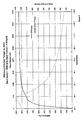
- Fig. 2 is a graph showing efficiency and output torque as a function of the speed ratio and output speed of the hydromechanical transmission shown in Figs. 1 and 6-13;
- Fig. 3 is a graph showing output torque as a function of the speed ratio of the transmission shown in Figs. 1 and 6-13;
- Fig. 4 is a graph showing the hydraulic pressure and flow rate as a function of the speed ratio and output speed of the transmission shown in Figs. 1 and 6-13;
- Fig. 5 is a graph showing the components of output horsepower contributed mechanically and hydraulically by the transmission shown in Figs. 1 and 6-13;
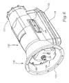
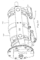
- Fig. 6 is a perspective view of a preferred embodiment of the transmission shown in Fig. 1;
- Figs. 7 and 8 are perspective views of the internal components of the transmission shown in Fig. 6, from above and below, respectively, with the housing removed for clarity of illustration;
- Fig. 9 is a plan view from below of the internal components of the transmission shown in Fig. 6;
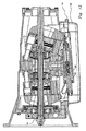
- Fig. 10 is a sectional plan view from above of the transmission shown in Fig. 6, along a horizontal section line through the longitudinal axis of the transmission;
- Fig. 11 is a sectional elevation of the transmission shown in Fig. 6 along a vertical section line through the longitudinal axis of the transmission, illustrating the transmission in neutral;
- Fig. 12 is a sectional elevation of the transmission like that of Fig. 11, illustrating the transmission at maximum torque;
- Fig. 13 is a sectional elevation of the transmission like that of Fig. 11, illustrating the transmission in reverse;
- Fig. 14 is a sectional elevation of the transmission shown in Fig. 6 along lines 14-14 in Fig. 10, showing the fluid flow channels in the manifold block for make-up fluid;
- Fig. 15 is a partial sectional elevation through the manifold block and control cylinder, showing the fluid flow channels for the control actuator shown in Figs. 11-13 and 49;
- Fig. 16 is a perspective view of the housing shown in Fig. 6 without the internal components;
- Fig. 17 is an end elevation of the housing shown in Fig. 16 from the input end;
- Fig. 18 is a sectional elevation of the housing shown in Fig. 16 along a vertical plane through the longitudinal axis of the housing;
- Fig. 19 is an end elevation of the housing shown in Fig. 16 from the output end;
- Figs. 21-24 are various views of the oil sump pan shown attached to the underside of the housing in Figs. 6 and 11-14;
- Figs. 25-31 are various views of the input end closure shown in Figs. 6 and 10-13;
- Figs. 32-36 are various views of the make-up pump housing shown in Figs. 10-13;
- Figs. 37-42 are various views of the manifold shown in Figs. 7-15;
- Figs. 43 and 44 are perspective exploded views of the brake shown in Figs. 10-13;
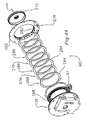
- Fig. 45 is a perspective exploded view of the drive components shown in Figs. 10-13;
- Fig. 46 is an enlarged sectional elevation of a portion of the pump drive components shown in Figs. 10-13;
- Fig. 46A is an exploded perspective view of selected pump guidance and preload components shown in Figs. 10-13;
- Fig. 47 is an exploded perspective view of selected motor components shown in Figs. 10-13;
- Fig. 48 is an exploded perspective view of components adjacent the manifold block shown in Figs. 7-14;
- Fig. 49 is an exploded perspective view of the control actuator shown in Figs. 7-9 and 11-15;
- Figs. 50-53 are various views of the cylinder block shown in Figs. 7-9 and 11-15 for receiving the components shown I Fig. 49
- Fig. 54 is a perspective view from the side of a swashplate version of the invention; and
- Fig. 55 is a sectional elevation of the embodiment shown in Fig. 54 on a vertical section plane through the longitudinal axis of the machine.
- Turning now to the drawings, wherein like reference characters designate identical or corresponding parts, and more particularly to Fig 1 thereof, the invention is illustrated in a schematic diagram in its preferred embodiment as a serial, continuously variable, double planetary design. It is specifically intended for use in most bus, truck and automobile applications powered by diesel and gasoline
internal combustion engines 40 where an overdrive final ratio is specified, although it would be useful in many other applications as well. The transmission is shown in Fig. 1 at hydraulic lock-up, with an input hydrostatic unit, or pump 50, at maximum displacement and the output hydrostatic unit, ormotor 60, at zero displacement. Thepump 50 has a non-rotating element and a rotating element driven by input torque delivered from aninput shaft 65, and is effective to pressurize a working fluid such as hydraulic fluid. Themotor 60 produces output torque delivered to anoutput shaft 76 when the motor is energized by the pressurized fluid from thepump 50. The two hydrostatic units can be simultaneously controlled from amaster controller 100, or they can be independently controlled, as described in detail below. - Rotary power from the
engine 40 is delivered, typically directly from the engine crankshaft to adrive coupling 64 at the input end of theinput shaft 65 of the transmission at the speed and torque of theengine 40, which can be operated at its optimum operating point for optimal efficiency and emissions. The transmission has a continuously variable ratio that enables it to convert the rotary input power from theengine 40 to rotary output power to the vehicle drive shaft at any desired speed within a range from reverse, through zero, to an overdrive speed, for example 1.5 times engine speed, and at a corresponding torque, with an overall efficiency of about 90% or higher, as shown in Fig. 2. - Input torque from the
engine 40 is transmitted through theinput shaft 65 to aplanet carrier 67 of a motor planet gear set 70 having planet gears 72 mounted in theplanet carrier 67 and engaged with aninner sun gear 73 and anouter ring gear 74. Theinput shaft 65 also drives amakeup pump 75 mounted in a front end closure of the transmission case. Thering gear 74 of the motor planet set 70 is connected drivingly to themotor 60 and to anoutput shaft 76. Atorque tube 78 connects thesun gear 73 of themotor planet 70 set to asun gear 83 of a pump planet set 80. The pump planet gear set has apump planet carrier 77 in which are mounted pump planet gears 82 that are engaged with the innerpump sun gear 83 and an outerpump ring gear 84. Thering gear 84 of the pump planet set 80 is connected drivingly to thepump 50. Theplanet carrier 77 of the pump planet set 80 can be grounded to the transmission case via areleasable brake 85. - In operation, when the transmission is in neutral, the
motor 60 is at a large displacement and thepump 50 is at zero displacement. In this neutral condition, rotation of the pump does not result in pressurized fluid being conveyed to themotor 60, and no reaction torque is transmitted to themotor ring gear 74 and coupledoutput shaft 76, hence, no output torque is delivered to the output shaft. Theoutput shaft 76 is stationary, hence themotor 60 and motor planet setring gear 74 are also stationary. Theplanet carrier 67 of the motor planet set 70 is spinning at input speed and therefore thesun gear 73 of the motor planet set 70 (and hence thesun gear 83 of the pump planet set 80) is rotating at 1+ (Rm/Sm) multiplied by the input speed, where Rm is the number of teeth in the motorset ring gear 74 and Sm is the number of teeth in the motor setsun gear 73. For example if the motorset ring gear 74 has 64 teeth and the motor setsun gear 73 has 32 teeth, the sun gears 73 and 83 will be rotating at 1 +(64/32) = 3 times input speed. With thepump planet carrier 77 fixed to ground via thebrake 77, thering gear 84 of the pump planet set 80 (hence the pump 50) is driven to rotate at a speed equal to the speed of the sun gears 73 and 83 multiplied by (Sp/Rp) in the opposite direction, where Sp is the number of teeth on the pump setsun gear 83 and Rp is the number of teeth on the pump set ring gear. For example, if the pump setsun gear 83 has 24 teeth and the pump setring gear 84 has 64 teeth, the pump setring gear 84 and hence the pump will be rotating at sun gear speed multiplied by -(24/64), or 9/8 input speed in the opposite direction from input. Since the pump is at zero displacement, there is no pumping and therefore no reaction torque can be generated at the pump. Hence it rotates freely and the transmission output speed is zero. - In actual operation, the
brake 85 will be released before the engine is turned on, disengaging thepump planet carrier 77 of the pump planet set 80 from ground, so theplanet carrier 77 can rotate freely. Therefore, no torque can be transmitted from thesun gear 83 to thepump 50. Without reaction torque transmitted back through the sun gears 83/73, no reaction torque can be transmitted from theinput shaft 65 to theoutput shaft 76, even if the pump is at some displacement when theengine 40 is first turned on. Thebrake 85 will not be applied until the control has moved the pump to zero displacement, as verified via a sensor signal to thecontroller 100. - Due to the two planet set configurations, the input torque is split into two parallel paths, as shown in Fig. 3. The first path is a direct mechanical path fed continually to the output shaft at the ratio of input torque multiplied by the inverse of 1 + the ratio of teeth on the motor set
sun gear 73 and the motorset ring gear 74, or (1/(1+(Sm/Rm))). The second path is a mechanical path fed continually to thepump 50 at a torque equal to the input torque multiplied by the inverse of 1 + the product of the ratios of the numbers of teeth on the motorset ring gear 74 to thesun gear 73, and the numbers of teeth on the pump setring gear 84 to thesun gear 83, or (1/(1+(Rm/Sm)) x Rp/Sp). - With the
brake 85 applied, grounding the pump gear setplanet carrier 77 to the housing, thepump 50 is stroked from zero displacement to give a small displacement. Thepump 50 is rotated by theinput shaft 65, acting through the two planetary gear sets 70 and 80, at input speed multiplied by (1+ (Rm/Sm)) x (Sp/Rp) to begin pumping. Fluid displaced by the pump flows directly throughflow channels output shaft 76 for delivery through anoutput drive connection 96 on theoutput shaft 76 to a drive shaft of the vehicle. Since thepump 50 is at a small displacement, a small amount of torque to thepump 50 results in a high pressure and small flow rate, as shown in Fig. 4. Since themotor 60 is at a large displacement the high pressure and small flow rate from thepump 50 results in a high output torque and low output speed, as shown in Fig. 3. This high 'hydraulic' output torque is added directly to the mechanical output torque as described above. Therefore the total output torque can be expressed as:
- It can therefore be seen, as illustrated in Fig. 3, that there is a total output torque comprising a fixed mechanical torque plus a variable hydraulic torque, and as the ratio of motor displacement to pump displacement decreases, the amount of hydraulic torque decreases. If the motor displacement is adjusted to zero then the hydraulic torque component becomes zero and the mechanical torque component becomes 100%.
- As the displacement of the
pump 50 increases, the flow rate from thepump 50 increases, and this increased flow causes themotor 60 and hence the motor planet gear setring gear 74 and theoutput shaft 76 to increase in speed. As the motor planet setring gear 74 increases in speed relative to the input shaft speed and hence the speed of the motor planet setplanet carrier 67, the speed of the motor planet setsun gear 73 decreases, causing the pump speed to decrease, as illustrated in Fig. 4. This has the effect of reducing the total system flow rate to a fraction of the flow rate in to a conventional hydrostatic transmission of the same capacity. The reduction will depend on the planet set ratios used; in this embodiment, the flow rate reduction is to approximatelyto . This flow rate reduction reduces the flow losses and noise levels normally associated with hydrostatic machines.
- As the motor displacement approaches zero and the pump displacement approaches its maximum, the pump speed approaches zero and motor speed approaches its maximum. When the
motor 60 reaches zero displacement, it can no longer accept fluid flow from thepump 50, so thepump 50 can no longer displace fluid and therefore stops rotating. This causes thesun gear 83 of the pump planet set 80,and hence thesun gear 73 of the motor planet set 70, to stop rotating. Thepump 50 now acts as a reaction unit for thesun gear 73 of the motor planet set 70. In this case, all the input torque now transfers through the motor planet set 70 to theoutput shaft 76. Due to the ratio of thesun gear 73 to thering gear 74 of the motor planet set 70, the output speed increases and the output torque decreases (e.g. by a factor of 1.5 to give an overdrive ratio of 0.667:1, as in the illustrated example). Since thepump 50 has been stroked to its full displacement, hydraulic pressure required to react the input torque is reduced to a minimum, as shown in Fig. 4, thus reducing to a minimum the hydraulic leakage losses and hydraulic loading of bearings. - With all the power now transferring through the motor planet set, as illustrated in Fig. 5, and the hydraulics acting only as a reaction unit to hold the motor planet set sun gear, the efficiency will be very high (95+%) as illustrated in Fig. 2, since the only losses are the normal gearset losses (approx. 2%), slippage on the
pump 50 due to leakage, and windage losses on themotor 60 due to the fact it is spinning at output speed under some pressure. To further increase the efficiency at this point a brake could be applied to lock thepump 50 to ground. This will help in two ways: first it will stop thepump 50 from slipping due to hydraulic leakage, and second, it will reduce the hydraulic system pressure to makeup pressure, therefore reducing the load and hence windage loss of the motor. The pump brake could be actuated by makeup pressure or by electro-mechanical means. - The transmission can drive the
output shaft 76 in reverse. Starting from the same conditions as in neutral, with the motor at maximum displacement and the pump at zero displacement, the controller strokes the pump in the opposite direction (i.e. a negative angle) causing fluid to flow in the opposite direction. This will cause themotor 60 to exert torque on theoutput shaft 76 to rotate in the reverse direction. Due to the planet set gear configuration, the mechanical torque, as described above, is still acting in the forward direction. Therefore the total output torque, in reverse, can be expressed as:
- A double planetary system (a motor planet set and a pump planet set) in a hydromechanical transmission has numerous benefits over a single planet set, including the following:
- 1. The motor planet set can be configured to give the desired final ratio of the transmission, and hence the ratio of mechanical torque transferred directly to the output shaft. In truck and automotive applications this is often an overdrive ratio in the range of 0.9:1 to 0.5:1. To configure a single planet set to give these final ratios causes the sun gear to rotate at relatively high speeds when the transmission is at very low ratios. If the pump were to be connected directly to this sun gear spinning at high speed, the high speed rotation of the pump could cause problems with centrifugal loading and noise, etc. By connecting the pump to a secondary planet set as described above, the pump speed is reduced, bringing it to within normal operating speeds.
- 2. By connecting the
pump 50 to a secondary planet set 80 as described above, the pump rotation is reversed from that of the motor rotation. Keeping the high and low pressure flow passages directly inline with each other between thepump 50 andmotor 60 enables the controls of both the pump and motor to stroke in the same direction, causing one to go to minimum displacement as the other goes to maximum displacement. This simplifies the control to some extent, as only one actuator is required to control both the pump and motor. This operation will be described later in conjunction with Figs. 6-15. - 3. The secondary planet set (the pump planet set 80) has a grounded member, such as the
planet carrier 77 of the pump planet set 80, that can be grounded by thereleasable brake 85. Releasing the brake frees theplanet carrier 77 from ground, thus enabling the grounded member to rotate so that no input torque can be reacted to output torque. This decoupling from ground of the grounded member can be useful in three operations:- a. When the
brake 85 is released at initial start up, no torque is transmitted to thepump 50 so it will not rotate. If thepump 50 has shifted away from zero displacement during rest, the vehicle will not lurch forward or backward when the engine is turned on so long as thebrake 85 is released. The brake will be applied only when the controller receives a signal from a sensor that thepump 50 andmotor 60 are at their correct displacements. Also, delaying the beginning of pump rotation allows time for make-up pressure and lubrication to reach the hydraulic units and their bearing interfaces before they start to rotate. - b. As the pump is stroked to give some displacement and hence some output speed, the
brake 85 can be modulated by means of a brake modulation valve 97 (described below) to give some slip to allow for a smooth start or "launch feel", in the same manner in which a clutch is slipped in a conventional manual transmission during acceleration from stop, or "take off". This eliminates the jerking or lurching 'kangaroo' takeoffs common with prior hydrostatic transmissions. - c. The brake can be released under driving conditions to decouple the engine from the drive wheels if so required during an emergency such as an engine seizure etc., or during towing.
- a. When the
- The transmission is controlled by means of the
electronic control unit 100. Theelectronic control unit 100 receives several electronic signals from the engine, transmission and vehicle, as shown in Fig. 1. Theelectronic control unit 100 processes these signals using a computer algorithm, specific to each particular vehicle, to produce a control signal which it sends to a transmissionratio control unit 105 having electro-hydraulic devices, such as a servomotor orstepper motor 110 operating apump modulation valve 115, and acontrol cylinder 116 by which the output ratio and speed of the transmission are controlled. This method of control offers great flexibility and enables the transmission to select the optimum ratio to achieve maximum system performance under a variety of operating conditions. - Depending upon the level of sophistication (and cost) of the control, it is possible to make the transmission behave in an adaptive, transparent manner, by reading many vehicle sensors such as applied brake force, steering angle, engine torque, rate of change of throttle position as well as throttle position etc. It is also possible to add manual features allowing the operator to select certain ratios.
- In this description it is assumed that the level of sophistication of control is such as to enable an efficient ratio selection to obtain high system performance and economy whilst maintaining the required level of safety and reliability. The
electronic control unit 100 receives signals from thedrive switch 118, throttle position sensor,input speed sensor 112,output speed sensor 114, and other sensors selected by the vehicle manufacturer, depending on the desired control sophistication. It processes these input signals and sends signals to thebrake modulation valve 97 and thestepper motor 110 for controlling thepump modulation valve 115 by which thecontrol valve 116 is operated to control the displacement of thepump 50 and themotor 60. - A mechanical safety interlock may be incorporated into the
drive switch 118 so that park, reverse and drive can only be selected when the vehicle is stopped or the brakes are applied, and the vehicle may only be started when the vehicle is in park, as in current automatic transmissions. - With the engine and electrical power off, the
hydraulic brake 85 that grounds thepump planet carrier 77 is released, allowing thepump planet carrier 77 to spin freely when torque is applied to thesun gear 83 of the pump planet set 80. Therefore any engine rotation will just rotate thepump planet carrier 77 and transmit no torque to theoutput shaft 76. - The engine is started with the transmission in park. The
controller 100 receives a signal from a contact in thedrive selector switch 118 when the engine ignition switch is operated which signals thecontroller 100 to de-energize or release thebrake 85, which allows the engine crankshaft to rotate without driving thepump 50. Theelectronic control unit 100 also sends a signal to thestepper motor 110 to send the transmission to the neutral position, just in case the vehicle was stopped with the transmission in a ratio other than neutral. When theengine 40 is at idle speed the make uppump 75 produces enough pressure and flow to ensure that thehydraulic units hydraulic brake 85 by way of thebrake modulation valve 97, and to sufficient lubrication pressure and flow or prevent damage to moving parts. - Position sensors are attached to the non-rotating elements of the hydraulic units to generate signals that are transmitted to the
electronic control unit 100 that the transmission is in neutral (i.e. pump at zero displacement, motor at maximum displacement), thus adding another level of control, safety, and reliability. - With the
engine 40 at idle and the foot brake applied, thedrive selector switch 118 is moved to the "drive" mode. When the foot brake is released and the throttle is depressed theelectronic control unit 100 signals thebrake modulation valve 97 to gradually apply thehydraulic brake 85 while also signaling thestepper motor 110 of thetransmission ration controller 105 to stroke the transmission to some forward ratio. Theelectronic control unit 100 can determine the required 'take off' characteristic of the vehicle, i.e. whether acceleration is to be slow and soft, hard and fast, or high torque (as in towing) from the rate of depression or force on the accelerator pedal and the load or resisting torque in theoutput shaft 76. The desired "take-off" is achieved by the rate of application of thebrake 85 and the rate of change of the speed ratio produced by thestepper motor 110. By modulating thebrake modulation valve 97, all various kinds of launch characteristics can be achieved. - When the
output speed sensor 114 registers a certain speed, theelectronic control unit 100 signals thebrake modulation valve 97 to apply full brake force and fully lock thepump planet carrier 77. Thestepper motor 110 alone now controls all transmission ratios. - By monitoring the throttle position, engine speed and the load applied to the engine, the
electronic control unit 100 can produce the required vehicle speed requested by the operator. By comparing these values to a preprogrammed operating schedule theelectronic control unit 100 can vary the transmission ratio (via the stepper motor 110) to achieve the most effective driving regime. By comparing the input to output speed signals theelectronic control unit 100 can determine the transmission ratio and make continual changes to thestepper motor 110 to achieve this regime. It is also possible to add a driving style switch, such as sport or economy mode, to enable theelectronic control unit 100 to read different operating schedules and therefore give different driving conditions as requested by the operator, enabling theelectronic control unit 100 to select the most efficient ratio for greatest economy, or achieving the highest performance for acceleration etc. - As the vehicle is slowed down to a stop by the operator, the transmission is stroked by the
electronic control unit 100 towards neutral. At the point when the transmission is in neutral, the output shaft becomes hydraulically locked, thus locking the driving wheels of the vehicle. This could cause some slight skidding of the tires at this point, which would be undesirable. To alleviate this condition, a small dump (short circuit)valve 117 may be inserted between the high-pressure and low-pressure lines hydraulic units hydraulic motor 60 to 'freewheel'. Thedump valve 117 can be operated electronically and actuated by theelectronic control unit 100 just before the neutral position is achieved. Although the motor will be very close to its maximum displacement at this time, thedump valve 117 need only accept a small flow rate as the motor speed will be virtually zero at this point. Once the vehicle is stopped theelectronic control unit 100 can close thedump valve 117 and return the transmission to its 'holding neutral' position. - When the output speed approaches zero speed the
electronic control unit 100 may be programmed to de-energize thebrake modulation valve 97 therefore releasing thepump planet carrier 77. Although this is not necessary for the transmission to stay in the neutral mode, it readies the transmission for the next launch. - As mentioned earlier, the level of sophistication of control can be increased by using the variety of now common vehicle sensors, and more complex computer algorithms to achieve an adaptive transmission control, monitoring the driver's inputs and continually updating the operating schedules.
- It is possible for the
electronic control unit 100 to perform system diagnostic checks, by comparing the feedback signal from the servomotor orstepper motor 110 and actual ratio achieved and/or by measuring system and make up pressures and alerting the driver if these values fall beyond predetermined specifications. - Under certain circumstances, such as driving on gravel or icy roads or going down steep hills, and for maneuvering whilst towing heavy loads, it may be desirable for safety and enhanced control reasons to limit the maximum ratio that the
electronic control unit 100 can select. For this reason, a low gear position is provided on thedrive selector switch 118. This low gear mode can be activated either from a stationary start or on the fly from the drive mode. If low gear is selected from the park position, the transmission will start in the same manner as in drive mode, except that the transmission will not stroke beyond a predetermined ratio, staying at this lower maximum ratio if the throttle position is sufficiently depressed. Theelectronic control unit 100 will also use a different operating schedule to determine the transmission ratio, as starting in low gear will signify that a low speed, high torque demand is required, as in towing and maneuvering a heavy object. Also when driving in the low gear, due to the fact that a low ratio will be maintained, the driver will be offered more control from the throttle and more responsive engine braking at the expense of vehicle speed. This is particularly useful when towing heavy loads up and down hills. - If the low gear is selected whilst the vehicle is in motion and in the drive mode, low gear operation will take effect only when the vehicle is moving slower than a predetermined speed. At that speed, the
electronic control unit 100 will then change the transmission ratio smoothly and slowly to suit the different operating schedules. The transmission will then operate as indicated above. If the transmission is placed into drive mode from low gear, theelectronic control unit 100 will change the transmission ratio smoothly and slowly to suit the new operating schedule. - If the neutral mode is engaged on the
drive selector switch 118, theelectronic control unit 100 will assume that the vehicle needs to coast or be free-wheeled. To achieve this, theelectronic control unit 100 will move thebrake modulation valve 97 to release thebrake 85 and disconnect engine power from theoutput shaft 76, and will stroke the transmission to full overdrive, (i.e. motor at zero displacement and pump at maximum displacement). This will enable the output shaft to rotate freely without any hydraulic pumping, causing the now releasedpump planet carrier 77 to rotate freely so that the vehicle can be externally maneuvered or towed. - In the event of a power failure or failure of the
electronic control unit 100 when the transmission is not in overdrive, a manual control may be used to move the servomotor orstepper motor 110 to the full overdrive position. - Reverse mode can be selected with the
engine 40 at idle and the foot brake applied. When the foot brake is released and the throttle is opened, theelectronic control unit 100 signals thebrake modulation valve 97 to gradually apply thehydraulic brake 85 while also signaling thestepper motor 110 to stroke the transmission to some reverse ratio. Theelectronic control unit 100 will modulate thebrake modulation valve 97 to give a smooth take off in reverse. There is only a limited amount of ratio available in reverse thereby limiting the speed in reverse to a safe and acceptable amount. Theelectronic control unit 100 will determine the reverse ratio from the throttle position and engine speed. - A preferred embodiment of the transmission shown schematically in Fig. 1 is shown in Figs. 6-15 as a serial, bent axis, double planetary, hydromechanical, continuously variable transmission. This transmission has a
housing 120, shown in Figs. 6, and 10-20, for enclosing an operating assembly, shown in Figs. 7-13. Thehousing 120 has aninput end 119 from which protrudes theouter end 64 of theinput shaft 65, and an input endperipheral flange 123 by which the transmission can be attached to thevehicle engine 40. Thehousing 120 also has anoutput end 121 from which protrudes theoutput end 96 of theoutput shaft 76. Thehousing 120 has a large opening 122 at the underside surrounded by aperipheral flange 124 to which asump pan 125, shown in Figs. 6, 11-14 and 21-24, is attached by conventional removable fasteners (not shown) for easy access to the interior of thehousing 120. - A
circular end closure 126, shown in Figs. 6 and 10-13, and shown in detail in Figs. 25-31, is fastened into acircular recess 127 in the input end opening of thehousing 120 bymachine screws 128.Holes 129 around the outside of theend closure 126 receive thescrews 128 which are threaded into tapped holes inbosses 130 in the inside of thehousing 120 spaced around thecircular recess 127. Thecircular end closure 126 has acentral opening 131 through which the end of theinput shaft 65 extends, and a centralcylindrical recess 132 for receiving the make-uppump 75. The make-uppump 75 can be any suitable type of pump for the application, such as a vane pump of known construction, having a pump rotor driven by theinput shaft 65 in apump housing 133, shown in Figs. 10-13 and Figs. 32-36. - An
annular cylinder 134 in the inner face of thecircular end closure 126, concentric with thecylindrical recess 132, receives thebrake 85, as shown in Figs. 10-13 and shown exploded in Figs. 43 and 44. Thebrake 85 enables thepump 60 and downstream components of the operating assembly to be smoothly engaged and disengaged from theinput shaft 65, as described above and in detail below. - The operating assembly shown in Figs. 7-13 includes the input
hydrostatic pump unit 50 and the outputhydrostatic motor unit 60 hydraulically related to each other through thefluid passages stationary manifold block 140 between thepump 50 and themotor 60. Thepump 50 andmotor 60 are mechanically related through the first variable ration gear set such as an epicyclic planetary or differential gear set 70 and the second similar gear set 80. Thestationary manifold block 140, shown in Figs. 7-15 and shown in detail in Figs. 37-42, is connected to thehousing 120 through a pair ofidentical connector links 145, as shown in Figs. 10, 14 and 48. Eachconnector link 145 has alongitudinal stiffening rib 146 along its outside face, primarily to resist loads exerted on thelink 145 by the yokes, discussed below. Thelinks 145 are fastened byscrews 148 intorecesses 149, one in each side of thestationary manifold block 140, and project out throughmanifold 140 in the housing without unnecessary enlargement of thehousing 120. - As shown in Figs. 7-10, and 47, an
input yoke 151 and anoutput yoke 152 are each pivotally connected to the connector links 145 byswivel barrels yoke arms output yokes yokes horizontal axes integral stub shafts stub shafts axes longitudinal axis 174 of the machine at the center of curvature of two convexspherical bearings 176 and 178 on which annular pump andmotor cylinder blocks longitudinal axis 174 of the machine coincides with the axis of theinput shaft 65 and thecoaxial output shaft 76. - Each
yoke control clevis control actuator 192, shown in detail in Figs. 8, 9, 11-13 and 49. Theactuator 192 includes anactuator cylinder block 189, shown in detail in Figs. 50-53, which is fastened to the underside of thestationary manifold block 140, as shown in Figs. 8 and 9, so it is stationary relative to themanifold block 149 and thehousing 120. The control links 188 and 190 are pinned to the ends ofbars control pistons cylinder 195 in thecylinder block 189 under the influence of hydraulic fluid controlled by aspool 198 connected to arod 199 moved by the servomotor orstepper motor 110 to control the tilt angle of theyokes actuator 192 makes control of the control yokes 151 and 152 simple, consistent and reliable. The stationary nature of thestationary manifold block 140 also affords access into the fluid circuit for simple and 152 simple, consistent and reliable. The stationary nature of thestationary manifold block 140 also affords access into the fluid circuit for simple connection of make-up fluid flow lines by way of a tapped port 201. External taps into the pressure channels for regenerative braking/acceleration and hydraulic power take-off are also made possible without the use of rotating interfaces or the like by thestationary manifold block 140. - The make-up
pump housing 133, shown in Figs. 32-36, has acylindrical recess 202 in which a rotor 204 andvanes 205 of the make-uppump 75 are mounted and driven by theinput shaft 65, as shown in Figs. 10-13, for pressurizing fluid drawn from thesump pan 125 to recharge the fluid circuit with fluid lost through leakage, and to pressurize theactuator 92. The hydraulic fluid from the make-up pump also is use to lubricate the bearings and sliding interfaces in the transmission. - As shown in Figs. 7, 10 and 47, the annular pump and
motor cylinder blocks hydrostatic units cylinders motor pistons 210 and 212, respectively, are disposed, as shown in Figs 11-13. All thepistons 210 and 212 are identical, so a description of one will suffice for all. Each piston, as best seen in Fig. 46, has aspherical head 214 and acylindrical base 216 connected by acylindrical shank 215. Thecylindrical base 216 tapers toward thehead 214 from a pair ofannular grooves axial bore 222 extends completely through eachpiston 210 and 212 for conveying fluid from the cylinders in the cylinder block on one side of the manifold block, through thefluid passages - The spherical heads of the
pistons 210 and 212 are seated in spherical sockets 224 in apump torque ring 226 and amotor torque ring 228, each having a flat face in contact with themanifold block 140. The only two rotating fluid transfer interfaces in the transmission are the interfaces between the two sides of themanifold block 140 and the two torque rings 226 and 228. No torque is transmitted through these interfaces so distortion under torque load is minimal, thereby reducing leakage which otherwise could be caused by distortion of the torque ring face under load. As shown in Fig. 48, the torque rings 226 and 228 are supported for rotation on a ring of cagedneedle bearings 230 surrounding a bearingsupport annulus 232 fastened to the center of themanifold block 140 byscrews 234, one on each side of the manifold block. - As shown in Figs. 11-13, 46 and 47, the piston heads 214 are held in the sockets 224 of the torque rings 226 and 228 by
retainer rings 238 which are integral with the ring gears 84 and 74. The retainer rings 238 are fastened to the torque rings 226 and 228 byfasteners 240 which also provide a torque path between the ring gears 84 and 74 and the torque rings 226 and 228. - The outer ends of the
cylinders pucks 236 best seen in Fig. 46. Thepucks 236 each have aseal groove 237 for receiving a seal ring (not shown) and aspring groove 239 for receiving an annular wave spring which biases the puck outward against flat annular bearing surfaces 242 and 244 on the inner faces of theyokes yoke 152. The floating puck can move slightly axially and tilt slightly to follow a momentary perturbation or deviation from flatness of the yoke inner bearing surfaces 242 and 244. A small central hole and cylindrical recess in the outer face of eachpuck 236 provides a hydrostatic bearing which just reacts the fluid force inside thecylinders yokes - An axial biasing force is exerted to urge the
cylinder blocks grooves 247 in the flutedaxial bore 209 of the pump andmotor cylinder blocks spherical ring 248 and 250 which is guided for tilting on thespherical bearings 176 and 178 about the centers of curvature of the spherical interfaces of the spherical rings and spherical bearings. Thespherical rings 248 and 250 guide the pump andmotor cylinder blocks spherical bearings 176 and 178 for rotation and tilting about their respective centers of mass. Those centers of curvature coincide with the intersection of theaxes stub shafts longitudinal axis 174 of the machine, as shown in Fig. 10, so that the axes of rotation of the cylinder blocks always intersects the tilting axis of theyokes spherical rings 248 and 250 to thespherical bearings 176 and 178, and thence (on the pump side) to apump preload flange 252, shown most clearly in Figs. 46 and 46A. The radial outer surface of thepump preload flange 252 is splined at 253 and engaged withsplines 254 in the bore of thering gear 84. Thesplines 254 are shallower than the teeth of thering gear 84, so thepreload flange 252 can slide into thering gear 84 only about one quarter of the way until it is engaged by the higher teeth of thering gear 84. This engagement enables the axial force exerted on thepreload flange 252 by thespherical bearing 176 to be transmitted to thering gear 84 and itsintegral retainer ring 238 and thence to thetorque ring 226 for ensuring contact of thetorque ring 226 against the manifold block during start-up so that the fluid system remains sealed and make-up pump pressure can be developed by the make-uppump 75 for lubrication flow and charging the system during start-up. - As shown most clearly in Figs. 45 and 46, a
stator tube 260 for coupling thepump planet carrier 77 to thebrake 85 includes an externally splinedinner end 262 engaged with an internally splinedtubular extension 264 on thepump planet carrier 77. Thestator tube 260 surrounds theinput shaft 65 and extends from theplanet carrier 77 to an outersplined end 266 engaged with an internallysplined ferrule 268 projecting inwardly from abrake flange 270. Thebrake flange 270 has an outer peripheralcylindrical flange 272 that is castellated or toothed on its outer radially facing surface to receive inwardly projectingradial teeth 274 of threeclutch discs 276. Thebrake flange 270 and theclutch discs 276 lie concentrically within abrake ring 278 having an outerradial flange 280 that is fastened to thecircular end closure 126 and has an axialcylindrical section 282 concentrically surrounding thecylindrical flange 272. The interior of the axialcylindrical section 282 is grooved or slotted to receiveteeth 284 projecting radially outward from the outer end of a plurality of annularclutch plates 286 bracketing theclutch discs 276. A radial lip at the end of the axialcylindrical section 282 prevents theclutch discs 276 andplates 286 from being pushed out of the end of the axialcylindrical section 282. Anannular brake piston 288 is seated in theannular cylinder 134 and is movable axially under influence of fluid admitted in theannular cylinder 134 behind thebrake piston 288 to exert a precisely controlled axial force on theclutch plates 286 and theclutch discs 276 to transmit torque from thebrake flange 270 to thebrake ring 278 and thence to the housing. The fluid pressure released into theannular cylinder 134 for acting against thebrake piston 288 is controlled by thebrake modulation valve 97, which is a commercially available pulse modulated solenoid controlled fluid valve. In this way, the reaction torque transmitted from the pump planet carrier to ground, and hence the torque transmitted to thepump 50, is precisely controlled by thecontroller 100 through thebrake modulation valve 97. - In operation, when the starter of the vehicle engine is energized, the
brake 85 is released to allow theplanet carrier 77 to spin freely, preventing torque from being transmitted to the pump. The starter motor has a much lighter load without having to rotate the pump and there is no chance that the vehicle could surge forward or backward because of an inadvertent adjustment of the pump displacement. - The
rotating input shaft 65 rotates the make-uppump 75 and fluid pressure at make-up pressure is developed in the system. Pressurized fluid flows from the make-uppump 75 through aradial hole 280 in theinput shaft 65 and through anaxial hole 282 and then out through anotherradial hole 284 into anannular space 286 between theinput shaft 65 and thestator tube 260. The fluid flows along theannular space 286 and lubricates a needle bearing between theplanet carrier 77 and thesun gear 83, shown in Fig. 46. The fluid continues flowing along theannular space 286 and squirts up through ahole 290 to be deflected by anoil deflector 292 into an axial hole in apinion shaft 294 on which the pump planet gears 82 are mounted for rotation onneedle bearings 296. Thoseneedle bearings 296 are lubricated by hydraulic fluid flowing from the axial holes and out radial holes in thepinion shaft 294. The motor planet gears are likewise lubricated by fluid flowing through radial and axial holes in the end of theinput shaft 65 and into similar fluid flow passages in and around the bearings and gears inside themotor 60 as illustrated in Figs. 10-13. - With system pressure now up to the pressure of the make-up pump, sufficient pressure is available to operate the control system. The
control unit 100 sends a signal to the servomotor orstepper motor 110, mounted on abracket 298 to move thecontrol rod 199 and thespool valve 198 threaded onto therod 199 to a zero displacement position from which forward or reverse acceleration can be commenced. The driver selects forward or reverse on thedrive selector switch 118 and depresses the accelerator. Thecontroller 100 senses the rate and extent of depression of the accelerator and adjusts the transmission accordingly by sending a signal to thestepper motor 110 to move the control rod and spool valve to a new position at the desire speed, while also adjusting the throttle to increase the engine speed to some designated speed of operation, preferably at a rate of increase and to an operating speed that will result in optimal efficiency and minimal emissions. The position of thespool valve 198 controls the position of afollower spool sleeve 200 which in turn controls the position of thepump control piston 194, using system pressure delivered to a larger cross-sectional area behind thestep 299 in thepiston 194. Both pump control piston andmotor control piston 196 are biased toward the left in Figs. 11-13 by fluid admitted into annular spaces between thepistons holes openings actuator cylinder block 189, and through check valves in those openings, so the pressure delivered to thecontrol actuator 115 is always at system pressure even if the vehicle is running down hill and the motor is operating as a pump. - When more displacement of the pump is desired, the
control rod 199 is pulled further to the right in Figs. 11-13 and 49 to cause thepump control piston 194 to move to the right correspondingly. Eventually, the pump control piston will engage the end of themotor control piston 196 and the twocontrol pistons - One of several variations of this invention that are made possible by its unique arrangement is the swashplate version shown in Figs. 54 and 55. This version is identical in its structure and operation with the exception that the cylinder blocks do not tilt with the yokes, as in the embodiment of Figs. 6-15, but instead the cylinder blocks 180' and 182' rotate flat against the
manifold block 141. The pistons now face outward and the piston heads are captured inslippers 310 and bead against a flat face of apump swashplate 315 and amotor swashplate 316. The swashplate angles are controlled by acontrol actuator 115 as in the prior embodiment. Theswashplates elongated links 320 as shown in Fig. 54. - The advantage of the swashplate design is that the housing can be made smaller because the excursion of the tilting swashplates is less that the corresponding excursion of the tilting yokes 151 and 152 and their cylinder blocks. The disadvantage of the swashplate design is that it tends to wear faster because of the lateral forces exerted by the pistons in the cylinders. The resulting frictional forces also result in somewhat higher internal losses, so swashplate hydrostatic units have a bit lower efficiency that the bent axis units used in the embodiment of Figs. 6-15.
- Thus, the preferred embodiment of the invention described above attains the objects enumerated above, and others. Notable among its many features and benefits are the following:
- 1. Actual neutral with zero displacement.
- 2. The clutch/
brake 85 allows smooth starting without the usual jerkiness of a hydrostatic transmission by allowing controlled limited slipping. Thebrake modulation control 97 allows thebrake 85 to be applied gradually for a soft and gentle "launch feel" or a sudden fast acceleration, or anything in between, by using the accelerator peddle position of rate of depression as an input to the pulse width solenoid on thebrake modulation valve 97. Releasing thebrake 85 allows easier starting of the engine because the inertial and fluid resistance is removed, thereby reducing the load on the starter. - 3. The working fluid system can be pressurized with the
brake 85 decoupled, using the make-uppump 75, so that any slip of the pump setting from zero displacement position won't cause unintended surges when engine is started. - 4. If the
engine 40 seizes, the output shaft 76 (and the vehicle wheels) can free-wheel by disengaging thebrake 85 and stroking themotor 60 to zero displacement (for example, by valving the motor output to the pumpmodulation control valve 115, so it is pressurized toward the lock-up position.) - 5. The axial load of the torque rings against the manifold block is proportional to pressure, so the sealing force increases as needed to contain the higher pressure.
- 6. Axial fluid pressure force is reacted internally through the links and is not carried by the housing, so the housing can be made light and economical. Torque on the yokes is reacted through the links instead of the housing. Loads are reacted internally, isolated from the housing, so loads on the housing are reduced; hydraulic ripple, hydraulic pressure pulses, are isolated from the housing, reducing noise, vibration and harshness.
- 7. A stepper motor controls the position of a leader/follower valve, whose position controls the position of the transmission ratio control pistons. The stepper motor is electrically controlled by a controller operating in accordance with control algorithms specific to the particular vehicle, using inputs selected by the vehicle manufacturer, such as throttle position, transmission drive selector switch, engine speed, vehicle speed, engine torque, load (as detected by a torque sensor on the output shaft), operator preference controls (e.g. "economy", "performance", etc.) and other inputs relevant to operation of a motor vehicle. The transmission is thus able to function in a wide variety of vehicles by adapting through the inputs and algorithms preferred by the vehicle designers.
- 8. A valve in the manifold block can be opened to dump pressure into a hydraulic accumulator or just to sump if the driver wants to coast down hill or to a stop light, so the motor doesn't stroke to full displacement and lock up the wheels.
- 9. Holding the vehicle on position on a hill without braking (e.g. while at a traffic light or when starting the engine) is made possible because the motor is at full displacement and the pump is at zero displacement, so the wheels would have to drive the motor to pump fluid, but there is no place for the fluid to go so the output shaft is locked.
- 10. Engine starting using fluid pressure stored, e.g. in an accumulator, is possible by setting the pump to maximum displacement and the motor to zero displacement, and opening a "starter valve" to apply fluid pressure to the suction side of the manifold and let the pressure side discharge to sump. This will drive the engine in the driving direction for starting similar to using a conventional starter motor. As soon as the engine starts, the input shaft speed increases and the brake/clutch is released to allow the engine to spin the input shaft without applying torque to the pump. The "starter valve" is reset to the drive position and normal driving operation is resumed.
- 11. The transmission can be operated as a fluid power source for hydraulic power applications such as remote hydraulic motors and hydraulic cylinders. The pump is set to maximum displacement and the motor to zero displacement. A power take-off valve (not shown) is opened to allow fluid to flow to and from the manifold through an external fluid circuit to the power application. The engine is operated to give the desired flow rate to operate the power application as long is it is needed, and then the power take-off valve and the transmission pump and motor are reset to normal driving position.
- 12. Pump and motor stroke control is simple and reliable because the yoke is attached to ground.
- 13. Fluid connections into the fluid circuit are easy and leak-free because they can be made in the manifold block, which is fixed to ground, so they don't have to pass through a rotating interface.
- Obviously, numerous modifications and variations of the preferred embodiment described above are possible and will become apparent to those skilled in the art in light of this specification. For example, many functions and advantages are described for the preferred embodiment, but in many uses of the invention, not all of these functions and advantages would be needed. Therefore, we contemplate the use of the invention using fewer than the complete set of noted features, benefits, functions and advantages. Moreover, several species and embodiments of the invention are disclosed herein, but not all are specifically claimed, although all are covered by generic claims. Nevertheless, it is our intention that each and every one of these species and embodiments, and the equivalents thereof, be encompassed and protected within the scope of the following claims, and no dedication to the public is intended by virtue of the lack of claims specific to any individual species. Accordingly, it is expressly intended that all these embodiments, species, modifications and variations, and the equivalents thereof, are to be considered within the spirit and scope of the invention as defined in the following claims, wherein we claim:
Claims (16)
- A continuously variable transmission comprising:two hydraulic units including a pump (50) and a motor (60), each having a rotational element (180, 182) and a grounded reaction element (151, 152), at least one of said hydraulic units (50) being variable displacement;a control system (100) for controlling said displacement of said one hydraulic unit;a variable ratio motor gearset (70) having first, second and third meshing gear elements (72, 74, 73), and a variable ratio pump gearset (80) having first, second and third meshing gear elements (82, 84, 83);an input shaft (65) connected to said first gear element (72) of said motor gearset (70);an output shaft (76) connected to said second gear element (74) of said motor gearset and to said rotational element (182) of said second hydraulic unit (60);said third gear element (73) of said motor gearset (70) being connected to said third gear element (83) of said pump gearset (80);said second gear element of said pump gearset being connected to said rotational element of said first hydraulic unit;said two hydraulic units being hydraulically connected such that the displaced fluid from the first hydraulic unit flows to the second hydraulic unit and vice versa;characterized by a brake (85) releasably connecting said first element (82) of said pump gearset (80) to ground;
whereby, input torque applied to said input shaft (65) is transmitted therethrough to said pump (50), when said brake (85) is engaged, by way of said first and third elements (72, 73) of said variable ratio motor gearset (70) and thence by way of said third, first and second elements (82, 84, 83) of said variable ratio pump gearset (80), reacting through said engaged brake (85) to ground, to rotate said pump (50) and pressurize a working fluid in said pump; said transferring of said input torque from said input shaft (65) to said pump (50) creating a reaction torque which is transferred through said second element (74) of said variable ratio motor gearset (70) to said output shaft (76), said pressurized fluid being conveyed through an opening in a manifold block (140) between said hydraulic units to said motor (60) and energizing said motor (60) to produce motor torque that is transferred to said output shaft (76) in addition to said reaction torque as output torque in said output shaft (76). - A continuously variable transmission as defined in claim 1, wherein:said hydraulic units (50, 60) and said two variable gearsets (70, 80) are configured to give a desired final ratio, and to split said input torque into first and second parallel paths, said first parallel path being a direct mechanical path to the output shaft (76), and second parallel path being through said first and second hydraulic units (50, 60);said second hydraulic unit (60) and said first hydraulic unit (50) having a ratio of displacements that multiplies torque through said second parallel path, thereby adding to torque transmitted through said first parallel path;whereby, adjustment of said motor displacement to zero reduces torque multiplication from the hydraulic units (50, 60) to zero so they act only to react torque from the mechanical torque of said first parallel path and so all said input torque and energy passes directly through said motor gearset (70) to said output shaft (76), and stroking said motor (60) to maximum displacement and said pump (50) to zero displacement places said transmission in a "holding neutral" setting for holding a vehicle in a stationary position, wherein said motor (60), and hence said output shaft (76), can not rotate in any direction as said pump (50) can not accept any fluid discharged from said motor (60).
- A continuously variable transmission as defined in claim 2, wherein:stroking of variable displacement pump (50) in either direction from said zero displacement position thereof changes direction of fluid flow from said pump (50) to said motor (60) and drives said motor (60) and hence said output shaft (76) in either forward or reverse direction;whereby said transmission hydraulically multiplies torque in both forward and reverse, without having to change any gearing, as follows:where A = 1/(1+(Rm/Sm)) x Rp/Sp x motor displacement/pump displacement).


- A continuously variable transmission as defined in claim 1, further comprising:control apparatus (105, 100) for stroking said motor (60) to zero displacement and releasing said brake (85) to disconnect said first element (82) of said pump gearset (80) from ground;whereby, said releasing of said brake (85) enables said output shaft to freely rotate in either direction, regardless of pump displacement or input speed, and said output shaft and power applications driven thereby are disconnected from a prime mover.
- A continuously variable transmission as defined in claim 1, wherein:said first element (82) of said pump gearset (80) is connected to ground by means of said releasable brake (85), and can be released to disengage a prime mover from the transmission when desired;whereby disengagement of said brake (85) at startup allows time for make-up pressure and lubrication to reach the hydromechanical units (50, 60) before they start rotating, and gradual engagement of said brake (85) during start up, launch and driving, facilitates take off characteristics,
- A continuously variable transmission as defined in claim 1, wherein:said pump and motor hydraulic units (50, 60) are both variable displacement bent axis units, hydraulically connected in series through said stationary manifold block (140), through which hydraulic fluid passes from said pump (50) to said motor (60), and vice versa;said pump (50) having pump cylinders (206) containing pump pistons (210) with piston heads (214) fixed in a pump torque ring (226) in contact through a hydraulic interface with one side of said stationary manifold block(140), said pistons (210) having axial bores (222) through which said fluid pressurized in said pump (50) passes from said pump (50) and thence through said manifold block 140);said motor (60) having motor cylinders (208) containing motor pistons (212) with motor piston heads (214) fixed in a motor torque ring (228) in contact with a side of said manifold block (140) opposite said one side through a hydraulic interface, said motor pistons (212) having axial bores (222) through which fluid pressurized in said pump (50) passes from said manifold block (140) into cylinders (208) of said motor (60) to energize said motor (60) and convert energy in said pressurized fluid to torque.
- A continuously variable transmission as defined in claim 6, further comprising:a spherical bearing (176, 178) in each of said hydraulic units, each spherical bearing (176, 178) having a center of curvature lying on a pivotal axis of a yoke barrel (154, 156) by which a yoke (151, 152) is pivotally connected to each side of said manifold block (140) for supporting said rotational elements (180, 182) of said hydraulic units;said rotational elements of both of said hydraulic units (50, 60) include cylinder blocks (180, 182) which are guided on inner axial ends thereof by said spherical bearings (176, 178);springs (246) biased between said spherical bearings (176, 178) and said cylinder blocks for pre-loading said cylinder blocks (180, 182) against said yokes (151, 152) and for pre-loading said torque rings (226, 228) against said stationary manifold block (140);whereby said spring pre-load provides an initial hydraulic seal at said hydraulic interfaces.
- A continuously variable transmission as defined in claim 6, wherein:said pump hollow pistons (210) each include a spherical head (214) at one end, said spherical head (214) being fixed to said pump torque ring (226) for articulation relative thereto during operation of said pump (50);whereby said piston (210) is free to articulate as said cylinders (206) rotate whilst maintaining a sufficient length of engagement and hydraulic sealing in said cylinder bore, and said hollow pistons (210) pass fluid flow from said cylinders (206) to said stationary manifold (140) and vice-versa, free of substantial restriction, as well as reducing the weight of the piston (210) and thereby reducing piston friction due to centrifugal loading.
- A continuously variable transmission as defined in claim 1, wherein:said pump and motor hydraulic units (50, 60) are variable displacement bent axis units having rotating elements rotating about their own centers of mass;whereby said rotating elements are inherently balanced and can be rotated at high rotational velocity and therefore at high power levels.
- A continuously variable transmission as defined in claim 1, wherein:both of said hydraulic units (50, 60) are variable displacement units, each having cylinder blocks (180, 181) supported by yokes (151, 152) that are linked to each other;whereby all internal separating loads are resolved internally through said yokes and linking structure.
- A continuously variable transmission as defined in claim 10, further comprising:balance pucks (236) between said cylinder blocks (180, 181) and said yokes (151, 152) and having hydrostatic bearings at an interface between said pucks (236) and said yokes (151, 152) for supporting said cylinder blocks (180, 181) of both hydraulic units (50, 60) on said yokes (151, 152); andsaid balance pucks (236) being axially movable relative to said cylinder blocks (180, 181) to accommodate some deflection of said yokes (180,181);whereby said balance pucks (236) move axially in the event of yoke deflection whilst said balance pucks (236) remain substantially flat against said yokes (180, 181) to maintain integrity of said hydrostatic bearing.
- A continuously variable transmission as defined in claim 1, wherein said control system (100) comprises:a motor control piston (196) movable in a control cylinder (195) between positions corresponding to zero displacement and maximum displacement of said motor (60);a pump control piston (194) movable in a pump control cylinder (195) between positions corresponding to maximum displacement in reverse, through zero displacement, and maximum displacement in forward, said pump control piston (194) having a back face, disposed in fluid engaging orientation in said pump control cylinder (195);control links (190) between said motor control piston (196) and said motor yoke (152) for controlling the displacement of said motor (60) by controlling said position of said motor control piston (196), and control links (188) between said pump control piston (194) and said pump yoke (151) for controlling the displacement of said pump (50) by controlling said position of said pump control piston (194);a motor piston biasing force acting on said motor control piston (196) to bias said motor yoke (152) toward a maximum tilt position thereof, wherein said motor displacement is at a maximum;a pump piston biasing force acting on said pump control piston (194) to bias said pump yoke (151) toward said maximum displacement of said pump in reverse;a modulating valve (115) through which system pressure is tapped off from said manifold block (140) and is fed through to said back face of said pump control piston (194) for controlling said pump piston position;whereby system pressure admitted by said modulating valve (115) into said pump control cylinder (195) and acting on said back face of said pump control piston (194) generates a pressure force that overcomes said pump piston biasing force and said motor piston biasing force to cause said pump to stroke toward said maximum displacement thereof in the forward direction to a position determined by said modulating valve (115).
- A continuously variable transmission as defined in claim 12, wherein:said motor piston biasing force and said pump piston biasing force are hydraulic forces exerted by transmission fluid at system pressure admitted to said pump control cylinder (195) and said motor control cylinder (195) and applied against front faces of said pump and motor control pistons (194, 196).
- A continuously variable transmission as defined in claim 12, wherein:said biasing force is exerted by system pressure delivered to said piston faces via internal passages in said manifold block (140) for conveying system pressure to said back surface of said motor control piston (196) for pressurizing said motor control cylinder (195) and exerting a pressure force against said back face of said motor control piston (196) with system pressure, said system pressure acting on said motor control piston back area to bias said motor yoke (152) toward a maximum tilt position thereof, wherein said motor displacement is at a maximum;fluid passages from said modulating valve (115) to said pump control cylinder (195) for conveying system pressure to an annular area of said pump control piston (194), which is equal in area of said back face area of said motor control piston (196) to bias said pump control piston (194) toward said maximum displacement of said pump in reverse.
- A continuously variable transmission as defined in claim 1, further comprising:a make-up pump (75)connected to said input shaft (65) and housed in a stationary housing closure plate (126), said makeup pump (75) supplying low pressure fluid to said hydraulic units (50, 60) to resupply fluid lost by leakage from the fluid circuit as well as provide fluid flow through a lubrication/cooling circuit and provide fluid pressure for said brake (85).
- A continuously variable transmission as defined in claim 1, further comprising:stationary taps in said stationary manifold block (140) for tapping off system pressure from said manifold block (140) through a stationary fluid connection.
Applications Claiming Priority (3)
| Application Number | Priority Date | Filing Date | Title |
|---|---|---|---|
| US6537797P | 1997-11-12 | 1997-11-12 | |
| US65377P | 1997-11-12 | ||
| PCT/US1998/024053 WO1999024738A1 (en) | 1997-11-12 | 1998-11-12 | Hydraulic machine |
Publications (3)
| Publication Number | Publication Date |
|---|---|
| EP1029183A1 EP1029183A1 (en) | 2000-08-23 |
| EP1029183A4 EP1029183A4 (en) | 2005-12-07 |
| EP1029183B1 true EP1029183B1 (en) | 2008-01-02 |
Family
ID=22062301
Family Applications (1)
| Application Number | Title | Priority Date | Filing Date |
|---|---|---|---|
| EP98957830A Expired - Lifetime EP1029183B1 (en) | 1997-11-12 | 1998-11-12 | Hydraulic machine |
Country Status (7)
| Country | Link |
|---|---|
| US (1) | US6358174B1 (en) |
| EP (1) | EP1029183B1 (en) |
| JP (1) | JP2001522974A (en) |
| AT (1) | ATE382811T1 (en) |
| AU (1) | AU1399399A (en) |
| DE (1) | DE69838954D1 (en) |
| WO (1) | WO1999024738A1 (en) |
Cited By (1)
| Publication number | Priority date | Publication date | Assignee | Title |
|---|---|---|---|---|
| DE102012213170A1 (en) * | 2012-07-26 | 2014-01-30 | Zf Friedrichshafen Ag | Device for varying swept volume of two hydraulic engines of continuously variable transmission unit, has valve spool of regulating valve unit, which is impinged against throw force by control unit |
Families Citing this family (85)
| Publication number | Priority date | Publication date | Assignee | Title |
|---|---|---|---|---|
| US7374005B2 (en) * | 2000-01-10 | 2008-05-20 | The United States Of America As Represented By The Administrator Of The U.S. Environmental Protection Agency | Opposing pump/motors |
| US8177009B2 (en) | 2000-01-10 | 2012-05-15 | The United States Of America As Represented By The Administrator Of The U.S. Environmental Protection Agency | Independent displacement opposing pump/motors and method of operation |
| US6719080B1 (en) | 2000-01-10 | 2004-04-13 | The United States Of America As Represented By The Administrator Of The Environmental Protection Agency | Hydraulic hybrid vehicle |
| US7337869B2 (en) * | 2000-01-10 | 2008-03-04 | The United States Of America As Represented By The Administrator Of The United States Environmental Protection Agency | Hydraulic hybrid vehicle with integrated hydraulic drive module and four-wheel-drive, and method of operation thereof |
| US8166584B2 (en) | 2000-06-13 | 2012-05-01 | Wcm Industries, Inc. | Overflow assembly for bathtubs and the like |
| US20020094902A1 (en) | 2001-01-18 | 2002-07-18 | Pollman Frederic W. | Small vehicle transmission |
| US6904997B2 (en) * | 2001-05-31 | 2005-06-14 | Sauer-Danfoss, Inc. | Compact vehicle transmission |
| CA2363653A1 (en) * | 2001-11-22 | 2003-05-22 | Gerald Dyck | Hydro-mechanical continuously variable transmission |
| US7743115B2 (en) * | 2002-02-27 | 2010-06-22 | Motorola, Inc. | Software content downloading methods in radio communication networks |
| EP1514039A4 (en) * | 2002-05-20 | 2006-06-07 | Folsom Technologies Inc | Hydraulic torque vectoring differential |
| US6663525B1 (en) * | 2002-07-17 | 2003-12-16 | Case Corporation | Hydro-mechanical transmission with automatic braking capability and method of operation |
| DE20217308U1 (en) * | 2002-11-09 | 2003-03-06 | Perma Tec Gmbh & Co Kg | Device for supplying multiple lubrication points on machine parts with lubricant |
| US7011600B2 (en) | 2003-02-28 | 2006-03-14 | Fallbrook Technologies Inc. | Continuously variable transmission |
| US6945041B2 (en) * | 2003-06-27 | 2005-09-20 | Sauer-Danfoss, Inc. | Bent axis hydrostatic module with multiple yokes |
| US6996980B2 (en) | 2003-06-27 | 2006-02-14 | Sauer-Danfoss Inc. | Bent axis hydrostatic unit with multiple yokes |
| US7500687B2 (en) * | 2004-01-31 | 2009-03-10 | Lockheed Martin Corporation | Vehicle suspension systems |
| JP4974896B2 (en) | 2004-10-05 | 2012-07-11 | フォールブルック テクノロジーズ インコーポレイテッド | Continuously variable transmission |
| EP1705372A1 (en) * | 2005-03-11 | 2006-09-27 | Innas B.V. | Variable pump or hydraulic motor |
| JP2007089275A (en) * | 2005-09-21 | 2007-04-05 | Smc Corp | Electric cylinder |
| EP1945490B1 (en) | 2005-10-28 | 2018-12-05 | Fallbrook Intellectual Property Company LLC | Electromotive drives |
| EP1954959B1 (en) | 2005-11-22 | 2013-05-15 | Fallbrook Intellectual Property Company LLC | Continuously variable transmission |
| US7536856B2 (en) * | 2005-11-30 | 2009-05-26 | Caterpillar Inc. | System for controlling a power output |
| CA2930483C (en) | 2005-12-09 | 2017-11-07 | Fallbrook Intellectual Property Company Llc | Continuously variable transmission |
| DE102006010508A1 (en) * | 2005-12-20 | 2007-08-09 | Robert Bosch Gmbh | Vehicle with a drive motor for driving a traction drive and a working hydraulics |
| EP1811202A1 (en) | 2005-12-30 | 2007-07-25 | Fallbrook Technologies, Inc. | A continuously variable gear transmission |
| US7953526B2 (en) * | 2006-01-18 | 2011-05-31 | I-Guide Robotics, Inc. | Robotic vehicle controller |
| US8239083B2 (en) * | 2006-01-18 | 2012-08-07 | I-Guide Robotics, Inc. | Robotic vehicle controller |
| US7444809B2 (en) * | 2006-01-30 | 2008-11-04 | Caterpillar Inc. | Hydraulic regeneration system |
| US7588509B1 (en) | 2006-03-14 | 2009-09-15 | John David Marsha | Infinitely variable gear transmission with parallel hydraulic ratio control |
| US7393065B2 (en) * | 2006-06-01 | 2008-07-01 | Lockheed Martin Corporation | Redundant braking system |
| CN102269056B (en) | 2006-06-26 | 2013-10-23 | 福博科技术公司 | Continuously variable transmission |
| US20080066613A1 (en) * | 2006-09-15 | 2008-03-20 | Lockheed Martin Corporation | Perforated hull for vehicle blast shield |
| US20080173167A1 (en) | 2006-09-15 | 2008-07-24 | Armor Holdings | Vehicular based mine blast energy mitigation structure |
| WO2008045368A2 (en) * | 2006-10-05 | 2008-04-17 | Folsom Technologies International Llc | Hydromechanical continuously variable transaxle transmissions |
| US7431124B2 (en) * | 2006-10-06 | 2008-10-07 | White Drive Products, Inc. | Hydraulic transmission assembly |
| US8738255B2 (en) * | 2007-02-01 | 2014-05-27 | Fallbrook Intellectual Property Company Llc | Systems and methods for control of transmission and/or prime mover |
| CN104121345B (en) | 2007-02-12 | 2017-01-11 | 福博科知识产权有限责任公司 | Continuously variable transmission and method therefor |
| CN103438207B (en) | 2007-02-16 | 2016-08-31 | 福博科技术公司 | Unlimited speed changing type buncher, buncher and method, assembly, sub-component and parts |
| CN105626801B (en) | 2007-04-24 | 2019-05-28 | 福博科知识产权有限责任公司 | Electric traction drives |
| US8641577B2 (en) | 2007-06-11 | 2014-02-04 | Fallbrook Intellectual Property Company Llc | Continuously variable transmission |
| US7634911B2 (en) * | 2007-06-29 | 2009-12-22 | Caterpillar Inc. | Energy recovery system |
| CA2692476C (en) | 2007-07-05 | 2017-11-21 | Fallbrook Technologies Inc. | Continuously variable transmission |
| DE102007047195A1 (en) * | 2007-10-02 | 2009-04-09 | Zf Friedrichshafen Ag | Adjustment of the stroke volume of hydraulic piston machines |
| DE102007047194A1 (en) * | 2007-10-02 | 2009-04-09 | Zf Friedrichshafen Ag | Power split transmission |
| JP5306361B2 (en) * | 2007-10-02 | 2013-10-02 | ツェットエフ、フリードリッヒスハーフェン、アクチエンゲゼルシャフト | Stroke volume adjuster for hydraulic piston machine |
| US8996263B2 (en) | 2007-11-16 | 2015-03-31 | Fallbrook Intellectual Property Company Llc | Controller for variable transmission |
| WO2009085773A1 (en) | 2007-12-21 | 2009-07-09 | Fallbrook Technologies Inc. | Automatic transmissions and methods therefor |
| US8313405B2 (en) | 2008-02-29 | 2012-11-20 | Fallbrook Intellectual Property Company Llc | Continuously and/or infinitely variable transmissions and methods therefor |
| US8317651B2 (en) | 2008-05-07 | 2012-11-27 | Fallbrook Intellectual Property Company Llc | Assemblies and methods for clamping force generation |
| US8535199B2 (en) | 2008-06-06 | 2013-09-17 | Fallbrook Intellectual Property Company Llc | Infinitely variable transmissions, continuously variable transmissions, methods, assemblies, subassemblies, and components therefor |
| EP2304272B1 (en) | 2008-06-23 | 2017-03-08 | Fallbrook Intellectual Property Company LLC | Continuously variable transmission |
| WO2010017242A1 (en) | 2008-08-05 | 2010-02-11 | Fallbrook Technologies Inc. | Methods for control of transmission and prime mover |
| US8096228B1 (en) * | 2008-08-08 | 2012-01-17 | Sauer-Danfoss Inc. | Bent axis dual yoke hydromodule |
| US8469856B2 (en) | 2008-08-26 | 2013-06-25 | Fallbrook Intellectual Property Company Llc | Continuously variable transmission |
| US7966924B1 (en) | 2008-09-11 | 2011-06-28 | Sauer-Danfoss Inc. | Non-linear feedback in a dual yoke hydromodule |
| US8167759B2 (en) | 2008-10-14 | 2012-05-01 | Fallbrook Technologies Inc. | Continuously variable transmission |
| US20100116579A1 (en) * | 2008-11-11 | 2010-05-13 | Sauer-Danfoss Inc. | Bent axis hydromodule with bolt on trunnion bearing carriers |
| CA2756273C (en) | 2009-04-16 | 2017-06-27 | Fallbrook Technologies Inc. | Stator assembly and shifting mechanism for a continuously variable transmission |
| US8186473B2 (en) * | 2009-05-20 | 2012-05-29 | Cnh America Llc | Hydrostatic ground drive control system for a work machine with smooth transition between speed ranges |
| EP2742333B1 (en) * | 2009-07-31 | 2018-07-04 | MTS Systems Corporation | Wind turbine drive train test assembly |
| US8512195B2 (en) | 2010-03-03 | 2013-08-20 | Fallbrook Intellectual Property Company Llc | Infinitely variable transmissions, continuously variable transmissions, methods, assemblies, subassemblies, and components therefor |
| US8888643B2 (en) | 2010-11-10 | 2014-11-18 | Fallbrook Intellectual Property Company Llc | Continuously variable transmission |
| KR101168894B1 (en) | 2010-11-17 | 2012-10-30 | (주)엠에스정밀 | Driving device for construction vehicle |
| US8726645B2 (en) | 2010-12-15 | 2014-05-20 | Caterpillar Inc. | Hydraulic control system having energy recovery |
| WO2013112408A1 (en) | 2012-01-23 | 2013-08-01 | Fallbrook Intellectual Property Company Llc | Infinitely variable transmissions, continuously variable transmissions methods, assemblies, subassemblies, and components therefor |
| CA2909565A1 (en) | 2013-04-19 | 2014-10-23 | Fallbrook Intellectual Property Company Llc | Continuously variable transmission |
| US10927936B2 (en) * | 2014-08-04 | 2021-02-23 | Hydracharge Llc | Power conversion device |
| JP6346065B2 (en) * | 2014-10-22 | 2018-06-20 | ヤンマー株式会社 | Work vehicle |
| JP6241427B2 (en) * | 2015-01-27 | 2017-12-06 | トヨタ自動車株式会社 | Hybrid vehicle |
| DE102015223250A1 (en) * | 2015-11-25 | 2017-06-01 | Zf Friedrichshafen Ag | Power split transmission |
| US10047861B2 (en) | 2016-01-15 | 2018-08-14 | Fallbrook Intellectual Property Company Llc | Systems and methods for controlling rollback in continuously variable transmissions |
| CN109154368B (en) | 2016-03-18 | 2022-04-01 | 福博科知识产权有限责任公司 | Continuously variable transmission, system and method |
| US10023266B2 (en) | 2016-05-11 | 2018-07-17 | Fallbrook Intellectual Property Company Llc | Systems and methods for automatic configuration and automatic calibration of continuously variable transmissions and bicycles having continuously variable transmissions |
| US10563385B1 (en) | 2016-05-17 | 2020-02-18 | Wcm Industries, Inc. | Overflow cover interconnection system |
| US10443220B2 (en) | 2016-08-12 | 2019-10-15 | Wcm Industries, Inc. | Device for providing improved drainage |
| US10473210B2 (en) * | 2016-08-17 | 2019-11-12 | GM Global Technology Operations LLC | Sealed low leak controls system in an automatic transmission |
| WO2018098540A1 (en) * | 2016-12-02 | 2018-06-07 | Bemquerer Alexandre Marques | Hydrodynamic continuously variable transmission |
| CN108233800B (en) * | 2017-12-20 | 2019-10-01 | 东莞理工学院 | One kind being suitable for mechanical stepper motor driver |
| CN108443434B (en) * | 2018-05-21 | 2023-12-19 | 福建中青传动科技有限公司 | Single-actuator gear shifting actuating mechanism for electric automobile transmission and transmission |
| US11215268B2 (en) | 2018-11-06 | 2022-01-04 | Fallbrook Intellectual Property Company Llc | Continuously variable transmissions, synchronous shifting, twin countershafts and methods for control of same |
| US11174922B2 (en) | 2019-02-26 | 2021-11-16 | Fallbrook Intellectual Property Company Llc | Reversible variable drives and systems and methods for control in forward and reverse directions |
| CN110370924A (en) * | 2019-07-15 | 2019-10-25 | 肇庆高新区伙伴汽车技术有限公司 | Gear-type hydraulic driver and its automatic catch automobile |
| JP2021099122A (en) * | 2019-12-20 | 2021-07-01 | 川崎重工業株式会社 | Hydrostatic continuously variable transmission system |
| US11814832B2 (en) | 2020-03-13 | 2023-11-14 | Wcm Industries, Inc. | Overflow covers and overflow systems for bathtubs |
| USD1003406S1 (en) | 2020-03-13 | 2023-10-31 | Wcm Industries, Inc. | Cover for a bathtub overflow system |
Family Cites Families (10)
| Publication number | Priority date | Publication date | Assignee | Title |
|---|---|---|---|---|
| US2296929A (en) * | 1940-08-13 | 1942-09-29 | Lucas Ltd Joseph | Variable speed mechanism |
| US3132534A (en) * | 1961-01-16 | 1964-05-12 | Ford Motor Co | Hydrostatic-mechanical power transmission mechanism |
| US3982448A (en) * | 1975-03-27 | 1976-09-28 | General Motors Corporation | Input-split hydromechanical transmission |
| US4046029A (en) * | 1976-09-10 | 1977-09-06 | Sundstrand Corporation | Hydromechanical transmission |
| DE2758659C3 (en) * | 1977-12-29 | 1982-03-18 | Zahnradfabrik Friedrichshafen Ag, 7990 Friedrichshafen | Hydrostatic-mechanical transmission with power split |
| DE2913375C2 (en) * | 1979-03-30 | 1981-03-26 | Mannesmann AG, 40213 Düsseldorf | The ship's gearbox can be switched from cruising to slow speed |
| DE3927783A1 (en) * | 1989-07-25 | 1991-02-28 | Ingelheim Peter Graf Von | Planetary gear with two sections and two sections an three shafts - has hydrostatic pump and motor, with transformer with drive and driven shafts |
| JP3659992B2 (en) * | 1994-08-31 | 2005-06-15 | 本田技研工業株式会社 | Hydraulic and mechanical transmission |
| JP2981980B2 (en) * | 1996-02-22 | 1999-11-22 | 本田技研工業株式会社 | Hydraulic and mechanical transmission |
| US5830097A (en) * | 1996-05-24 | 1998-11-03 | General Dynamics Defense Systems, Inc. | Multi-range with infinitely variable ratio in each range, hydromechanical transmission for off-road vehicles |
-
1998
- 1998-11-12 EP EP98957830A patent/EP1029183B1/en not_active Expired - Lifetime
- 1998-11-12 DE DE69838954T patent/DE69838954D1/en not_active Expired - Lifetime
- 1998-11-12 JP JP2000519705A patent/JP2001522974A/en active Pending
- 1998-11-12 AU AU13993/99A patent/AU1399399A/en not_active Abandoned
- 1998-11-12 US US09/554,471 patent/US6358174B1/en not_active Expired - Fee Related
- 1998-11-12 AT AT98957830T patent/ATE382811T1/en not_active IP Right Cessation
- 1998-11-12 WO PCT/US1998/024053 patent/WO1999024738A1/en active IP Right Grant
Non-Patent Citations (1)
| Title |
|---|
| None * |
Cited By (1)
| Publication number | Priority date | Publication date | Assignee | Title |
|---|---|---|---|---|
| DE102012213170A1 (en) * | 2012-07-26 | 2014-01-30 | Zf Friedrichshafen Ag | Device for varying swept volume of two hydraulic engines of continuously variable transmission unit, has valve spool of regulating valve unit, which is impinged against throw force by control unit |
Also Published As
| Publication number | Publication date |
|---|---|
| US6358174B1 (en) | 2002-03-19 |
| JP2001522974A (en) | 2001-11-20 |
| AU1399399A (en) | 1999-05-31 |
| EP1029183A1 (en) | 2000-08-23 |
| EP1029183A4 (en) | 2005-12-07 |
| ATE382811T1 (en) | 2008-01-15 |
| DE69838954D1 (en) | 2008-02-14 |
| WO1999024738A1 (en) | 1999-05-20 |
Similar Documents
| Publication | Publication Date | Title |
|---|---|---|
| EP1029183B1 (en) | Hydraulic machine | |
| US6997838B2 (en) | Parallel hydromechanical underdrive transmission | |
| US8622859B2 (en) | Systems and methods for hybridization of a motor vehicle using hydraulic components | |
| US8696509B2 (en) | Power split transmission | |
| EP0301590B1 (en) | A stepless speed reducer | |
| US5938557A (en) | CVT Control System | |
| US10948081B2 (en) | Downsized CVT oil pump achieved by slip device | |
| US4484901A (en) | Automatic speed variator for motor vehicles | |
| EP0240178B1 (en) | Method of controlling a continuously variable automotive transmission | |
| US6543311B1 (en) | Driving system for industrial trucks | |
| US6001042A (en) | Continuously variable transmission with ratio synchronizing system | |
| US5052236A (en) | Forward and reverse hydraulic control for toroidal continuously variable transmission | |
| US8961347B2 (en) | Cold start clutch for CVT transmission | |
| EP1789313B1 (en) | Decoupler | |
| EP0894211B1 (en) | Cvt control system | |
| US5186291A (en) | Transmission for a vehicle | |
| Aitzetmüller | Steyr S-Matic-the future CVT system | |
| US6939261B1 (en) | Compact vehicle transmission | |
| US4114475A (en) | Hydromechanical transmission with three simple planetary assemblies, one sun gear being mounted on the output shaft and the other two on a common shaft connected to an input-driven hydraulic module | |
| US5569110A (en) | Integrated hydro-mechanical automobile transmission | |
| US4347761A (en) | Hydromechanical transmissions | |
| JPH04506104A (en) | Orbit transmission using hydrodynamics |
Legal Events
| Date | Code | Title | Description |
|---|---|---|---|
| PUAI | Public reference made under article 153(3) epc to a published international application that has entered the european phase |
Free format text: ORIGINAL CODE: 0009012 |
|
| 17P | Request for examination filed |
Effective date: 20000520 |
|
| AK | Designated contracting states |
Kind code of ref document: A1 Designated state(s): AT BE CH DE DK ES FI FR GB GR IE IT LI NL PT SE |
|
| A4 | Supplementary search report drawn up and despatched |
Effective date: 20051021 |
|
| GRAP | Despatch of communication of intention to grant a patent |
Free format text: ORIGINAL CODE: EPIDOSNIGR1 |
|
| GRAS | Grant fee paid |
Free format text: ORIGINAL CODE: EPIDOSNIGR3 |
|
| GRAA | (expected) grant |
Free format text: ORIGINAL CODE: 0009210 |
|
| AK | Designated contracting states |
Kind code of ref document: B1 Designated state(s): AT BE CH DE DK ES FI FR GB GR IE IT LI NL PT SE |
|
| REG | Reference to a national code |
Ref country code: GB Ref legal event code: FG4D |
|
| REG | Reference to a national code |
Ref country code: IE Ref legal event code: FG4D |
|
| REG | Reference to a national code |
Ref country code: CH Ref legal event code: EP |
|
| REF | Corresponds to: |
Ref document number: 69838954 Country of ref document: DE Date of ref document: 20080214 Kind code of ref document: P |
|
| PG25 | Lapsed in a contracting state [announced via postgrant information from national office to epo] |
Ref country code: NL Free format text: LAPSE BECAUSE OF FAILURE TO SUBMIT A TRANSLATION OF THE DESCRIPTION OR TO PAY THE FEE WITHIN THE PRESCRIBED TIME-LIMIT Effective date: 20080102 |
|
| NLV1 | Nl: lapsed or annulled due to failure to fulfill the requirements of art. 29p and 29m of the patents act | ||
| PG25 | Lapsed in a contracting state [announced via postgrant information from national office to epo] |
Ref country code: LI Free format text: LAPSE BECAUSE OF FAILURE TO SUBMIT A TRANSLATION OF THE DESCRIPTION OR TO PAY THE FEE WITHIN THE PRESCRIBED TIME-LIMIT Effective date: 20080102 Ref country code: FI Free format text: LAPSE BECAUSE OF FAILURE TO SUBMIT A TRANSLATION OF THE DESCRIPTION OR TO PAY THE FEE WITHIN THE PRESCRIBED TIME-LIMIT Effective date: 20080102 Ref country code: ES Free format text: LAPSE BECAUSE OF FAILURE TO SUBMIT A TRANSLATION OF THE DESCRIPTION OR TO PAY THE FEE WITHIN THE PRESCRIBED TIME-LIMIT Effective date: 20080413 Ref country code: CH Free format text: LAPSE BECAUSE OF FAILURE TO SUBMIT A TRANSLATION OF THE DESCRIPTION OR TO PAY THE FEE WITHIN THE PRESCRIBED TIME-LIMIT Effective date: 20080102 |
|
| REG | Reference to a national code |
Ref country code: CH Ref legal event code: PL |
|
| PG25 | Lapsed in a contracting state [announced via postgrant information from national office to epo] |
Ref country code: AT Free format text: LAPSE BECAUSE OF FAILURE TO SUBMIT A TRANSLATION OF THE DESCRIPTION OR TO PAY THE FEE WITHIN THE PRESCRIBED TIME-LIMIT Effective date: 20080102 |
|
| PG25 | Lapsed in a contracting state [announced via postgrant information from national office to epo] |
Ref country code: BE Free format text: LAPSE BECAUSE OF FAILURE TO SUBMIT A TRANSLATION OF THE DESCRIPTION OR TO PAY THE FEE WITHIN THE PRESCRIBED TIME-LIMIT Effective date: 20080102 Ref country code: PT Free format text: LAPSE BECAUSE OF FAILURE TO SUBMIT A TRANSLATION OF THE DESCRIPTION OR TO PAY THE FEE WITHIN THE PRESCRIBED TIME-LIMIT Effective date: 20080602 |
|
| EN | Fr: translation not filed | ||
| PG25 | Lapsed in a contracting state [announced via postgrant information from national office to epo] |
Ref country code: SE Free format text: LAPSE BECAUSE OF FAILURE TO SUBMIT A TRANSLATION OF THE DESCRIPTION OR TO PAY THE FEE WITHIN THE PRESCRIBED TIME-LIMIT Effective date: 20080402 Ref country code: DK Free format text: LAPSE BECAUSE OF FAILURE TO SUBMIT A TRANSLATION OF THE DESCRIPTION OR TO PAY THE FEE WITHIN THE PRESCRIBED TIME-LIMIT Effective date: 20080102 |
|
| PLBE | No opposition filed within time limit |
Free format text: ORIGINAL CODE: 0009261 |
|
| STAA | Information on the status of an ep patent application or granted ep patent |
Free format text: STATUS: NO OPPOSITION FILED WITHIN TIME LIMIT |
|
| 26N | No opposition filed |
Effective date: 20081003 |
|
| PG25 | Lapsed in a contracting state [announced via postgrant information from national office to epo] |
Ref country code: DE Free format text: LAPSE BECAUSE OF FAILURE TO SUBMIT A TRANSLATION OF THE DESCRIPTION OR TO PAY THE FEE WITHIN THE PRESCRIBED TIME-LIMIT Effective date: 20080403 |
|
| PG25 | Lapsed in a contracting state [announced via postgrant information from national office to epo] |
Ref country code: FR Free format text: LAPSE BECAUSE OF FAILURE TO SUBMIT A TRANSLATION OF THE DESCRIPTION OR TO PAY THE FEE WITHIN THE PRESCRIBED TIME-LIMIT Effective date: 20081024 |
|
| GBPC | Gb: european patent ceased through non-payment of renewal fee |
Effective date: 20081112 |
|
| PG25 | Lapsed in a contracting state [announced via postgrant information from national office to epo] |
Ref country code: IT Free format text: LAPSE BECAUSE OF FAILURE TO SUBMIT A TRANSLATION OF THE DESCRIPTION OR TO PAY THE FEE WITHIN THE PRESCRIBED TIME-LIMIT Effective date: 20080102 |
|
| PG25 | Lapsed in a contracting state [announced via postgrant information from national office to epo] |
Ref country code: IE Free format text: LAPSE BECAUSE OF NON-PAYMENT OF DUE FEES Effective date: 20081112 |
|
| PG25 | Lapsed in a contracting state [announced via postgrant information from national office to epo] |
Ref country code: GB Free format text: LAPSE BECAUSE OF NON-PAYMENT OF DUE FEES Effective date: 20081112 |
|
| PG25 | Lapsed in a contracting state [announced via postgrant information from national office to epo] |
Ref country code: GR Free format text: LAPSE BECAUSE OF FAILURE TO SUBMIT A TRANSLATION OF THE DESCRIPTION OR TO PAY THE FEE WITHIN THE PRESCRIBED TIME-LIMIT Effective date: 20080403 |