EP0769086B1 - Mäkler mit einer gleitverbindung - Google Patents
Mäkler mit einer gleitverbindung Download PDFInfo
- Publication number
- EP0769086B1 EP0769086B1 EP95921647A EP95921647A EP0769086B1 EP 0769086 B1 EP0769086 B1 EP 0769086B1 EP 95921647 A EP95921647 A EP 95921647A EP 95921647 A EP95921647 A EP 95921647A EP 0769086 B1 EP0769086 B1 EP 0769086B1
- Authority
- EP
- European Patent Office
- Prior art keywords
- hollow cylinder
- guide
- external
- internal
- hollow
- Prior art date
- Legal status (The legal status is an assumption and is not a legal conclusion. Google has not performed a legal analysis and makes no representation as to the accuracy of the status listed.)
- Expired - Lifetime
Links
- 239000000463 material Substances 0.000 claims description 6
- 229910000906 Bronze Inorganic materials 0.000 claims description 3
- 229910000831 Steel Inorganic materials 0.000 claims description 3
- 239000010974 bronze Substances 0.000 claims description 3
- KUNSUQLRTQLHQQ-UHFFFAOYSA-N copper tin Chemical compound [Cu].[Sn] KUNSUQLRTQLHQQ-UHFFFAOYSA-N 0.000 claims description 3
- 239000010959 steel Substances 0.000 claims description 3
- 238000009434 installation Methods 0.000 claims 1
- 230000005540 biological transmission Effects 0.000 description 1
- 238000004519 manufacturing process Methods 0.000 description 1
- 238000005381 potential energy Methods 0.000 description 1
- 238000000926 separation method Methods 0.000 description 1
- 239000007779 soft material Substances 0.000 description 1
- 210000002435 tendon Anatomy 0.000 description 1
Images


Classifications
-
- E—FIXED CONSTRUCTIONS
- E02—HYDRAULIC ENGINEERING; FOUNDATIONS; SOIL SHIFTING
- E02D—FOUNDATIONS; EXCAVATIONS; EMBANKMENTS; UNDERGROUND OR UNDERWATER STRUCTURES
- E02D7/00—Methods or apparatus for placing sheet pile bulkheads, piles, mouldpipes, or other moulds
- E02D7/02—Placing by driving
- E02D7/06—Power-driven drivers
- E02D7/14—Components for drivers inasmuch as not specially for a specific driver construction
- E02D7/16—Scaffolds or supports for drivers
-
- E—FIXED CONSTRUCTIONS
- E02—HYDRAULIC ENGINEERING; FOUNDATIONS; SOIL SHIFTING
- E02D—FOUNDATIONS; EXCAVATIONS; EMBANKMENTS; UNDERGROUND OR UNDERWATER STRUCTURES
- E02D7/00—Methods or apparatus for placing sheet pile bulkheads, piles, mouldpipes, or other moulds
- E02D7/02—Placing by driving
- E02D7/06—Power-driven drivers
- E02D7/14—Components for drivers inasmuch as not specially for a specific driver construction
Definitions
- the invention relates to a leader with a sliding connection for guiding a moving weight, especially a battering ram and / or the leadership of a a lifting arm, preferably connected via a rotating swivel unit Guide unit with a leader, especially in a ramming device of masts, pilots, foundations or the like, the leader being rectangular or has a square cross-section, and four at right angles to each other arranged plates or the like., The edges of four, circular Cross-section supporting support columns are formed.
- the object of the invention is therefore to provide a sliding connection of the type cited at the beginning create, which on the one hand avoids the disadvantages of the known guide bearings, and the on the other hand, the immense forces of the moments, especially the transverse moments, at any position of the leader in the room.
- the object is achieved by the invention.
- This is characterized in that at least two opposite panels of the leader in parallel from the corner column axes arranged inward against the center line of the leader are that two nested coaxial hollow cylinders are provided, wherein the outer hollow cylinder is connected to the weight or the guide unit and the inner hollow cylinder the support guide column more than 180 °, in particular 260 °, encloses, and the end faces of the inner hollow cylinder as an outer flange for the outer hollow cylinder are formed, and that as a guide bearing on the Supporting guide column and hollow cylinder arranged one inside the other in cross section Have circular sector-like recess, the chord of this recess on Inner diameter of the inner hollow cylinder is smaller than the diameter of the support guide column and the two the cut surfaces of the circular sector-like recess form a right angle, and the crossing point this leg on the side having the sector-like recess, outside the center of the guide camp.
- the invention it is possible for the first time to create a sliding connection which any position of the leader in the room can withstand all transverse forces. So can for example the leader with the battering ram 90 ° from the vertical be pivoted and quasi shouldered for transport without any Risks are taken. Leverage moments occur on the several Can be a thousand kpm. The invention ensures that the train and Pressure forces are mastered perfectly.
- the inner hollow cylinder a relatively soft material, preferably a bearing material, in particular made of bronze, and the outer hollow cylinder made of a relatively hard material, in particular made of steel.
- the inner Rotation surface of the inner hollow cylinder formed as a sliding surface. Naturally such a measure reduces the friction losses.
- the length of the tendon is the Recess on the inner diameter of the outer hollow cylinder larger than that Distance between the legs and those parallel to the legs Tangents on the outer circumference of the inner hollow cylinder.
- forms the sliding connection on the support guide pillar is a captive unit. So are however, the two hollow cylinders, when they are removed from the supporting guide column, very easy to separate. You can namely turn or turn against each other be twisted together.
- FIG. 2 a shows a ramming device
- FIG. 2 b a section A-A of Fig. 2 a
- Fig. 2 c the sliding connection with the support guide column
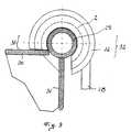
- Fig. 3 is a plan view of the sliding connection with the support guide column.
- a leader 20 is vertical in the working position. It is lifted by an arm 22 held, the free end of a rotary swivel unit 27 of the leader 20th connected is.
- the sliding connections or guide bearings 1 are on a support guide column 29, which is part of the leader 20, pushed on. Using holding arms 28, the guide bearings 1 are rigidly connected to a pile driver 21.
- a Foundation device 24 to be driven is vertical under the ram bear 21 set up on the ground 25 and a Schiaghaube 23 of the ramming 21 on the top free end of the foundation 24 placed.
- the guide unit 26 is by means of this guide bearing 1 with a support guide column 29 of leader 20 connected.
- the inner diameter (di) of the outer hollow cylinder 16 and the outer diameter (da) of the inner hollow cylinder 2 is slight Game; the inner surface of rotation 5 of the inner hollow cylinder 2 is as Slide surface formed.
- the inner rotating surface 5 of the inner hollow cylinder 2 includes the support guide column 29 with play.
- the length of the chord 6 on the inside diameter (di) of the inner hollow cylinder 2 is less than the diameter of the Support guide pillar.
- the end faces of the inner hollow cylinder 2 are as outer flanges 7 and are located on the end faces 8 of the outer hollow cylinder 16 with game on.
- the guide bearing 1 points, uniformly parallel to its longitudinal central axis 17, in its basic form a circular sector-like recess 10.
- the two close the cut surfaces of the circular sector-like recess 10 forming legs 11, 12 an angle of 90 °.
- the crossing point of this Legs 11, 12 lie on the side having the sector-like recess 10, outside the center of the guide bearing 1.
- the wall thickness of the outer Hollow cylinder 16 must be less than the length of the chord 6 on the inner diameter (di) of the inner hollow cylinder 2 to allow intermeshing.
- the support guide column 29 is part of leader 20, with at least two parallel opposing plates 30 parallel from the corner column axes inwards against the Middle of leader 20 are arranged shifted.
- the other two plates 31 can be welded to the center of the support guide column 29.
- the battering bear 21 is arranged via holding arms 28 which are arranged on the outer hollow cylinder are connected to the leader 20.
- the inner hollow cylinder 2 should therefore encompass the support guide column 29 with preferably 260 °.
- the chord 13 on the inner diameter of the outer steel cylinder 16 must be larger than the distances a, b. These distances result from the legs 11, 12 and the associated parallel tangents on the outer circumference of the inner hollow cylinder 2.
Landscapes
- Engineering & Computer Science (AREA)
- Life Sciences & Earth Sciences (AREA)
- General Life Sciences & Earth Sciences (AREA)
- Mining & Mineral Resources (AREA)
- Paleontology (AREA)
- Civil Engineering (AREA)
- General Engineering & Computer Science (AREA)
- Structural Engineering (AREA)
- Placing Or Removing Of Piles Or Sheet Piles, Or Accessories Thereof (AREA)
- Earth Drilling (AREA)
Description
Darüber hinaus muß zur einfachen Trennung der beiden Hohlzylinder im von der Trag-Führungssaule 29 abgezogenen Zustand, die Sehne 13 am Innendurchmesser des äußeren Stahlzylinders 16 größer sein als die Abstände a, b. Diese Abstände ergeben sich aus den Schenkeln 11, 12 und den dazugehörigen parallelen Tangenten am Außenumfang des inneren Hohlzylinders 2.
Claims (5)
- Mäkler mit einer Gleitverbindung für die Führung eines bewegten Gewichtes, insbesondere eines Rammbären und/oder die Führung einer mit einem Hubarm, vorzugsweise über eine Dreh-Schwenkeinheit, verbundenen Führungseinheit mit einem Mäkler, insbesondere bei einer Einrichtung zum Rammen von Masten, Piloten, Fundierungen oder dgl., wobei der Mäkler rechteckigen oder quadratischen Querschnitt aufweist, und aus vier rechtwinkelig zueinander angeordneten Platten oder dgl. besteht, dessen Kanten aus vier, kreisrunden Querschnitt aufweisenden Trag-Führungssäulen gebildet sind, dadurch gekennzeichnet, daß mindestens zwei gegenüberliegende Platten (30) des Mäklers (20) parallel aus den Ecksäulenachsen nach innen gegen die Mittellinie des Mäklers (20) verschoben angeordnet sind, daß zwei ineinander angeordnete koaxiale Hohlzylinder (2 bzw. 16) vorgesehen sind, wobei der äußere Hohlzylinder (16) mit dem Gewicht (21) bzw. der Führungseinheit (26) verbunden ist und der innere Hohlzylinder (2) die Trag-Führungssäule (29) mehr als 180° insbesondere 260° umschließt, und die Stirnseiten des inneren Hohlzylinders (2) als Außenflansch (7) für den äußeren Hohlzylinder (16) ausgebildet sind, und daß die als Führungslager (1) auf der Trag-Führungssäule (29) und ineinander angeordneten Hohlzylinder (2, 16) eine im Querschnitt kreissektorartige Ausnehmung (10) aufweisen, wobei die Sehne (6) dieser Ausnehmung (10) am Innendurchmesser (di) des inneren Hohlzylinders (2) kleiner ist als der Durchmesser der Trag-Führungssäule (29) und die beiden die Schnittflächen der kreissektorartigen Ausnehmung (10) bildenden Schenkel (11, 12) einen rechten Winkel einschließen, und der Kreuzungspunkt dieser Schenkel (11, 12) auf der die sektorartige Ausnehmung (10) aufweisenden Seite, außerhalb des Mittelpunktes des Führungslagers (1) liegt.
- Mäkler mit einer Gleitverbindung nach Anspruch 1, dadurch gekennzeichnet, daß der innere Hohlzylinder (2) aus einem relativ weichen Werkstoff, vorzugsweise einem Lagermaterial, insbesondere aus Bronze, und der äußere Hohlzylinder (16) aus einem relativ harten Werkstoff, insbesondere aus Stahl, ausgeführt ist.
- Mäkler mit einer Gleitverbindung nach Anspruch 1 oder 2, dadurch gekennzeichnet, daß die innere (5) Rotationsfläche des inneren Hohlzylinders (2) als Gleitfläche ausgebildet ist.
- Mäkler mit einer Gleitverbindung nach einem der Ansprüche 1 bis 3, dadurch gekennzeichnet, daß zwischen dem Innendurchmesser (Di) des äußeren Hohlzylinders (16) und dem Außendurchmesser (da) des inneren Hohlzylinders (2) ein geringfügiges Spiel vorgesehen ist.
- Mäkler mit einer Gleitverbindung nach einem der Ansprüche 1 bis 4, dadurch gekennzeichnet, daß die Länge der Sehne (13) der Ausnehmung (10) am inneren Durchmesser des äußeren Hohlzylinder (16) größer ist als der Abstand (a bzw. b) zwischen den Schenkeln (11, 12) und den zu den Schenkeln (11, 12) parallel verlaufenden Tangenten am äußeren Umfang des inneren Hohlzylinders (2).
Applications Claiming Priority (3)
| Application Number | Priority Date | Filing Date | Title |
|---|---|---|---|
| AT1343/94 | 1994-07-07 | ||
| AT0134394A AT400732B (de) | 1994-07-07 | 1994-07-07 | Gleitverbindung |
| PCT/AT1995/000127 WO1996001928A1 (de) | 1994-07-07 | 1995-06-22 | Gleitverbindung |
Publications (2)
| Publication Number | Publication Date |
|---|---|
| EP0769086A1 EP0769086A1 (de) | 1997-04-23 |
| EP0769086B1 true EP0769086B1 (de) | 1998-08-19 |
Family
ID=3511855
Family Applications (1)
| Application Number | Title | Priority Date | Filing Date |
|---|---|---|---|
| EP95921647A Expired - Lifetime EP0769086B1 (de) | 1994-07-07 | 1995-06-22 | Mäkler mit einer gleitverbindung |
Country Status (6)
| Country | Link |
|---|---|
| EP (1) | EP0769086B1 (de) |
| AT (1) | AT400732B (de) |
| AU (1) | AU2664695A (de) |
| DE (1) | DE59503284D1 (de) |
| FI (1) | FI970008A0 (de) |
| WO (1) | WO1996001928A1 (de) |
Family Cites Families (3)
| Publication number | Priority date | Publication date | Assignee | Title |
|---|---|---|---|---|
| SE399927B (sv) * | 1972-08-10 | 1978-03-06 | Goeteborgs Betonpalar | Palkran |
| US4050526A (en) * | 1975-05-07 | 1977-09-27 | Foresight Industries | Post driving machine |
| AT398323B (de) * | 1992-06-10 | 1994-11-25 | Elin Energieversorgung | Einrichtung zum rammen einer fundierung vorzugsweise für einen mast |
-
1994
- 1994-07-07 AT AT0134394A patent/AT400732B/de not_active IP Right Cessation
-
1995
- 1995-06-22 AU AU26646/95A patent/AU2664695A/en not_active Abandoned
- 1995-06-22 DE DE59503284T patent/DE59503284D1/de not_active Expired - Lifetime
- 1995-06-22 EP EP95921647A patent/EP0769086B1/de not_active Expired - Lifetime
- 1995-06-22 WO PCT/AT1995/000127 patent/WO1996001928A1/de not_active Ceased
-
1997
- 1997-01-02 FI FI970008A patent/FI970008A0/fi not_active Application Discontinuation
Also Published As
| Publication number | Publication date |
|---|---|
| AT400732B (de) | 1996-03-25 |
| DE59503284D1 (de) | 1998-09-24 |
| FI970008A7 (fi) | 1997-01-02 |
| WO1996001928A1 (de) | 1996-01-25 |
| FI970008A0 (fi) | 1997-01-02 |
| AU2664695A (en) | 1996-02-09 |
| ATA134394A (de) | 1995-07-15 |
| EP0769086A1 (de) | 1997-04-23 |
Similar Documents
| Publication | Publication Date | Title |
|---|---|---|
| DE69207997T2 (de) | Lösbare Verbindungsvorrichtung für metallische Gerüstelemente | |
| DE3145882C2 (de) | Verfahren zum Herstellen eines Fundaments für einen Mast od.dgl. | |
| EP2910699B1 (de) | Kantenprofilelementanordnung | |
| DE2305330A1 (de) | System zum aufbau von raeumlichen gebilden | |
| DE2063543A1 (de) | Fernmeldeantenne | |
| AT400732B (de) | Gleitverbindung | |
| DE2913959A1 (de) | Vorgefertigtes, als grundelement fuer die herstellung von waenden dienendes bauelement | |
| DE1481809A1 (de) | Vorrichtung zum Aufrichten und Umlegen von Masten oder Gittermasten,anwendbar insbesondere bei Kraenen und Hebezeugen | |
| DE202008017065U1 (de) | Verbindungsvorrichtung | |
| AT523623B1 (de) | Modulares System zum Bau, zur Führung und zur Befestigung von Elementen rohrförmiger Strukturen und entsprechende rohrförmige Struktur | |
| DE2812974A1 (de) | Verschalungseinheit fuer schalungen zur verwendung fuer die errichtung von bauwerken | |
| DE3302516C2 (de) | Stationäre Betonverteilereinrichtung mit einem Turm aus mehreren stumpf aufeinandergesetzten Rohrstücken | |
| DE3902290C2 (de) | Messestand zur Vorführung von Bauelementen, insbesondere von Toren | |
| DE1603624A1 (de) | Bauspielzeug mit plattenfoermigen Bauelementen | |
| DE202015105834U1 (de) | Vorrichtung zur Verbindung eines Masts mit einem Mastsockel | |
| DE2507903A1 (de) | Rammpfahl, bestehend aus rammschaft und pfahlschuh mit verdraengerteil | |
| DE2915276C3 (de) | Verbindung für Flächenkonstruktionselemente | |
| Hamann | In Gammarus pulex lebende Cysticerkoiden | |
| DE4445165A1 (de) | Vorrichtung und Verfahren zum Errichten von Gittermasten | |
| AT403183B (de) | Schalungstafel | |
| DE3520420A1 (de) | Verfahren zum bau eines brueckenbogens | |
| DE6921153U (de) | Saeulenschalung | |
| DE202024104280U1 (de) | Eine Hebebühne für Hebezeuge | |
| DE102004048365A1 (de) | Mast | |
| DE102005032363B4 (de) | Mastfundament für einen Mast |
Legal Events
| Date | Code | Title | Description |
|---|---|---|---|
| PUAI | Public reference made under article 153(3) epc to a published international application that has entered the european phase |
Free format text: ORIGINAL CODE: 0009012 |
|
| 17P | Request for examination filed |
Effective date: 19961114 |
|
| AK | Designated contracting states |
Kind code of ref document: A1 Designated state(s): DE IT |
|
| 17Q | First examination report despatched |
Effective date: 19970522 |
|
| GRAG | Despatch of communication of intention to grant |
Free format text: ORIGINAL CODE: EPIDOS AGRA |
|
| GRAG | Despatch of communication of intention to grant |
Free format text: ORIGINAL CODE: EPIDOS AGRA |
|
| GRAH | Despatch of communication of intention to grant a patent |
Free format text: ORIGINAL CODE: EPIDOS IGRA |
|
| GRAH | Despatch of communication of intention to grant a patent |
Free format text: ORIGINAL CODE: EPIDOS IGRA |
|
| GRAA | (expected) grant |
Free format text: ORIGINAL CODE: 0009210 |
|
| AK | Designated contracting states |
Kind code of ref document: B1 Designated state(s): DE IT |
|
| ITF | It: translation for a ep patent filed | ||
| REF | Corresponds to: |
Ref document number: 59503284 Country of ref document: DE Date of ref document: 19980924 |
|
| PLBE | No opposition filed within time limit |
Free format text: ORIGINAL CODE: 0009261 |
|
| STAA | Information on the status of an ep patent application or granted ep patent |
Free format text: STATUS: NO OPPOSITION FILED WITHIN TIME LIMIT |
|
| 26N | No opposition filed | ||
| PG25 | Lapsed in a contracting state [announced via postgrant information from national office to epo] |
Ref country code: IT Free format text: LAPSE BECAUSE OF NON-PAYMENT OF DUE FEES;WARNING: LAPSES OF ITALIAN PATENTS WITH EFFECTIVE DATE BEFORE 2007 MAY HAVE OCCURRED AT ANY TIME BEFORE 2007. THE CORRECT EFFECTIVE DATE MAY BE DIFFERENT FROM THE ONE RECORDED. Effective date: 20050622 |
|
| REG | Reference to a national code |
Ref country code: DE Ref legal event code: R082 Ref document number: 59503284 Country of ref document: DE Representative=s name: PATENTANWAELTE HENKEL, BREUER & PARTNER, DE |
|
| PGFP | Annual fee paid to national office [announced via postgrant information from national office to epo] |
Ref country code: DE Payment date: 20140619 Year of fee payment: 20 |
|
| REG | Reference to a national code |
Ref country code: DE Ref legal event code: R071 Ref document number: 59503284 Country of ref document: DE |