EP0768477B1 - Vorrichtung zur Uebertragung linearer Bewegungen - Google Patents
Vorrichtung zur Uebertragung linearer Bewegungen Download PDFInfo
- Publication number
- EP0768477B1 EP0768477B1 EP96116349A EP96116349A EP0768477B1 EP 0768477 B1 EP0768477 B1 EP 0768477B1 EP 96116349 A EP96116349 A EP 96116349A EP 96116349 A EP96116349 A EP 96116349A EP 0768477 B1 EP0768477 B1 EP 0768477B1
- Authority
- EP
- European Patent Office
- Prior art keywords
- casing
- toothed rail
- portions
- plate portions
- side plate
- Prior art date
- Legal status (The legal status is an assumption and is not a legal conclusion. Google has not performed a legal analysis and makes no representation as to the accuracy of the status listed.)
- Expired - Lifetime
Links
Images
Classifications
-
- F—MECHANICAL ENGINEERING; LIGHTING; HEATING; WEAPONS; BLASTING
- F16—ENGINEERING ELEMENTS AND UNITS; GENERAL MEASURES FOR PRODUCING AND MAINTAINING EFFECTIVE FUNCTIONING OF MACHINES OR INSTALLATIONS; THERMAL INSULATION IN GENERAL
- F16H—GEARING
- F16H25/00—Gearings comprising primarily only cams, cam-followers and screw-and-nut mechanisms
- F16H25/02—Gearings comprising primarily only cams, cam-followers and screw-and-nut mechanisms the movements of two or more independently moving members being combined into a single movement
-
- F—MECHANICAL ENGINEERING; LIGHTING; HEATING; WEAPONS; BLASTING
- F16—ENGINEERING ELEMENTS AND UNITS; GENERAL MEASURES FOR PRODUCING AND MAINTAINING EFFECTIVE FUNCTIONING OF MACHINES OR INSTALLATIONS; THERMAL INSULATION IN GENERAL
- F16H—GEARING
- F16H19/00—Gearings comprising essentially only toothed gears or friction members and not capable of conveying indefinitely-continuing rotary motion
- F16H19/02—Gearings comprising essentially only toothed gears or friction members and not capable of conveying indefinitely-continuing rotary motion for interconverting rotary or oscillating motion and reciprocating motion
- F16H19/04—Gearings comprising essentially only toothed gears or friction members and not capable of conveying indefinitely-continuing rotary motion for interconverting rotary or oscillating motion and reciprocating motion comprising a rack
- F16H19/043—Gearings comprising essentially only toothed gears or friction members and not capable of conveying indefinitely-continuing rotary motion for interconverting rotary or oscillating motion and reciprocating motion comprising a rack for converting reciprocating movement in a continuous rotary movement or vice versa, e.g. by opposite racks engaging intermittently for a part of the stroke
-
- F—MECHANICAL ENGINEERING; LIGHTING; HEATING; WEAPONS; BLASTING
- F16—ENGINEERING ELEMENTS AND UNITS; GENERAL MEASURES FOR PRODUCING AND MAINTAINING EFFECTIVE FUNCTIONING OF MACHINES OR INSTALLATIONS; THERMAL INSULATION IN GENERAL
- F16H—GEARING
- F16H25/00—Gearings comprising primarily only cams, cam-followers and screw-and-nut mechanisms
- F16H25/08—Gearings comprising primarily only cams, cam-followers and screw-and-nut mechanisms for interconverting rotary motion and reciprocating motion
-
- Y—GENERAL TAGGING OF NEW TECHNOLOGICAL DEVELOPMENTS; GENERAL TAGGING OF CROSS-SECTIONAL TECHNOLOGIES SPANNING OVER SEVERAL SECTIONS OF THE IPC; TECHNICAL SUBJECTS COVERED BY FORMER USPC CROSS-REFERENCE ART COLLECTIONS [XRACs] AND DIGESTS
- Y10—TECHNICAL SUBJECTS COVERED BY FORMER USPC
- Y10T—TECHNICAL SUBJECTS COVERED BY FORMER US CLASSIFICATION
- Y10T74/00—Machine element or mechanism
- Y10T74/15—Intermittent grip type mechanical movement
- Y10T74/1503—Rotary to intermittent unidirectional motion
- Y10T74/1508—Rotary crank or eccentric drive
Definitions
- the present invention relates to a linear motion apparatus which linearly moves by converting an input of rotary motion into linear motion, and more particularly to a linear motion apparatus which utilizes swinging plates and a toothed rail which forms a substantially rectilinear track.
- linear motion apparatuses for converting rotary motion into linear motion are used extensively.
- these linear motion apparatuses there is a type in which the apparatus linearly moves in the direction of an input shaft of rotation and another type in which the apparatus linearly moves in a direction perpendicular to the input shaft of rotation.
- a compact and lightweight apparatus of simple construction is used to respond to the requirement for the compact size of the overall machine.
- one which linearly moves in the direction of the input shaft of rotation by means of a ball screw is known as having high feeding accuracy in linear advancement and being capable of withstanding a high load.
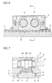
- Figs. 6 and 7 show apparatuses on which improvements have been made with respect to the assembling efficiency and motion characteristics among linear motion apparatus of this type.
- Fig. 6 is a front cross-sectional view thereof
- Fig. 7 is a cross-sectional view taken along line B 2 - B 2 of Fig. 6.
- this linear motion apparatus is provided with a toothed rail 10 serving as both a passive rack and a guide rail and a linearly driving mechanism section 20 which undergoes linear motion relative to the same.
- the toothed rail 10 has a plurality of teeth 11 and a plurality of bolt holes 12 for fixing the rail 10 to an unillustrated supporting member.
- the linearly driving mechanism section 20 has a casing 21 and a plurality of swinging plates 22A, 22B, and 22C accommodated in the casing 21 and meshing with the teeth 11 of the toothed rail 10, and teeth 23 of the swinging plates 22A to 22C have a tooth profile of an identical pitch to that of the teeth 11 of the toothed rail 10.
- swinging plates 22A to 22C are supported in the casing 21 through crankshafts 24 and 25, one crankshaft 24 serves as an input shaft which is driven by an unillustrated drive motor.
- the arrangement provided is such that when the crankshaft 24 is rotated by an input, the swinging plates 22A to 22C supported by the crankshafts 24 and 25 mesh with the teeth 11 of the toothed rail 10 while undergoing circular motion (hereafter, this state of motion will be simply referred to as swinging motion) in parallel to each other while maintaining a predetermined phase difference within the casing 21, thereby causing the casing 21 and the toothed rail 10 to undergo relative movement in the longitudinal direction of the toothed rail 10.
- Reference numerals 31 and 32 denote casing guiding means for guiding the casing 21 relatively movably with respect to the toothed rail 10 on both sides, in a tooth width direction, of the toothed rail 10. These casing guiding means 31 and 32 are adapted to guide the casing 21 only in the longitudinal direction (axial direction) of the toothed rail 10.
- the guiding means 31 has a guide groove portion 33 formed on one side surface of the toothed rail 10, a ball circulating portion 34 provided in one side plate portion of the casing 21, and a plurality of circulating-type balls 35 fitted in the guide groove portion 33 and the ball circulating portion 34.
- the guiding means 32 similarly has a guide groove portion 37 formed on the other side surface of the toothed rail 10, a ball circulating portion 38 provided in the other side plate portion of the casing 21, and a plurality of circulating-type balls 39 fitted in the guide groove portion 37 and the ball circulating portion 38.
- one of the swinging plates 22A to 22C moves to a spaced-apart position which is spaced apart most from a central axis of the toothed rail 10 while maintaining a phase difference with the other swinging plates 22B and 22C to a fixed level within a certain range of swinging motion (e.g., in a range from 0 degree to 180 degrees) and causes its teeth 23 to abut against apices of the teeth 11, then approaches the central axis of the toothed rail 10 while pushing one inclined surfaces of the teeth 11, further approaches the central axis of the toothed rail 10, and reaches the troughs at the dedenda of the teeth 11.
- a certain range of swinging motion e.g., in a range from 0 degree to 180 degrees
- the casing 21 undergoes relative movement in the longitudinal direction of the toothed rail 10 only by one pitch of the teeth 11 per revolution of the crankshafts 24 and 25, so that a moving portion on which the casing 21 is attached slowly moves at a predetermined speed.
- This mechanism comprises a passive rack with a plurality of teeth, a plurality of active racks respectively having a plurality of teeth having the same pitch as that of the teeth of the passive rack and meshing with the passive rack.
- a plurality of rotatable crankshafts respectively having eccentric circular portions different in phase from one another are provided which respectively have the active rack supported on the eccentric circular portions in such a manner that the passive rack is moved in its longitudinal direction through the active racks by rotary motions of the plurality of rotatable crankshafts.
- a casing is provided which may include lateral bottom portions formed with ball circulation passageways.
- the pair of side plate portions which are provided on both sides, in the tooth width direction, of the toothed rail and are guided by the guiding means are coupled to each other and are reinforced at their opposite end portions and intermediate portions by means of the pair of end plate portions located on opposite sides of the swinging plates and the coupling member located between the plurality of crankshafts as viewed in the longitudinal direction of the toothed rail.
- each of the swinging plates has a through hole portion through which the coupling member of the casing is passed through, and the coupling member of the casing is detachably connected to the side plate portions of the casing, the coupling member can be disposed at a position effective for the reinforcement of the casing, and the operation of assembling the apparatus can be facilitated.
- the assembling efficiency is further improved if the aforementioned casing is comprised of first and second segments which vertically oppose each other with the plurality of crankshafts placed therebetween and which are coupled to each other and constitute the side plate portions and the end plate portions, and if the aforementioned coupling member couples those portions of the toothed rail-side second segment (of the first and second segments) which constitute the lower portions of the side plate portions.
- the guiding means is preferably provided with guide grooves formed on both side surfaces, in the tooth width direction, of the toothed rail, as well as rolling members (e.g., balls or rollers) which are interposed between each of the side plate portions of the casing and the toothed rail and are held in the side plate portions so as to roll along the guide grooves.
- rolling members e.g., balls or rollers
- Figs. 1 to 5 are diagrams illustrating an example of a preferred embodiment of the present invention.
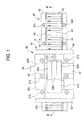
- Fig. 1 is a plan view thereof;
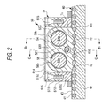
- Fig. 2 is a cross-sectional view taken along line A A in Fig. 1;
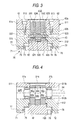
- Fig. 3 is a cross-sectional view taken along line B 1 B 1 in Fig. 2;
- Fig. 4 is a cross-sectional view taken along line C C in Fig. 2;
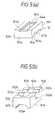
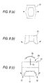
- Figs. 5(a) and 5(b) are perspective views of segments constituting a casing, respectively.
- this linear motion apparatus is comprised of: a toothed rail 40 having a plurality of teeth T 1 of a predetermined pitch and forming a linear track; a linearly driving mechanism section 50 provided along the toothed rail 40 in such a manner as to move relative to the same; and a guiding means 70 for guiding a casing 51 of the linearly driving mechanism section 50 on both sides, in the tooth width direction, of the toothed rail 40 such that the casing 51 of the linearly driving mechanism section 50 is capable of moving relative to the toothed rail 40.
- the toothed rail 40 is comprised of, for instance, a plurality of cylindrical pins 41 arranged in parallel at predetermined pitches in such a manner as to form the teeth T 1 ; a rail main body 42 having a plurality of parallel semicircular grooves 42a for holding the pins 41 rotatably about their axes and a plurality of fixing bolt holes 42b; and a pair of holding plates 43 having an L-shaped cross section and engaging opposite ends of the pins 41 so as to restrict the movement of the pins 41 other than their rotation within the semicircular grooves 42a.
- a lubricant in the case of a heavy load, it is preferable to apply a lubricant to the peripheries of the pins 41, but in a case where the linear motion apparatus is used for a small lightweight load, it is possible to form lubricating coats on the outer peripheries of the pins 41 or the semicircular grooves 42a of the rail main body 42, or form the pins 41 by a material having high self-lubricity.
- the linearly driving mechanism section 50 is comprised of the casing 51 having a plurality of shaft holes 52L and 52R arranged on parallel axes; a plurality of swinging plates 53A, 53B, and 53C having a plurality of teeth T 2 of the same pitch as that of the teeth T 1 of the toothed rail 40; and a plurality of rotatable crankshafts 54 and 55 which engage and support the swinging plates 53A to 53C such that the teeth T 2 of the swinging plates 53A to 53C swing with predetermined amounts of eccentricity in parallel to each other while maintaining a predetermined phase difference among them.
- the swinging plates 53A to 53C are accommodated in, for instance, the casing 51, and are supported in parallel to each other in such a manner as to cause the teeth T 1 to oppose the toothed rail 40 through the crankshafts 54 and 55 by means of the casing 51.
- the teeth T 2 of the swinging plates 53A to 53C have a tooth profile of, for instance, a trochoidal curve or a cycloidal curve.
- the swinging plates 53A to 53C are respectively supported by the crankshafts 54 and 55 through needle bearings 56a, 56b, and 56c, and the two crankshafts 54 and 55 are supported by the casing 51 through a pair of bearings 57a and 57b.
- a large-diameter hole is formed in a swinging plate 53 disposed in the center among the swinging plates 53A to 53C, and smaller-diameter holes are respectively formed in remaining swinging plates 52 and 54.
- a central eccentric cam portion 54b among eccentric cam portions 54a, 54b, and 54c of one crankshaft 54 is formed with a larger diameter than the remaining eccentric cam portions 54a and 54c on both sides, while a central eccentric cam portion 55b of the other crankshaft 55 is similarly formed with a larger diameter than the eccentric cam portions on both sides (not shown).
- this linearly driving mechanism section 50 When one crankshaft 54 is rotated by the power from an external circuit, this linearly driving mechanism section 50 causes the swinging plates 53A to 53C constituting a parallel link together with the crankshafts 54 and 55 to undergo circular motion (swinging motion) in parallel with each other while maintaining a predetermined phase difference, and causes the casing 51 and the toothed rail 40 to undergo relative movement in the direction of the central axis of the toothed rail 40. That is, the linearly driving mechanism section 50 functions as a motion converting mechanism which converts the rotation inputted to the crankshaft 54 to the relative movement of the casing 51 and the toothed rail 40 in a predetermined rectilinear direction by means of the crankshafts 54 and 55 and the swinging plates 53A to 53C.
- the casing 51 has a pair of side plate portions 61 and 62 which extend in parallel on both sides, in the tooth width direction, of the toothed rail 40, as well as a pair of end plate portions 63 and 64 which are located on opposite sides, as viewed in the longitudinal direction of the toothed rail 40, of the swinging plates 53A to 53C and connect opposite end portions of the pair of side plate portions 61 and 62.
- the casing 51 is constructed such that it is split into first and second segments 511 and 512, which are a vertical pair of substantially rectangular frame members, and the segments are coupled to each other by a plurality of bolts 513, so as to allow the crankshafts 54 and 55 to be rotatably supported through the bearings 57a and 57b in a state in which the plurality of swinging plates 53A to 53C are fitted to the crankshafts 54 and 55 through the needle bearings 56a, 56b, and 56c.
- upper halves of the side plate portions 61 and 62 and the end plate portions 63 and 64 are formed by the first segment 511
- lower halves of the side plate portions 61 and 62 and the end plate portions 63 and 64 are formed by the second segment 512.
- the guiding means 70 is comprised of casing-side guide groove portions 71 and 72 which are respectively provided on inner sides of those portions of the second segment 512 of the casing 51 that constitute portions of the side plate portions 61 and 62, i.e., lower halves of the pair of side plate portions 61 and 62 of the casing 51; rail-side guide groove portions 73 and 74 which are respectively provided on both side surfaces of the toothed rail 40 in such a manner as to extend in the longitudinal direction of the toothed rail 40 while maintaining a high degree of parallelism with respect to the central axis of the toothed rail 40; a plurality of balls 75 and 76 (rolling members which may be rollers which are not spherical) which are rollably provided in passages formed by the guide groove portions 71 to 74; and circulating passage portions 77 and 78 which are respectively formed in the lower halves of the side plate portions 61 and 62 of the casing 51 and, together with the aforementioned passages, form loop-like ball circulating passage
- groove portions respectively having a substantially V-shaped cross section are illustrated as the casing-side groove portions 71 and 72 and the rail-side guide groove portions 73 and 74, these grooves may be provided with semicircular cross sections, and the circulating passage portions 77 and 78 may be correspondingly formed as holes having circular cross sections.
- the balls 75 and 76 pass between the casing-side guide groove portion 71 and the rail-side guide groove portion 73 and between the casing-side guide groove portion 72 and the rail-side guide groove portion 74, respectively, while being circulated through the circulating passage 77 and 78, respectively, the balls 75 and 76 are adapted to guide the casing 51 relatively movably in the X direction in Fig.
- This guiding means 70 guides the casing 51 and the toothed rail 40 relatively movably in a predetermined axial direction through the aforementioned balls 75 and 76, and restricts the relative movement and rotation of these two members in a direction other than the aforementioned predetermined axial direction.
- portions 61a and 62a which constitute upper portions of the side plate portions 61 and 62 are each provided a pair of semicircular groove portions 511a and 511b which form peripheral wall surfaces of half circumferences of the pair of shaft holes 52L and 52R.
- portions 61b and 62b which constitute lower portions of the side plate portions 61 and 62 are each provided with a pair of semicircular groove portions 512a and 512b which form peripheral wall surfaces of the remaining half circumferences of the pair of shaft holes 52L and 52R.
- accommodating hole portions 511c and 512c with rectangular cross sections for accommodating the swinging plates 53A to 53C are respectively formed in central portions of the first and second segments 511 and 512.
- a recessed portion 511d is formed in an upper portion of the first segment 511 in such a manner as to close the accommodating hole 511c of the first segment 511, and a cover 514 is fitted therein.
- a pair of coaxial round holes 512d are respectively formed in the portions 61b and 62b which form the lower portions of the pair of side plate portions 61 and 62.
- recessed portions 512e opposing the tooth face portions of the toothed rail 40 are respectively formed in portions 63b and 64b which constitute lower halves of the pair of end plate portions 63 and 64 of the second segment 512.
- the casing 51 of this embodiment is further provided with a coupling member 521, which is located between the plurality of crankshafts 54 and 55 as viewed in the longitudinal direction of the toothed rail 40 and couple intermediate portions of the pair of side plate portions 61 and 62. As shown in Fig.
- the coupling member 521 of the casing 51 is passed through through-hole portions 531, 532, and 533 formed at predetermined positions in the swinging plates 53A to 53C, and is detachably connected to the portions 61b and 62b constituting the lower portions of the side plate portions 61 and 62 of the second segment 512 at its opposite end portions to which a plurality of bolts are screwed, as shown in Fig. 3.
- the diameters and positions of the respective through hole portions 531, 532, and 533 in the swinging plates 53A to 53C are set such that the swinging plates 53A to 53C and the coupling member 521 do not abut against each other and are spaced apart a predetermined distance in a state in which the swinging plates 53A to 53C are supported by the crankshafts 54 and 55.
- the coupling member 521 is inserted in advance in the through hole portions 531, 532, and 533 in the swinging plates 53A to 53C with the crankshafts 54 and 55 fitted thereto, and the bolts 522 and 523 which are respectively inserted in the pair of round holes 512d are screwed into its opposite end portions so as to couple the intermediate portions of the side plate portions 61 and 62.
- the side plate portions 61 and 62 of the casing 51 are coupled to each other at their opposite ends by means of the end plate portions 63 and 64, and since the side plate portions 61 and 62 at substantially intermediate positions of their portions for supporting the crankshafts 54 and 55 are coupled to each other and are reinforced, even if the casing 51 is compact, the casing 51 is prevented from becoming expanded in the vicinities of the portions for supporting the crankshafts, i.e., in the vicinities of intermediate portions of the side plate portions 61 and 62, as has been experienced in the past. In addition, it is possible to suppress deflections which cause a widening of an interval between the lower end portions of the casing-side guide groove portions 71 and 72 which are constructed in a downwardly-oriented cantilevered manner.
- the pair of side plate portions 61 and 62 which are disposed on both sides, in the tooth width direction, of the toothed rail 40 and are guided by the guiding means 70, are coupled to each other and are reinforced at their opposite end portions and their intermediate portions by means of the pair of end plate portions 63 and 64 located on opposite sides of the swinging plates 53A to 53C as well as the coupling member 521 located between the crankshafts 54 and 55 as viewed in the longitudinal direction of the toothed rail 40. Therefore, the guiding means 70 is capable of providing stable guiding operation.
- the swinging plates 53A to 53C are respectively provided with the through hole portions 531 to 533 through which the coupling member 521 of the casing 51 is passed, and the coupling member 521 of the casing 51 is detachably connected to the side plate portions 61 and 62 of the casing 51, the coupling member 521 can be disposed at a position effective for the reinforcement of the casing 51, and the operation of assembling the apparatus can be facilitated.
- the assembling efficiency is further improved since the casing 51 is comprised of the first and second segments 511 and 512 with the plurality of crankshafts 54 and 55 placed therebetween and which constitute the side plate portions 61 and 62 and the end plate portions 63 and 64, and since the coupling member 521 couples those portions of the toothed rail 40-side second segment 512 (of the first and second segments 511 and 512) which constitute the lower portions of the side plate portions 61 and 62.
- the casing includes: a pair of side plate portions which extend in parallel on both sides, in the tooth width direction, of the toothed rail and are guided by the guiding means; a pair of end plate portions which are located on opposite sides, as viewed in a longitudinal direction of the toothed rail, of the swinging plates and connect opposite end portions of the pair of side plate portions; and a coupling member which is located between the plurality of crankshafts as viewed in the longitudinal direction of the toothed rail and couple intermediate portions of the pair of side plate portions.
- the pair of side plate portions can be coupled to each other and reinforced at their opposite end portions and intermediate portions by means of the pair of end plate portions located on opposite sides of the swinging plates and the coupling member located between the plurality of crankshafts.
- each of the swinging plates has a through hole portion through which the coupling member of the casing is passed through, and the coupling member is detachably connected to the side plate portions of the casing, the coupling member can be disposed at a position effective for the reinforcement of the casing, and the operation of assembling the apparatus can be facilitated.
Landscapes
- Engineering & Computer Science (AREA)
- General Engineering & Computer Science (AREA)
- Mechanical Engineering (AREA)
- Transmission Devices (AREA)
- Machine Tool Units (AREA)
Claims (4)
- Linearbewegungsvorrichtung mit:einer gezahnten Schiene (40) mit einer Vielzahl von Zähnen T1 eines vorbestimmten Abstandes,einem linearen Antriebsmechanismusbereich (50), welcher eine Vielzahl von Schwingplatten (53) mit einer Vielzahl von Zähnen (T2)von im wesentlichen gleichen Abstand wie die Zähne (T1) der gezahnten Schiene (40), eine Vielzahl von drehbaren Kurbelwellen (54, 55), welche mit den Schwingplatten (53) so in Eingriff sind, daß die Zähne der Schwingplatten parallel zueinander unter Beibe haltung einer vorbestimmten Phasendifferenz schwingen, und ein Gehäuse (51) zur Lagerung der Schwingplatten (53) durch die Kurbelwellen (54, 55) aufweist, wobei die Schwingplatten gegenüberliegend zur gezahnten Schiene (40) parallel zueinander angeordnet sind und wobei der lineare Antriebsmechanismusbereich (50) die Drehung der Kurbelwelle in eine Relativbewegung von Gehäuse (51) und gezahnter Schiene (40) umwandelt, undeiner Führungseinrichtung zur Führung des Gehäuses (51) auf beiden Seiten in Zahnbreitenrichtung der gezahnten Schiene (40), wobei das Gehäuse eine Relativbewegung bezüglich der gezahnten Schiene durchführen kann und wobei das Gehäuse (51) ein Paar von Seitenplattenbereichen (61, 62) aufweist, weiche parallel auf beiden Seiten in Zahnbreitenrichtung der gezahnten Schiene (40) sich erstrecken und durch die Führungseinrichtung geführt sind, gekennzeichnet durch ein Paar von Endplattenbereichen (63, 64), die auf gegenüberliegenden Seiten gesehen in Längsrichtung der gezahnten Schiene (40) der Schwingplatten (53) angeordnet sind und gegenüberliegende Endbereiche des Paares von Seitenplattenbereichen (61, 62) verbinden, wobei ein Kopplungsbauteil (521) zwischen der Vielzahl von Kurbelwellen (54, 55) ge sehen in Längsrichtung der gezahnten Schiene (40) angeordnet ist und Zwi schenbereiche des Paares von Seitenplattenbereichen (61, 62) verbindet.
- Linearbewegungsvorrichtung nach Anspruch 1, dadurch gekennzeichnet, daß jede der Schwingplatten (53) einen Durchgangsbohrungsbereich (531, 532, 533) aufweist, durch welchen das Kopplungsbauteil (521) des Gehäuses (51) hindurchtritt, und daß das Kopplungsbauteil des Gehäuses lösbar mit den Seitenplattenbereichen (61, 62) des Gehäuses (51) verbunden ist.
- Linearbewegungsvorrichtung nach Anspruch 1, dadurch gekennzeichnet, daß das Gehäuse (51) erste und zweite Segmente (511, 512) aufweist, die vertikal gegenüberliegend mit den Kurbelwellen (54, 55) dazwischen angeordnet sind und welche miteinander verbunden sind und die Seitenplattenbereiche (61, 62) und Endplattenbereiche (63, 64) bilden, wobei das Kopplungsbauteil (521) jene Bereiche des zweiten Segments (512) verbindet, welche die unteren Bereiche der Seitenplattenbereiche (61, 62) bilden.
- Linearbewegungsvorrichtung nach Anspruch 1, dadurch gekennzeichnet, daß die Führungseinrichtung (70) Führungsnuten (71, 73; 72, 74; 77; 78) auf beiden Seitenflächen in Zahnbreitenrichtung der gezahnten Schienen (40) und Rollbauteile (75, 76) aufweist, die zwischen jedem der Seitenplattenbereichen (61, 62) des Gehäuses (51) und der gezahnten Schiene (40) angeordnet und so in den Seitenplattenbereichen gehalten sind, daß sie entlang der Führungsnut (71, 73; 72, 74; 77; 78) abrollen.
Applications Claiming Priority (2)
| Application Number | Priority Date | Filing Date | Title |
|---|---|---|---|
| JP7263777A JPH09105446A (ja) | 1995-10-12 | 1995-10-12 | 直進運動装置 |
| JP263777/95 | 1995-10-12 |
Publications (2)
| Publication Number | Publication Date |
|---|---|
| EP0768477A1 EP0768477A1 (de) | 1997-04-16 |
| EP0768477B1 true EP0768477B1 (de) | 1999-03-17 |
Family
ID=17394142
Family Applications (1)
| Application Number | Title | Priority Date | Filing Date |
|---|---|---|---|
| EP96116349A Expired - Lifetime EP0768477B1 (de) | 1995-10-12 | 1996-10-11 | Vorrichtung zur Uebertragung linearer Bewegungen |
Country Status (4)
| Country | Link |
|---|---|
| US (1) | US5806369A (de) |
| EP (1) | EP0768477B1 (de) |
| JP (1) | JPH09105446A (de) |
| DE (1) | DE69601772T2 (de) |
Families Citing this family (7)
| Publication number | Priority date | Publication date | Assignee | Title |
|---|---|---|---|---|
| WO2000063104A1 (fr) * | 1999-04-15 | 2000-10-26 | Kabushiki Kaisha Toshiba | Dispositif transporteur |
| TW529519U (en) * | 2002-06-13 | 2003-04-21 | Ruei-Sen Liau | Apparatus for ascending and descending vertical shaft of multi-functional carpentry grinding machine |
| FR2901856B1 (fr) * | 2006-06-06 | 2009-02-06 | Bubendorff Sa | Dispositif d'entrainement en translation d'un objet |
| CN102390019A (zh) * | 2010-11-18 | 2012-03-28 | 西安合升动力科技有限公司 | 交流永磁同步电机驱动式机床工作台 |
| AT16228U1 (de) * | 2018-01-11 | 2019-04-15 | Engel Austria Gmbh | Antrieb zur Übersetzung einer rotatorischen Antriebsbewegung in eine lineare Bewegung |
| ES2928913T3 (es) * | 2019-06-04 | 2022-11-23 | Ims Gear Se & Co Kgaa | Accionamiento lineal, unidad de ajuste longitudinal de un asiento y automóvil |
| ES2980892T3 (es) * | 2021-08-03 | 2024-10-03 | Ims Gear Se & Co Kgaa | Actuador lineal, dispositivo de ajuste longitudinal para un asiento y vehículo de motor |
Family Cites Families (4)
| Publication number | Priority date | Publication date | Assignee | Title |
|---|---|---|---|---|
| EP0482827B1 (de) * | 1990-10-23 | 1994-06-08 | Teijin Seiki Company Limited | Mechanismus zum Umwandeln einer Rotationsbewegung in eine Längsbewegung |
| CA2050507C (en) * | 1990-10-26 | 1999-07-13 | Lane Jordon Abrams | Message-oriented bank controller interface |
| JPH04321857A (ja) * | 1991-04-23 | 1992-11-11 | Teijin Seiki Co Ltd | 直進運動機構 |
| JPH07280057A (ja) * | 1994-04-06 | 1995-10-27 | Teijin Seiki Co Ltd | 直進運動機構およびその作製方法並びにその作製方法を実施する加工機械 |
-
1995
- 1995-10-12 JP JP7263777A patent/JPH09105446A/ja active Pending
-
1996
- 1996-10-11 US US08/730,690 patent/US5806369A/en not_active Expired - Fee Related
- 1996-10-11 EP EP96116349A patent/EP0768477B1/de not_active Expired - Lifetime
- 1996-10-11 DE DE69601772T patent/DE69601772T2/de not_active Expired - Fee Related
Also Published As
| Publication number | Publication date |
|---|---|
| JPH09105446A (ja) | 1997-04-22 |
| EP0768477A1 (de) | 1997-04-16 |
| US5806369A (en) | 1998-09-15 |
| DE69601772D1 (de) | 1999-04-22 |
| DE69601772T2 (de) | 1999-07-08 |
Similar Documents
| Publication | Publication Date | Title |
|---|---|---|
| KR890002294B1 (ko) | 직선운동 로울러 베어링 | |
| JP5031957B2 (ja) | リニアアクチュエータ | |
| EP0768477B1 (de) | Vorrichtung zur Uebertragung linearer Bewegungen | |
| EP0482827B1 (de) | Mechanismus zum Umwandeln einer Rotationsbewegung in eine Längsbewegung | |
| CN113892003B (zh) | 滚珠丝杠机构和直线移动装置 | |
| JPH10318343A (ja) | 直線運動装置 | |
| JPH03234912A (ja) | 直動転がり案内ユニット | |
| JP2527218Y2 (ja) | 直動転がり案内ユニット | |
| JPH09119496A (ja) | 直進運動装置 | |
| TWM660151U (zh) | 螺桿滑台裝置及機械手臂 | |
| JPH03270844A (ja) | スライドテーブル機構 | |
| JP2008089004A (ja) | 転がり案内装置 | |
| CN100398852C (zh) | 具有偏负载防止机构的直线导向装置 | |
| JP2005180602A (ja) | ガイド機構 | |
| JP2559974Y2 (ja) | 電動一軸アクチュエータ | |
| JP2000018356A (ja) | 直進運動装置 | |
| JP3523973B2 (ja) | ボールチェーンを用いた直線案内装置 | |
| JP3219170B2 (ja) | 直動案内軸受 | |
| JPS5833324Y2 (ja) | ボ−ルねじ装置 | |
| JPH02232133A (ja) | 直線摺動用テーブル | |
| JPS6159017A (ja) | 直線運動ロ−ラ−ベアリング | |
| JP2863529B2 (ja) | 転動ボール形変速装置 | |
| JPH04210153A (ja) | 直進運動機構 | |
| JPH11277359A (ja) | ボールねじ装置の中間サポート | |
| JPS63196341A (ja) | 送り案内機構 |
Legal Events
| Date | Code | Title | Description |
|---|---|---|---|
| PUAI | Public reference made under article 153(3) epc to a published international application that has entered the european phase |
Free format text: ORIGINAL CODE: 0009012 |
|
| AK | Designated contracting states |
Kind code of ref document: A1 Designated state(s): DE FR GB |
|
| 17P | Request for examination filed |
Effective date: 19970702 |
|
| 17Q | First examination report despatched |
Effective date: 19970806 |
|
| GRAG | Despatch of communication of intention to grant |
Free format text: ORIGINAL CODE: EPIDOS AGRA |
|
| GRAG | Despatch of communication of intention to grant |
Free format text: ORIGINAL CODE: EPIDOS AGRA |
|
| GRAG | Despatch of communication of intention to grant |
Free format text: ORIGINAL CODE: EPIDOS AGRA |
|
| GRAH | Despatch of communication of intention to grant a patent |
Free format text: ORIGINAL CODE: EPIDOS IGRA |
|
| GRAH | Despatch of communication of intention to grant a patent |
Free format text: ORIGINAL CODE: EPIDOS IGRA |
|
| GRAA | (expected) grant |
Free format text: ORIGINAL CODE: 0009210 |
|
| AK | Designated contracting states |
Kind code of ref document: B1 Designated state(s): DE FR GB |
|
| REF | Corresponds to: |
Ref document number: 69601772 Country of ref document: DE Date of ref document: 19990422 |
|
| ET | Fr: translation filed | ||
| PLBE | No opposition filed within time limit |
Free format text: ORIGINAL CODE: 0009261 |
|
| STAA | Information on the status of an ep patent application or granted ep patent |
Free format text: STATUS: NO OPPOSITION FILED WITHIN TIME LIMIT |
|
| 26N | No opposition filed | ||
| REG | Reference to a national code |
Ref country code: GB Ref legal event code: IF02 |
|
| PGFP | Annual fee paid to national office [announced via postgrant information from national office to epo] |
Ref country code: FR Payment date: 20021008 Year of fee payment: 7 |
|
| PGFP | Annual fee paid to national office [announced via postgrant information from national office to epo] |
Ref country code: GB Payment date: 20021009 Year of fee payment: 7 |
|
| PGFP | Annual fee paid to national office [announced via postgrant information from national office to epo] |
Ref country code: DE Payment date: 20021017 Year of fee payment: 7 |
|
| PG25 | Lapsed in a contracting state [announced via postgrant information from national office to epo] |
Ref country code: GB Free format text: LAPSE BECAUSE OF NON-PAYMENT OF DUE FEES Effective date: 20031011 |
|
| PG25 | Lapsed in a contracting state [announced via postgrant information from national office to epo] |
Ref country code: DE Free format text: LAPSE BECAUSE OF NON-PAYMENT OF DUE FEES Effective date: 20040501 |
|
| GBPC | Gb: european patent ceased through non-payment of renewal fee |
Effective date: 20031011 |
|
| PG25 | Lapsed in a contracting state [announced via postgrant information from national office to epo] |
Ref country code: FR Free format text: LAPSE BECAUSE OF NON-PAYMENT OF DUE FEES Effective date: 20040630 |
|
| REG | Reference to a national code |
Ref country code: FR Ref legal event code: ST |