EP0767043B1 - Holmlose Schliesseinheit für eine Maschine für die Verarbeitung von spritzgiessfähigem Material - Google Patents
Holmlose Schliesseinheit für eine Maschine für die Verarbeitung von spritzgiessfähigem Material Download PDFInfo
- Publication number
- EP0767043B1 EP0767043B1 EP96113223A EP96113223A EP0767043B1 EP 0767043 B1 EP0767043 B1 EP 0767043B1 EP 96113223 A EP96113223 A EP 96113223A EP 96113223 A EP96113223 A EP 96113223A EP 0767043 B1 EP0767043 B1 EP 0767043B1
- Authority
- EP
- European Patent Office
- Prior art keywords
- force
- elements
- support plate
- mould
- closing force
- Prior art date
- Legal status (The legal status is an assumption and is not a legal conclusion. Google has not performed a legal analysis and makes no representation as to the accuracy of the status listed.)
- Expired - Lifetime
Links
- 238000001746 injection moulding Methods 0.000 title claims abstract description 10
- 239000000463 material Substances 0.000 title claims abstract description 4
- 238000009826 distribution Methods 0.000 claims abstract description 6
- 239000010720 hydraulic oil Substances 0.000 claims description 5
- 230000005540 biological transmission Effects 0.000 description 16
- 238000011161 development Methods 0.000 description 3
- 230000018109 developmental process Effects 0.000 description 3
- 238000002347 injection Methods 0.000 description 2
- 239000007924 injection Substances 0.000 description 2
- 238000004519 manufacturing process Methods 0.000 description 2
- 239000000243 solution Substances 0.000 description 2
- 238000005452 bending Methods 0.000 description 1
- 230000001419 dependent effect Effects 0.000 description 1
- 238000010248 power generation Methods 0.000 description 1
- 238000009827 uniform distribution Methods 0.000 description 1
Images

Classifications
-
- B—PERFORMING OPERATIONS; TRANSPORTING
- B29—WORKING OF PLASTICS; WORKING OF SUBSTANCES IN A PLASTIC STATE IN GENERAL
- B29C—SHAPING OR JOINING OF PLASTICS; SHAPING OF MATERIAL IN A PLASTIC STATE, NOT OTHERWISE PROVIDED FOR; AFTER-TREATMENT OF THE SHAPED PRODUCTS, e.g. REPAIRING
- B29C45/00—Injection moulding, i.e. forcing the required volume of moulding material through a nozzle into a closed mould; Apparatus therefor
- B29C45/17—Component parts, details or accessories; Auxiliary operations
- B29C45/1761—Means for guiding movable mould supports or injection units on the machine base or frame; Machine bases or frames
-
- B—PERFORMING OPERATIONS; TRANSPORTING
- B30—PRESSES
- B30B—PRESSES IN GENERAL
- B30B15/00—Details of, or accessories for, presses; Auxiliary measures in connection with pressing
- B30B15/04—Frames; Guides
- B30B15/047—C-shaped frames
-
- B—PERFORMING OPERATIONS; TRANSPORTING
- B29—WORKING OF PLASTICS; WORKING OF SUBSTANCES IN A PLASTIC STATE IN GENERAL
- B29C—SHAPING OR JOINING OF PLASTICS; SHAPING OF MATERIAL IN A PLASTIC STATE, NOT OTHERWISE PROVIDED FOR; AFTER-TREATMENT OF THE SHAPED PRODUCTS, e.g. REPAIRING
- B29C45/00—Injection moulding, i.e. forcing the required volume of moulding material through a nozzle into a closed mould; Apparatus therefor
- B29C45/17—Component parts, details or accessories; Auxiliary operations
- B29C45/1761—Means for guiding movable mould supports or injection units on the machine base or frame; Machine bases or frames
- B29C2045/1768—Means for guiding movable mould supports or injection units on the machine base or frame; Machine bases or frames constructions of C-shaped frame elements
Definitions
- a tie bar-less locking unit of this type is known from EP 0 311 133 B2 known.
- a power transmission element in the form of a "C” transmits the Closing force of a single force generating element.
- a swivel joint between the power generation unit and the Slidable platen is arranged so that Deformation-related deformations of the force transmission element in the pivoting direction balance the joint.
- a power transmission element which essentially consists of the machine frame is formed; this also transmits the closing force of a hydraulic one Force generating element.
- the injection mold is between two tool carrier plates curious; excited.
- One carrier plate can be moved in the closing direction of the tool arranged on a suitable guide element.
- the fixed tool carrier plate on the power transmission element is pivotable about a horizontal axis mounted. Furthermore, the force generating element is both on the End plate and also articulated on the movable tool carrier plate.
- a tie bar-less injection molding machine is known from WO 95/07171, which has the disadvantageous Deformation of the power transmission element due to improved plate parallelism turns off. This is supported by cantilevered, active compensating elements on the machine frame, which are designed as a guide for the locking plate.
- the present invention is therefore based on the object of providing a tie bar-less locking unit which has a simpler structure than the known units and which does not have the disadvantages described above.
- the achievement of the object by the invention is characterized in that the at least two elements for generating the closing force (10, 11) in a position of the tool (7, 8) which is vertically offset with respect to the lower connecting part (2) of the force transmission element (1) are arranged so that slight deformations of the power transmission element ( 1 ) are compensated by different adjusting movements (x 1 , x 2 ) of the elements (10, 11) in order to ensure a constant distribution of the closing force over the parting plane of the two tool halves (7, 8).
- the clamping unit of the machine will be designed that four elements for generating the closing force (10, 10 ', 11, 11') are provided in the four corner areas of the rectangular Tool platen (6) are arranged, thereby avoiding parallelism of the tool halves due to uneven deformation under closing force or through wear while maintaining equalize a uniform distribution of the clamping force.
- a further development of the invention provides that the leadership of the two Tool carrier plates (5, 6) to each other by at least one guide element (12) takes place, with at least one tool carrier plate (6) Closing direction on the guide element (12) can move and that Guide element (12) is fastened to the tool carrier plate (5) in this way, that it is relative to the power transmission element (1) by the closing force not deformed with.
- the leadership of the two tool carrier plates (5, 6) to each other by at least one guide element (12) takes place, with at least one tool carrier plate (6) can move in the closing direction on the guide element (12), wherein but now the guide element (12) rigid with a tool carrier plate (5) is connected.
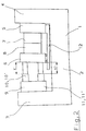
- Fig. 1 the tie bar-less clamping unit can be seen. It consists of a C-frame shaped Power transmission element 1. This consists of a lower connecting part 2, to which two side parts 3 and 4 connect. On one side part 4 there is a first, fixed tool carrier plate 5 arranged. This takes one part 7 of a two-part Injection mold. On the other side part 3 there is an end plate 9 attached.
- the face plate is a separate component, can of course do the same already the side part 3 be so stable that a separate Face plate as such is not required.
- At least two elements act on the end plate 9 to produce it the closing force 10 and 11. They establish the connection to the second, movable tool carrier plate 6, which is also a Tool half 8 carries.
- the leadership of the moving Tool carrier plate 6 relative to the fixed plate 5 is by a Guide element 12 accomplished so that a parallel opening and Closing the tool becomes possible.
- Fig. 2 the clamping unit is shown when it is under load when thus the closing force through the elements 10 (and 10 ') and 11 (and 11') is produced.
- the power transmission element 1 deforms under the Closing force, as shown in Fig. 2 greatly exaggerated.
- the two elements for Generation of the closing force 10 and 11 in relation to the lower one Connecting part 2 of the power transmission element 1 offset in height Position of the tool 7, 8 are arranged. That is, the effective distance of the two elements 10 and 11 of the - largely undeformed - lower connecting part 2 is different, so that due to the Geometry in the event of a bending of the side parts due to the closing force 3 and 4 different amounts, around which the elements 10 or 11 must expand.
- hydraulic piston-cylinder elements are used as elements for generating the closing force. It is provided that both or all four elements 10, 10 ', 11 and 11' are supplied by a common hydraulic oil supply unit. The same hydraulic pressure is applied to all piston-cylinder elements. The result of this is that, with uniform force development, different adjusting movements x 1 or x 2 are carried out automatically in all elements, without special precautions being required for this.
- the hydraulic pressure ratio of the upper (10) to the lower (11) element in one certain relationship to each other is specified. So that can be achieved that a tool with asymmetrically positioned cavities and locally adjusted closing force is duly locked.
Landscapes
- Engineering & Computer Science (AREA)
- Mechanical Engineering (AREA)
- Manufacturing & Machinery (AREA)
- Moulds For Moulding Plastics Or The Like (AREA)
- Injection Moulding Of Plastics Or The Like (AREA)
- Processing And Handling Of Plastics And Other Materials For Molding In General (AREA)
Description
- mindestens ein die Schließkraft übertragendes kraftübertragungselement, das aus einem unteren Verbindungsteil besteht, an dem seitlich je ein Seitenteil angeordnet ist,
- eine erste an einem Seitenteil des Kraftübertragungselements angeordnete Werkzeugträgerplatte,
- eine zweite Werkzeugträgerplatte, die zum Öffnen und Schließen des Werkzeugs in Schließrichtung des Werkzeugs verschiebbar ist,
- eine Stirnplatte, die an einem Seitenteil des Kraftübertragungselements angeordnet ist,
- ein aus mindestens zwei Teilen bestehendes Werkzeug, von dem jeweils eines an der ersten und an der zweiten Werkzeugträgerplatte angeordnet ist, und
- mindestens zwei Elemente zur Erzeugung einer Schließkraft, die zwischen der Stirnplatte und der zweiten Werkzeugträgerplatte angeordnet sind.
- Fig. 1
- zeigt die Seitenansicht der Spritzgießmaschine bzw. deren Schließeinheit, bevor das Werkzeug geschlossen ist,
- Fig. 2
- stellt den Fall dar, daß das Werkzeug mit der Zuhaltekraftbeaufschlagt wird und sich der Maschinenrahmen entsprechend verformt hat.
- 1
- Kraftübertragungselement
- 2
- unteres Verbindungsteil
- 3, 4
- Seitenteile
- 5
- erste (feste) Werkzeugträgerplatte
- 6
- zweite (verschiebbare) Werkzeugträgerplatte
- 7, 8
- Werkzeug
- 9
- Stirnplatte
- 10, 10' 11, 11'
- Elemente zur Erzeugung der Schließkraft
- 12
- Führungselement
- x1
- Stellbewegung der Schließkraft-Elemente 10, 10'
- x2
- Stellbewegung der Schließkraft-Elemente 11, 11'
Claims (6)
- Holmlose Schließeinheit für eine Maschine für die Verarbeitung von spritzgießfähigem Material, insbesondere für eine Kunststoff-Spritzgießmaschine, die aufweist:dadurch gekennzeichnet,mindestens ein die Schließkraft übertragendes Kraftübertragungselement (1), das aus einem unteren Verbindungsteil (2) besteht, an dem seitlich je ein Seitenteil (3, 4) angeordnet ist,eine erste an einem Seitenteil (4) des Kraftübertragungselements (1) angeordnete Werkzeugträgerplatte (5),eine zweite Werkzeugträgerplatte (6), die zum Öffnen und Schließen des Werkzeugs (7, 8) in Schließrichtung des Werkzeugs verschiebbar ist,eine Stirnplatte (9), die an einem Seitenteil (3) des Kraftübertragungselements (1) angeordnet ist,ein aus mindestens zwei Teilen bestehendes Werkzeug (7, 8), von dem jeweils eines an der ersten und an der zweiten Werkzeugträgerplatte (5, 6) angeordnet ist, undmindestens zwei Elemente zur Erzeugung einer Schließkraft (10, 11), die zwischen der Stirnplatte (9) und der zweiten Werkzeugträgerplatte (6) angeordnet sind,
daß die mindestens zwei Elemente zur Erzeugung der Schließkraft (10, 11) in einer in bezug auf den unteren Verbindungsteil (2) des Kraftübertragungselements (1) höhenversetzten Lage des Werkzeugs (7, 8) angeordnet sind, so daß geringfügige Verformungen des Kraftübertragungselements (1) durch unterschiedliche Stellbewegungen (x1, x2) der Elemente (10, 11) ausgeglichen werden, um eine konstante Schließkraftverteilung über die Trennebene der beiden Werkzeughälften (7, 8) zu gewährleisten. - Holmlose Schließeinheit nach Anspruch 1, dadurch gekennzeichnet, daß vier Elemente zur Erzeugung der Schließkraft (10, 10', 11, 11') vorgesehen sind, die in den vier Eckbereichen der rechteckigen Werkzeugaufspannplatte (6) angeordnet sind.
- Holmlose Schließeinheit nach Anspruch 1 oder 2, dadurch gekennzeichnet, daß die mindestens zwei Elemente zur Erzeugung der Schließkraft (10, 11) hydraulisch betätigte Kolben-Zylinder-Elemente sind.
- Holmlose Schließeinheit nach Anspruch 3, dadurch gekennzeichnet, daß beide Elemente zur Erzeugung der Schließkraft (10, 11) von einer gemeinsamen Hydraulikölversorgungseinheit versorgt werden, wobei beide Elemente (10, 11) mit dem gleichen Hydraulikdruck beaufschlagt werden.
- Holmlose Schließeinheit nach Anspruch 3, dadurch gekennzeichnet, daß beide Elemente zur Erzeugung der Schließkraft (10, 11) von einer gemeinsamen Hydraulikölversorgungseinheit versorgt werden, wobei beide Elemente (10, 11) mit einem in einem bestimmten Verhältnis zueinander stehenden unterschiedlichen Hydraulikdruck beaufschlagt werden.
- Holmlose Schließeinheit nach mindestens einem der Ansprüche 1 bis 5, dadurch gekennzeichnet, daß die Führung der beiden Werkzeugträgerplatten (5, 6) zueinander durch mindestens ein Führungselement (12) erfolgt, wobei sich mindestens eine Werkzeugträgerplatte (6) in Schließrichtung auf dem Führungselement (12) bewegen kann und wobei das Führungselement (12) mit einer Werkzeugträgerplatte (5) starr verbunden ist, so daß das Führungselement (12) relativ zum Kraftübertragungselement (1) derart gelagert ist, daß es sich durch die Schließkraft nicht mit verformt.
Applications Claiming Priority (3)
| Application Number | Priority Date | Filing Date | Title |
|---|---|---|---|
| AT1632/95 | 1995-10-03 | ||
| AT163295 | 1995-10-03 | ||
| AT0163295A AT408531B (de) | 1995-10-03 | 1995-10-03 | Schliesseinheit für eine holmlose spritzgiessmaschine |
Publications (2)
| Publication Number | Publication Date |
|---|---|
| EP0767043A1 EP0767043A1 (de) | 1997-04-09 |
| EP0767043B1 true EP0767043B1 (de) | 2000-01-26 |
Family
ID=3517621
Family Applications (1)
| Application Number | Title | Priority Date | Filing Date |
|---|---|---|---|
| EP96113223A Expired - Lifetime EP0767043B1 (de) | 1995-10-03 | 1996-08-17 | Holmlose Schliesseinheit für eine Maschine für die Verarbeitung von spritzgiessfähigem Material |
Country Status (3)
| Country | Link |
|---|---|
| EP (1) | EP0767043B1 (de) |
| AT (2) | AT408531B (de) |
| DE (1) | DE59604279D1 (de) |
Family Cites Families (5)
| Publication number | Priority date | Publication date | Assignee | Title |
|---|---|---|---|---|
| JP2631517B2 (ja) * | 1988-07-08 | 1997-07-16 | ファナック株式会社 | 型締装置 |
| DE4302639C2 (de) * | 1992-01-31 | 1998-02-05 | Nissei Plastics Ind Co | C-förmiges Gestell für die Formschließeinheit einer Spritzgießmaschine |
| DE4209392C2 (de) * | 1992-03-23 | 1995-10-12 | Krauss Maffei Ag | Formschließvorrichtung für eine Spritzgießmaschine |
| EP0717674B1 (de) * | 1993-09-10 | 1997-07-16 | Battenfeld Kunststoffmaschinen Ges.m.b.H. | Holmlose kunststoff-spritzgiessmaschine |
| AT402276B (de) * | 1994-08-31 | 1997-03-25 | Engel Gmbh Maschbau | Schliesseinheit einer spritzgiessmaschine |
-
1995
- 1995-10-03 AT AT0163295A patent/AT408531B/de not_active IP Right Cessation
-
1996
- 1996-08-17 EP EP96113223A patent/EP0767043B1/de not_active Expired - Lifetime
- 1996-08-17 DE DE59604279T patent/DE59604279D1/de not_active Expired - Lifetime
- 1996-08-17 AT AT96113223T patent/ATE189156T1/de not_active IP Right Cessation
Also Published As
| Publication number | Publication date |
|---|---|
| AT408531B (de) | 2001-12-27 |
| ATE189156T1 (de) | 2000-02-15 |
| EP0767043A1 (de) | 1997-04-09 |
| DE59604279D1 (de) | 2000-03-02 |
| ATA163295A (de) | 2001-05-15 |
Similar Documents
| Publication | Publication Date | Title |
|---|---|---|
| DE69003281T2 (de) | Vorrichtung zum Stanzen oder Formen mit Kniehebeln für die hin- und hergehende Bewegung der Werkzeuge. | |
| DE69517467T2 (de) | Kombinierte Formträger und Gestängevorrichtung | |
| DE2921029A1 (de) | Pressen- und formhalteeinrichtung zum verdichten auf dem gebiet der pulvermetallurgie | |
| DE102018221309B4 (de) | Formtransportführungsvorrichtung in einer Spritzgießmaschine | |
| DE102010037534A1 (de) | Vorrichtung und Verfahren zur Herstellung von zumindest teilweise geschlossenen Hohlprofilen mit drehbaren Gesenkhälften und geringer Taktzeit | |
| AT526055B1 (de) | Anordnung mit einer ersten Schließeinheit für eine Formgebungsmaschine | |
| EP3160726B1 (de) | Verbesserte c-gestell-presse | |
| EP0294765B1 (de) | Präzisionsstanzautomat und zugehöriges Verfahren zum Werkzeugwechsel | |
| DE4444941C2 (de) | Stranggießkokille | |
| EP0999926B1 (de) | Holmlose spritzgiessmaschine | |
| DE4426521C1 (de) | Vorrichtung zum Schließen von Formen für die Herstellung von Gegenständen aus Kunststoff | |
| EP0933181A2 (de) | Schliessvorrichtung für Formen zum Herstellen von Gegenständen aus thermoplastischem Kunststoff | |
| DE19643366C2 (de) | Spritzgießmaschine mit einer Werkzeugschließeinrichtung | |
| DE102007058634B4 (de) | Verfahren und Vorrichtung zur Herstellung von flächigen Kunststoff-Formteilen | |
| DE19902998A1 (de) | Transferzuführer und Verfahren seiner Operation | |
| DE19510488C1 (de) | Vorrichtung zum Schließen von Formen für die Herstellung von Gegenständen aus Kunststoff | |
| EP0767043A1 (de) | Holmlose Schliesseinheit für eine Maschine für die Verarbeitung von spritzgiessfähigem Material | |
| DE102007058635B4 (de) | Vorrichtung und Verfahren zur Herstellung von flächigen Kunststoff-Formteilen | |
| DE4104288C2 (de) | Vorrichtung zur Biegekompensation an Formwerkzeugen | |
| EP3024646B1 (de) | Kraftmodul und modulares pressensystem | |
| AT400416B (de) | Stranggiess-plattenkokille | |
| DE3875243T2 (de) | Matrizenaustausch bei pressen. | |
| DE19506077A1 (de) | Vorrichtung zum Transfer von Werkstücken durch eine Folge von Bearbeitungsstationen | |
| EP0689924B1 (de) | Holmlose Schliesseinheit für eine Machine für die Verarbeitung von spritzgiessfähigem Material | |
| EP1849591B1 (de) | Presse |
Legal Events
| Date | Code | Title | Description |
|---|---|---|---|
| PUAI | Public reference made under article 153(3) epc to a published international application that has entered the european phase |
Free format text: ORIGINAL CODE: 0009012 |
|
| AK | Designated contracting states |
Kind code of ref document: A1 Designated state(s): AT DE FR GB IT |
|
| 17P | Request for examination filed |
Effective date: 19970317 |
|
| 17Q | First examination report despatched |
Effective date: 19981209 |
|
| GRAG | Despatch of communication of intention to grant |
Free format text: ORIGINAL CODE: EPIDOS AGRA |
|
| GRAG | Despatch of communication of intention to grant |
Free format text: ORIGINAL CODE: EPIDOS AGRA |
|
| GRAH | Despatch of communication of intention to grant a patent |
Free format text: ORIGINAL CODE: EPIDOS IGRA |
|
| GRAH | Despatch of communication of intention to grant a patent |
Free format text: ORIGINAL CODE: EPIDOS IGRA |
|
| GRAA | (expected) grant |
Free format text: ORIGINAL CODE: 0009210 |
|
| AK | Designated contracting states |
Kind code of ref document: B1 Designated state(s): AT DE FR GB IT |
|
| REF | Corresponds to: |
Ref document number: 189156 Country of ref document: AT Date of ref document: 20000215 Kind code of ref document: T |
|
| REF | Corresponds to: |
Ref document number: 59604279 Country of ref document: DE Date of ref document: 20000302 |
|
| ITF | It: translation for a ep patent filed | ||
| GBT | Gb: translation of ep patent filed (gb section 77(6)(a)/1977) |
Effective date: 20000327 |
|
| ET | Fr: translation filed | ||
| PLBE | No opposition filed within time limit |
Free format text: ORIGINAL CODE: 0009261 |
|
| STAA | Information on the status of an ep patent application or granted ep patent |
Free format text: STATUS: NO OPPOSITION FILED WITHIN TIME LIMIT |
|
| 26N | No opposition filed | ||
| PGFP | Annual fee paid to national office [announced via postgrant information from national office to epo] |
Ref country code: FR Payment date: 20010629 Year of fee payment: 6 |
|
| PGFP | Annual fee paid to national office [announced via postgrant information from national office to epo] |
Ref country code: GB Payment date: 20010803 Year of fee payment: 6 |
|
| REG | Reference to a national code |
Ref country code: GB Ref legal event code: IF02 |
|
| PG25 | Lapsed in a contracting state [announced via postgrant information from national office to epo] |
Ref country code: GB Free format text: LAPSE BECAUSE OF NON-PAYMENT OF DUE FEES Effective date: 20020817 |
|
| GBPC | Gb: european patent ceased through non-payment of renewal fee |
Effective date: 20020817 |
|
| PG25 | Lapsed in a contracting state [announced via postgrant information from national office to epo] |
Ref country code: FR Free format text: LAPSE BECAUSE OF NON-PAYMENT OF DUE FEES Effective date: 20030430 |
|
| REG | Reference to a national code |
Ref country code: FR Ref legal event code: ST |
|
| PGFP | Annual fee paid to national office [announced via postgrant information from national office to epo] |
Ref country code: AT Payment date: 20030825 Year of fee payment: 8 |
|
| PG25 | Lapsed in a contracting state [announced via postgrant information from national office to epo] |
Ref country code: AT Free format text: LAPSE BECAUSE OF NON-PAYMENT OF DUE FEES Effective date: 20040817 |
|
| PG25 | Lapsed in a contracting state [announced via postgrant information from national office to epo] |
Ref country code: IT Free format text: LAPSE BECAUSE OF NON-PAYMENT OF DUE FEES Effective date: 20050817 |
|
| PGFP | Annual fee paid to national office [announced via postgrant information from national office to epo] |
Ref country code: DE Payment date: 20140831 Year of fee payment: 19 |
|
| REG | Reference to a national code |
Ref country code: DE Ref legal event code: R119 Ref document number: 59604279 Country of ref document: DE |
|
| PG25 | Lapsed in a contracting state [announced via postgrant information from national office to epo] |
Ref country code: DE Free format text: LAPSE BECAUSE OF NON-PAYMENT OF DUE FEES Effective date: 20160301 |