EP0764827A2 - Tête de mesure à contact - Google Patents
Tête de mesure à contact Download PDFInfo
- Publication number
- EP0764827A2 EP0764827A2 EP96306799A EP96306799A EP0764827A2 EP 0764827 A2 EP0764827 A2 EP 0764827A2 EP 96306799 A EP96306799 A EP 96306799A EP 96306799 A EP96306799 A EP 96306799A EP 0764827 A2 EP0764827 A2 EP 0764827A2
- Authority
- EP
- European Patent Office
- Prior art keywords
- movable member
- contact
- fixed member
- stylus
- fixed
- Prior art date
- Legal status (The legal status is an assumption and is not a legal conclusion. Google has not performed a legal analysis and makes no representation as to the accuracy of the status listed.)
- Granted
Links
Images


Classifications
-
- G—PHYSICS
- G01—MEASURING; TESTING
- G01B—MEASURING LENGTH, THICKNESS OR SIMILAR LINEAR DIMENSIONS; MEASURING ANGLES; MEASURING AREAS; MEASURING IRREGULARITIES OF SURFACES OR CONTOURS
- G01B7/00—Measuring arrangements characterised by the use of electric or magnetic techniques
- G01B7/004—Measuring arrangements characterised by the use of electric or magnetic techniques for measuring coordinates of points
- G01B7/008—Measuring arrangements characterised by the use of electric or magnetic techniques for measuring coordinates of points using coordinate measuring machines
- G01B7/012—Contact-making feeler heads therefor
- G01B7/016—Constructional details of contacts
-
- G—PHYSICS
- G01—MEASURING; TESTING
- G01B—MEASURING LENGTH, THICKNESS OR SIMILAR LINEAR DIMENSIONS; MEASURING ANGLES; MEASURING AREAS; MEASURING IRREGULARITIES OF SURFACES OR CONTOURS
- G01B5/00—Measuring arrangements characterised by the use of mechanical techniques
- G01B5/004—Measuring arrangements characterised by the use of mechanical techniques for measuring coordinates of points
- G01B5/008—Measuring arrangements characterised by the use of mechanical techniques for measuring coordinates of points using coordinate measuring machines
- G01B5/012—Contact-making feeler heads therefor
- G01B5/016—Constructional details of contacts
Definitions
- the present invention relates to improvements in a touch probe including a fixed member, a movable member, and a reseat position system for allowing the movable member to be displaced relative to the fixed member when a force is externally applied to the movable member and for returning the movable member from which the force is eliminated to a rest position.
- This type of probe is used in a three dimensional coordinate measuring machine or the like.
- a contact element of a three dimensionally movable probe is brought into contact with a workpiece placed on a fixed (granite) table, the instant of contact of the contact element with the workpiece is used as an electrical trigger to read amounts of three dimensional feed in terms of coordinate values along the three axis, and the size and shape of the workpiece are measured on the basis of these coordinate values. Since the probe for use in measurement outputs a contact state with the workpiece as an electrical touch signal, it is called a touch probe and is widely used.
- the touch probe includes a detection system for detecting a slight movement of a stylus having a contact element when it contacts a workpiece, and a safety system for preventing damage to the probe from a substantial movement of the stylus.
- a relief function for substantially moving the stylus relative to the housing of the probe, and a reseat (recovering) function for returning the stylus to the original position after its relief action are required.
- a system having these two functions is called a reseat position system.
- the latter reseat function is a function for locating the stylus at a fixed position, and directly affects measurement repeatability.
- a six-point contact reseat position system has been known as a reseat position system satisfying these two functions.
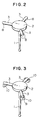
- Fig. 1 illustrates an overall construction of a touch trigger probe having the six-point contact reseat position system.
- a stylus 1 is fixed to a movable member 2.
- Three columns are radially projected from the movable member 2 at 120° spacing about the axial line of the stylus 1 and within a plane perpendicular to the axial line of the stylus 1.
- Three sets of V-shaped locking portions 6 formed by combining two columns are fixed to a fixed member mounted to a probe housing 4 (a bottom wall of the probe housing 3) at positions corresponding to the columns 3 of the movable member 2.
- the combination of the columns, the combination of the column with the hard ball, and the combination of the hard ball with the V-shaped groove form a pair of contact points, and a displacement allowable direction in which the fixed member and the movable member can be relatively displaced while maintaining the contact at these contact points is restricted.
- the displacement allowable direction is, for example, the direction of the V-shaped groove in the case of the combination of the hard ball and the V-shaped groove, and the axial direction of the column in the case of the combination of the column and the hard balls.
- Fig. 4 is a partially enlarged view of the reseat position system shown in Fig. 3. Referring to Fig. 4, a movement of the hard ball 9 along the first direction is prevented, and the movement of the hard ball 9 along the second direction is prevented by a pressing force applied on the hard ball 9. Therefore, the hard ball 9 is allowed to move only along the third direction.
- the first, second and third directions are perpendicular to one another.
- the contact surfaces at the contact points of two components include the displacement allowable direction or displacement allowable surface.
- Some techniques are used so as not to generate plastic deformation or wear when the columns 3 and the hard balls 8, 9 repeatedly come into contact with each other. Such techniques include the use of cemented carbide, etc. to make the columns 3 and the hard balls 8 and 9.
- the reseat position system as described above offers ideal position reproducibility because a stable position of the movable member is directly and exclusively determined.
- the ideal position reproducibility can be offered only when frictional force acting on the contact points is zero.
- the position reproducibility deteriorates due to the frictional force.
- the frictional forces act in various directions, and hence the magnitude of the forces acting between the hard ball and the wall surfaces of the V-shaped groove differs variously, so that the position reproducibility is deteriorated.
- the direction of the frictional forces is determined by a direction of relative slide between the hard ball and the V-shaped groove.
- the fixed member and the movable member are devised to vibrate relatively so as to increase the position reproducibility (Dither Effect).
- to vibrate means "to move repeatedly", a certain period of time is required and there causes wear and deterioration of the contact portions.
- coarseness of the contact portions seriously affects on the position reproducibility.
- Dither Effect it is necessary to select frequencies and amplitudes. Proper selection of the frequencies and amplitudes exhibits the effect.
- an environmental condition such as a change of a coefficient of friction is changed, it is necessary to re-adjust the frequencies and amplitudes. Therefore, a high position reproducibility for a long period of time cannot be secured.
- the present invention is intended to increase reproducibility of a return position not by reducing the magnitude of a frictional force acting on each contact point, but by aligning the direction of the frictional force to one direction.
- a touch probe which comprises: a fixed member mounted to a housing; a movable member; a reseat position system which permits the fixed member and the movable member to make contact with each other at a pair of contact points at each of three positions which are spaced from one another so as to determine directly and exclusively the relative position between the fixed member and the movable member; a stylus mounted to the movable member and having a contact element at the distal end thereof which comes into contact with a workpiece; a bias means for allowing the movable member to be displaced relative to the fixed member when a force is externally applied to the contact element and for returning the movable member to a rest position when the force applied to the contact element is eliminated; and a displacement system which, when operating, causes a relative displacement between the fixed member and the movable member at each of contact points always in a fixed direction following specified procedures while maintaining a contacting state of the fixed member and the movable member in the res
- the displacement system according to the present invention may employ a plurality of piezoelectric element so as to make the direction of relative displacement between the fixed member and the movable member at each contact point into a plurality of different directions, and further, to make these directions into radial directions about the axis of the stylus.
- Fig. 5 is an exploded perspective view of a touch probe which has a reseat position system using piezoelectric elements according to an embodiment of the present invention.
- the reseat position system includes a fixed member 11, a movable member 21, and a bias means (this is not shown but is the same as the biasing spring 7 shown in Fig. 1) for allowing the movable member 21 to be displaced relative to the fixed member when a force is externally applied to the movable member 21 and for returning the movable member 21 from which the force is eliminated to a rest position.
- the fixed member 11 is fixed at its center portion to a housing of the probe, and has three arms 121 to 123 radially extending at 120° spacing about an axis of a stylus 22.
- Hard balls 131 to 133 are disposed on the upper surfaces of the tip ends of the arms 121 to 123, respectively.
- the center positions of the hard balls are at equal distances from the axis of the stylus 22 and spaced at 120°.
- receptacle through holes 141 to 143 are formed inside of the hard balls 131 to 133 so as to open both in the upper and lower surfaces of the arms, and piezoelectric elements 151 to 153, which are actuating elements for a displacement system, are embedded in the storage slots, respectively, in a preloaded condition.
- the piezoelectric elements 151 to 153 are so disposed as to expand and contract along the radial direction. Therefore, when a voltage is applied to the piezoelectric elements 151 to 153, the hard balls 131 to 133 are substantially radially displaced about the axis of the stylus 22.
- An aperture 16 is punched in the center of the fixed member 11, and the stylus 22 of the movable member 21 is inserted therethrough.
- the stylus 22 is projected squarely and downwardly from the center of the movable member 21.
- a spherical contact element 23, which contacts a workpiece, is provided at the lower end portion of the stylus 22.
- V-shaped grooves 241 to 243 are provided in the movable member 21 at three points which are each located 120° apart from one another. The V-shaped grooves 241 to 243 are disposed so that the directions thereof substantially coincide with the radial direction.
- the movable member 21 is seated on the fixed member 11.
- the hard balls 131 to 133 are received in the corresponding V-shaped grooves 241 to 243 and each hard ball comes into contact with the corresponding V-shaped groove at two points, i.e., at six points in total, so that the movable member 21 rests on the fixed member 11.
- Fig. 6 is a block diagram showing a circuit system of this embodiment.
- the circuit in this embodiment consists of a contact detecting circuit 31 for detecting displacement of the movable member 21 caused by the contact of the contact element 23 with the workpiece and for outputting a touch signal, and a displacement control circuit 32 for applying a specified voltage to the piezoelectric elements 151 to 153 with a time reference of the touch signal input. Therefore, when the displacement of the movable member 21 is detected by the contact detecting circuit 31, the touch signal is outputted, and the displacement control circuit 32 receives the signal and applies the specified voltage to the piezoelectric elements 151 to 153 at a proper timing.
- Fig. 7(a) is a diagram showing a waveform of the voltage applied to the piezoelectric elements 151 to 153 and illustrates when the piezoelectric elements 151 to 153 are driven during a probing operation.
- one cycle of the probing operation generally consists of the following periods or states: a "contact" state A in which the contact element is in contact with the workpiece; and a "seated” state B between the instance when the contact element is retracted from the workpiece and the instant when the contact element is prepared to contact with the workpiece again, i.e., a "stable" stae E.
- a period for greatly displacing the stylus to recover the seated condition i.e., a "moving" period C
- the displacement control circuit 32 activates the piezoelectric elements for a fixed period of time D after the period C has elapsed since a detecting signal output from the contact detecting circuit 32 disappeared.
- the voltage to be applied to the piezoelectric elements 151 to 153 is, for example, shown by VE1 in Fig.
- the square-shaped voltage VE2 shown in Fig.(b) and tge triangle-shaped voltage VE3 shown in Fig.7(c are able to be used in the first and the following other embodiments.
- the piezoelectric elements 151 to 153 impart expand-contract displacement to the arms 121 to 123 such that the hard balls 131 to 133 come closer to and then go away from the aperture 16 (or vise versa).
- the hard balls 131 to 133 are displaced in the above-described displacement allowable direction to align the direction of frictional force at each point of contact in one direction, resulting in obtaining a high return accuracy for the movable member 21 to the specified position.
- the frictional force and a force applied on the V-shaped grooves can be always kept constant, thereby eliminating variations in the seated position of the movable member 21.
- the displacement is micro-fine, a relative movement between the hard balls and V-shaped grooves can be produced. Therefore, it is not necessary that the fixed direction to be displaced by the piezoelectric elements strictly coincides with the direction of the V-shaped grooves. Even if there is a notable deviation between these direction, it is possible to align the direction of frictional forces in one direction provided that such deviation is small enough to allow the relative movement between the hard balls and the V-shaped grooves to be produced.
- the hard balls 131 to 133 are displaced relative to the three V-shaped grooves. In the present invention, however, it is essential to produce a relative displacement between the hard balls 131 to 133 and the V-shaped grooves 241 to 243 in a specified direction. Therefore, the V-shaped grooves 241 to 243 may be quite safely displaced relative to the three hard balls 131 to 133.
- Fig. 8 illustrates a second embodiment according to the present invention.
- receptacle through holes 411 to 413 are formed on straight lines connecting the centers of adjacent hard balls 131 to 133, and the piezoelectric elements 151 to 153 are disposed in each of the receptacle holes 411 to 413 in a preloaded condition.
- the direction of expansion and contraction of the piezoelectric elements 151 to 153 is different from the radial direction about the axis of the stylus 22, the hard balls 131 to 133 are substantially radially displaced by a resultant of forces applied thereto.
- the overall diameter of the probe apparatus can be made small.
- Fig. 9 illustrates a third embodiment according to the present invention.
- a large hexagonal through hole 42 is formed in the center of the fixed member 11, and one hollow ring-shaped piezoelectric element 154 is disposed within the through hole 42 through three pressing elements 431 to 433.
- the stylus 22 passes through a center hollow portion of the piezoelectric element 154.
- the probe apparatus is realized by one piezoelectric element 154, the numbers of parts or components and the number of assembly steps can be reduced.
- Figs. 10 and 11 illustrate a fourth embodiment according to the present invention.
- the hard balls 131 to 133 are displaced by bending the fixed member 11.
- a through hole 44 having three contact peripheral surfaces is formed in the center of the fixed member 11
- relief grooves 4613, 4612, 4623 each having thin-wall portions 451A and 453B, 451B and 452A, 452B and 453A are formed at both sides of each of the contact peripheral surfaces 441 to 443
- the hollow ring-shaped piezoelectric element 154 is disposed to be brought into contact with the inner peripheral surfaces of the contacting peripheral surfaces 441 to 443.
- the contact peripheral surfaces 441 to 443 are formed among the hard balls 131 to 133.
- the piezoelectric element 154 expands and contracts, the forces shown by arrows A in Fig. 11 act on the fixed member 11. Therefore, the hard balls 131 to 133 can be substantially radially displaced relative to the axis of the stylus 22 by actions of the thin-wall portions 451A and 453B, 451B and 452A, 452B and 453A, respectively. According to this embodiment, the same effect as the third embodiment shown in Fig. 9 can be expected.
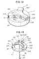
- Fig. 12 illustrates a fifth embodiment according to the present invention.
- an exciting coil is employed as an actuation means, i.e., an exciting coil 47 is contained in the fixed member 11 so as to compress the center portion of the movable member 21, which is composed of a magnetic substance, with an ambient force.
- the V-shaped grooves 241 to 243 are formed in three portions of the movable member 21, and hinges 481 to 483 are provided inside thereof, respectively.
- the center portion of the movable member 21 is compressed by the exciting coil 47, the center portion is vertically displaced. Therefore, the V-shaped grooves 241 to 243 can be substantially radially displaced relative to corresponding hard balls 131 to 133. According to this embodiment, the same effect as the third embodiment shown in Fig. 9 can also be expected.
- FIG. 13 which illustrates the entire construction of this embodiment, the fixed member 61 consists of a ring-shaped member which is fixed to an opening end portion of a probe housing having a cylindrical shape with a bottom (not shown, and hereinafter, referred to as a bottomed cylindrical probe housing), and three blocks 24 are spaced at 120° apart on the upper surface of the ring-shaped member.
- the V-shaped grooves 241 to 243 are formed in the upper portions of the blocks 24.
- a coil spring 63 is provided as a bias means which is the same as the biasing spring 7.
- a movable member 62 has three arms 621 to 623 radially extending at 120° spacing from the center thereof where the stylus 22 is mounted, and the hard balls 131 to 133 are disposed on the lower surfaces of the distal ends of the respective arms 621 to 623. The hard balls 131 to 133 are received in the corresponding V-shaped grooves 241 to 243, so that the position of the movable member 62 relative to the fixed member 61 is directly and exclusively determined.
- Each of the arms 621 to 623 have receptacle through holes (not shown), and the piezoelectric elements 151 to 153 are embedded therein in a preloaded condition.
- the piezoelectric elements 151 to 153 are so disposed as to expand and contract substantially along the radial direction.
- the axial direction (the direction in which the hard balls 131 to 133 and the V-shaped grooves 241 to 243 are relatively moved) of the V-shaped grooves 241 to 243 is substantially the radial direction about the axis of the stylus 22 in Fig. 13, the direction of the V-shaped grooves 241 to 243 is not limited thereto.
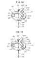
- the V-shaped grooves 241 to 243 may be oriented to a substantially circumferential direction (an angle slightly deviated from the circumferential direction), or the V-shaped grooves 241 to 243 may be oriented at random angles, as shown in Figs. 15 and 16. In Figs. 14 and 15, the piezoelectric elements are omitted.
- a position of an object is directly and exclusively determined by three translation components and three rotational components, and a spatial position of a rigid body is determined by six restrictions. Therefore, according to the sixth embodiment, the action and effect similar to those of the first embodiment can be obtained.
- the V-shaped grooves 241 to 243 may be inclined toward the axis of the stylus 22, and the hard balls 131 to 133 may be mounted to the ends of the arms 621 to 623 of the movable member 62 so that they are brought into contact with the corresponding V-shaped grooves 241 to 243.
- Each of the arms 621 to 623 are provided with piezoelectric elements (not shown).
- a seventh embodiment of the present invention will be described with reference to Figs. 19 and 20.
- the seventh embodiment differs from the sixth embodiment in the construction of convergent surfaces.
- the other constructions are the same as those of the sixth embodiment.
- a fixed member 71 consists of a ring-shaped member which is fixed to an opening end portion of a bottomed cylindrical probe housing (not shown), and the inner peripheral surface of the ring-shaped member is formed into six tapered surfaces 711 to 716, which are portions of side surfaces of an imaginary hexagonal pyramid. It is assumed that the apex of the imaginary hexagonal pyramid is located on the axial line of the stylus 22.
- the movable member 72 has six arms 721 to 726 radially extending at 60° spacing from the center thereof where the stylus 22 is mounted, and hard balls 131 to 136 are disposed on the lower surfaces of the distal ends of the respective arms 721 to 726.
- the hard balls 131 to 136 come into contact with the corresponding tapered surfaces 711 to 716, so that the position of the movable member 72 relative to the fixed member 71 is directly and exclusively determined.
- Each of the arms 721 to 726 have receptacle through holes (not shown), and the piezoelectric elements 151 to 156 are embedded therein in a preloaded condition.
- the piezoelectric elements 151 to 156 are so disposed as to expand and contract substantially along the radial direction. Therefore, according to the seventh embodiment, action and effects similar to those of the sixth embodiment can be obtained.
- the inner peripheral surface of the fixed member 71 may be formed into three tapered surfaces 71A, 71B and 71C which are portions of side surfaces of an imaginary trigonal pyramid.
- two hard balls 131 and 132 come into contact with one tapered surface 71A (71B or 71C).
- FIG. 21 is a perspective view which illustrates a major portion of the eighth embodiment
- Fig. 22 is a sectional view of Fig. 21.
- the fixed member 71 consists of a ring-shaped member which is fixed to an opening end portion of a bottomed cylindrical probe housing (not shown), and the inner peripheral surface of the ring-shaped member is formed into tapered surfaces 71A, 71B, 71C, which are portions of side surfaces of an imaginary trigonal pyramid. It is assumed that the apex of the imaginary trigonal pyramid is located on the axial line of the stylus 22.
- a movable member 82 is formed in the shape of a frustum of a trigonal pyramid having three tapered surfaces 82A, and the stylus 22 is mounted to the center thereof.
- Each of the tapered surfaces 82A have two hard balls 13, i.e., six hard balls in total. Two hard balls 13 come into contact with one tapered surface 71A (71B or 71C).
- Fig. 23A is an enlarged view of the mounting design of the hard ball 13.
- a receptacle through hole 82B is formed in the tapered surface 82A of the movable member 82.
- Two sets of thin plates 83 i.e., four sheets in total, are disposed opposite to each other with predetermined intervals, and a block 84 in which the hard ball 13 is partially embedded is supported and fixed at the ends of the thin plates 83.
- a piezoelectric element 15 is placed in a space formed by the side surface of the block 84, two sheets of the thin plates 83, and the side surface of the receptacle through hole 82B.
- Two piezoelectric elements 15 are disposed on opposite sides of the block 84, and electrically controlled in such a manner that one of them contracts when the other one expands.
- the piezoelectric elements 15 overcome the rigidity of the thin plates 83 to expand and contract, so that the hard ball 13 is displaced through the block 84.
- the V-shaped groove 241 may be displaced by two piezoelectric elements 15 which are disposed in such a manner that they sandwich a member 24 of the V-shaped groove 241. More specifically, as shown in Fig. 23B, a receptacle hole 61B is formed in a fixed member 61B, four sheets of thin plates are disposed on the side surfaces of the receptacle hole 61B, and a block 24 on which the V-shaped groove 241 is formed is supported and fixed at the ends of the thin plates 83. The piezoelectric 15 is placed in a space formed by the side surface of the block 24, two sheets of the thin plates 83, and the side surface of the receptacle hole 61B. Two piezoelectric elements 15 are disposed on opposite sides of the block 24.
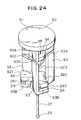
- a fixed member 91 includes a disc-like base 92, a plurality of (three) brackets 93 provided at lower portion of the periphery of the base 92, and blocks 24 provided at lower ends of each of the brackets 93.
- the bracket 93 is a plate member which is disposed so that the direction of the length thereof coincides with the direction of the axial line of the stylus 22, and thin-walled portion 93A serving as a hinge which permits the bracket 93 to move in the direction perpendicular to the axial line of the stylus 22 is formed in part-way of the bracket 93.
- Each of the brackets 93 include first and second side plates 93B and 93C at portions lower than the thin-walled portions 93A.
- Blocks 24 are formed at the distal ends of the first side plates 93B, and V-shaped grooves 241 formed in the blocks 24 support the hard balls provided on arms 621 to 623 of a movable member 62.
- a push plate 94 is supported at the distal ends of the second side plates 93C.
- the push plate 94 and the base 92 support and fix one actuator (displacement means) 95 therebetween.
- the actuator 95 is a piezoelectric element which vertically expands and contracts so as to displace three V-shaped grooves 241 simultaneously.
- Fig. 25 illustrates a state in which a bias means 97 is disposed on the movable member 62.
- the bias means 97 may be a magnetic force generation system which displaces the movable member 62 relative to the fixed member 91 with a magnetic force, or a fluid pressure generation system which displaces the movable member 62 relative to the fixed member 91 with a fluid pressure.
- the fixed member 91 includes the base 92 and a plurality of brackets 93 which are displaceably provided to the base 92 and the V-shaped grooves 241 are formed therein, and the displacement means expands and contracts so as to displace the V-shaped grooves 241 formed between the base 92 and the bracket 93, only one actuator 95 is sufficient to cause relative displacement between the hard balls 13 and the V-shaped grooves 241. Therefore, the structure of the apparatus can be simplified.
- Fig. 26 is a perspective view of a main part of this embodiment which illustrates a state in which a movable member 500 and a fixed member 600 are in contact with each other.
- the movable member 500 consists of a member 501 having a shape of a triangle table, and a member 502 fitted to the leg portion of the member 501.
- a stylus is fitted in a through hole 503 which is formed in the center of the member 502.
- Three columns 504 are embedded in upper portions of each of the side surfaces of the member 501, and the axial directions of these columns 504 form equal azimuth angles one to the other around the axis Z of the stylus.
- the fixed member 600 has three side-plate members 601 formed at the end of the plate-like members thereof, and lower halves of two hard balls 602 are embedded in the upper end surface of each side-plate member 601.
- the center of the fixed member 600 is disposed in the inner space of the movable member 500, and is connected to the movable member 500 by means of a spring (not shown). By a tensile force of the spring, the columns 504 of the movable member 500 come into contact with the hard balls 602 of the movable member at six points.
- Fig. 27 is a view of the fixed member 600 viewed from above which illustrates the contact of two side-plate members 601 with two columns 504, and the cross-section of the lower portion of the rest side-plate member 601.
- Square receptacle through holes 603 are formed, respectively, in the centers of the arms extending in three directions of the fixed member 600 and piezoelectric elements 700 are embedded therein.
- Threaded holes 604 which reach the receptacle through holes 603 are formed in the ends of each of three arms of the fixed member 600.
- Fig. 28 shows the plane of ⁇ 300 nanometers in which a probe contact element provided at the distal end of the probe is perpendicular to the axis of the probe.
- a force was applied to the probe contact element at equal azimuth angle of 10° around the axis of the probe, and the positions of the probe contact element when returned to the rest position were measured by a special device.
- the probe contact element was not displaced in its seated state, the result represented by 36 fine circles concentrated in three portions within a circle P shown by dotted lines was obtained.
- the probe contact element was displaced in its seated position, the result represented by 36 fine circles concentrated within a circle Q shown by dotted lines was obtained.
Applications Claiming Priority (3)
| Application Number | Priority Date | Filing Date | Title |
|---|---|---|---|
| JP246066/95 | 1995-09-25 | ||
| JP24606695 | 1995-09-25 | ||
| JP24606695 | 1995-09-25 |
Publications (4)
| Publication Number | Publication Date |
|---|---|
| EP0764827A2 true EP0764827A2 (fr) | 1997-03-26 |
| EP0764827A3 EP0764827A3 (fr) | 1998-01-07 |
| EP0764827B1 EP0764827B1 (fr) | 2001-11-21 |
| EP0764827B2 EP0764827B2 (fr) | 2005-05-04 |
Family
ID=17142964
Family Applications (1)
| Application Number | Title | Priority Date | Filing Date |
|---|---|---|---|
| EP96306799A Expired - Lifetime EP0764827B2 (fr) | 1995-09-25 | 1996-09-17 | Tête de mesure à contact |
Country Status (3)
| Country | Link |
|---|---|
| US (1) | US5756886A (fr) |
| EP (1) | EP0764827B2 (fr) |
| DE (1) | DE69617148T3 (fr) |
Cited By (9)
| Publication number | Priority date | Publication date | Assignee | Title |
|---|---|---|---|---|
| EP1061326A1 (fr) * | 1999-06-16 | 2000-12-20 | Mitutoyo Corporation | Système pour la reproduction de la mise en place d'une sonde de tâtonnement avec un déplacement double des points de contact |
| EP1061327A2 (fr) * | 1999-06-18 | 2000-12-20 | Mitutoyo Corporation | Système de repositionnement |
| US6198298B1 (en) * | 1997-12-24 | 2001-03-06 | Mitutoyo Corporation | Touch-signal probe |
| EP1262733A2 (fr) * | 2001-05-31 | 2002-12-04 | Mitutoyo Corporation | Palpeur à signal de contact et méthode et appareil pour traiter le signal |
| EP1610087A1 (fr) * | 2004-06-22 | 2005-12-28 | Tesa SA | Palpeur avec déclencheur |
| EP1316778B1 (fr) * | 2001-11-30 | 2007-07-25 | Tesa Sa | Palpeur à déclenchement et procédé d'assemblage d'un palpeur à déclenchement |
| EP2629049A2 (fr) | 2012-02-20 | 2013-08-21 | Tesa Sa | Palpeur |
| US9835433B1 (en) | 2017-05-09 | 2017-12-05 | Tesa Sa | Touch trigger probe |
| US10632624B2 (en) | 2016-07-26 | 2020-04-28 | Illinois Tool Works Inc. | Tool holders for robotic systems having collision detection |
Families Citing this family (16)
| Publication number | Priority date | Publication date | Assignee | Title |
|---|---|---|---|---|
| IT1299955B1 (it) | 1998-04-06 | 2000-04-04 | Marposs Spa | Testa per il controllo di dimensioni lineari di pezzi. |
| GB2336433B (en) * | 1998-04-14 | 2002-02-06 | Mitutoyo Corp | Touch signal probe |
| EP1443300B1 (fr) * | 2003-01-29 | 2010-02-24 | Tesa SA | Palpeur orientable |
| EP1443301B1 (fr) * | 2003-01-29 | 2010-02-10 | Tesa SA | Palpeur orientable |
| US7000451B1 (en) * | 2003-11-17 | 2006-02-21 | Wegand John C | Friction testing device |
| DE102005015890B4 (de) * | 2005-02-24 | 2007-05-03 | Wolfgang Madlener | Tastfühler |
| CN101949696B (zh) * | 2010-08-30 | 2012-07-04 | 西安共达精密机器有限公司 | 一种可更换测针的定位锁紧机构 |
| EP2657642A1 (fr) * | 2012-04-24 | 2013-10-30 | Hexagon Technology Center GmbH | Élément de capteur pour une machine de mesure, en particulier une machine de mesure de coordonnées |
| FR2997180B1 (fr) * | 2012-10-24 | 2015-01-16 | Commissariat Energie Atomique | Etalon metrologique bidimensionnel |
| JP5846462B1 (ja) * | 2014-10-28 | 2016-01-20 | 株式会社東京精密 | 形状測定装置 |
| JP2016161526A (ja) * | 2015-03-05 | 2016-09-05 | 株式会社ミツトヨ | 接触型プローブ |
| US9528824B2 (en) * | 2015-03-31 | 2016-12-27 | Mitutoyo Corporation | Tactile probing system |
| JP6730894B2 (ja) * | 2016-09-20 | 2020-07-29 | Dmg森精機株式会社 | 検出装置 |
| CN107538276A (zh) * | 2017-06-16 | 2018-01-05 | 孟庆周 | 一种测量头定位结构 |
| CN108871170B (zh) * | 2018-06-29 | 2021-03-02 | 深圳清华大学研究院 | 触发式测头预紧力的配置方法及三坐标测量机 |
| CN111352512B (zh) * | 2020-03-04 | 2021-07-06 | 深圳市鸿合创新信息技术有限责任公司 | 被动式电容笔及其笔头结构 |
Citations (4)
| Publication number | Priority date | Publication date | Assignee | Title |
|---|---|---|---|---|
| EP0351713A2 (fr) † | 1988-07-20 | 1990-01-24 | Firma Carl Zeiss | Méthode et arrangement pour l'opération d'un palpeur du type interrupteur |
| EP0501710A1 (fr) * | 1991-02-25 | 1992-09-02 | Renishaw Metrology Limited | Palpeur à contact |
| WO1992021932A1 (fr) * | 1991-05-25 | 1992-12-10 | Renishaw Metrology Limited | Palpeur de mesure |
| DE9320852U1 (de) * | 1993-12-03 | 1995-03-09 | Heidenhain Gmbh Dr Johannes | Mehrkoordinaten-Tastkopf |
Family Cites Families (8)
| Publication number | Priority date | Publication date | Assignee | Title |
|---|---|---|---|---|
| US4153998A (en) * | 1972-09-21 | 1979-05-15 | Rolls-Royce (1971) Limited | Probes |
| DE2712181C3 (de) * | 1977-03-19 | 1981-01-22 | Fa. Carl Zeiss, 7920 Heidenheim | Tastsystem |
| GB8431746D0 (en) * | 1984-12-17 | 1985-01-30 | Renishaw Plc | Contact-sensing probe |
| DE3508396C1 (de) * | 1985-03-08 | 1985-09-12 | Dr. Johannes Heidenhain Gmbh, 8225 Traunreut | Mehrkoordinaten-Tastkopf |
| DE3763885D1 (de) * | 1986-04-17 | 1990-08-30 | Renishaw Plc | Probe fuer kontakt-sensor. |
| DE3728578A1 (de) * | 1987-08-27 | 1989-03-09 | Zeiss Carl Fa | Tastsystem fuer koordinatenmessgeraete |
| SU1647223A1 (ru) * | 1989-04-11 | 1991-05-07 | Вильнюсский Филиал Экспериментального Научно-Исследовательского Института Металлорежущих Станков | Измерительна головка |
| WO1992009862A1 (fr) * | 1990-11-24 | 1992-06-11 | Renishaw Plc | Sonde tactile |
-
1996
- 1996-09-17 EP EP96306799A patent/EP0764827B2/fr not_active Expired - Lifetime
- 1996-09-17 DE DE69617148T patent/DE69617148T3/de not_active Expired - Lifetime
- 1996-09-25 US US08/725,214 patent/US5756886A/en not_active Expired - Lifetime
Patent Citations (5)
| Publication number | Priority date | Publication date | Assignee | Title |
|---|---|---|---|---|
| EP0351713A2 (fr) † | 1988-07-20 | 1990-01-24 | Firma Carl Zeiss | Méthode et arrangement pour l'opération d'un palpeur du type interrupteur |
| US5018280A (en) * | 1988-07-20 | 1991-05-28 | Carl-Zeiss-Stiftung, Heidenheim/Brenz | Method and device for the operation of a workpiece-contacting probe head of the switching type |
| EP0501710A1 (fr) * | 1991-02-25 | 1992-09-02 | Renishaw Metrology Limited | Palpeur à contact |
| WO1992021932A1 (fr) * | 1991-05-25 | 1992-12-10 | Renishaw Metrology Limited | Palpeur de mesure |
| DE9320852U1 (de) * | 1993-12-03 | 1995-03-09 | Heidenhain Gmbh Dr Johannes | Mehrkoordinaten-Tastkopf |
Cited By (21)
| Publication number | Priority date | Publication date | Assignee | Title |
|---|---|---|---|---|
| US6198298B1 (en) * | 1997-12-24 | 2001-03-06 | Mitutoyo Corporation | Touch-signal probe |
| US6678966B1 (en) | 1999-06-16 | 2004-01-20 | Mitutoyo Corporation | Reseat system of touch signal probe |
| EP1061326A1 (fr) * | 1999-06-16 | 2000-12-20 | Mitutoyo Corporation | Système pour la reproduction de la mise en place d'une sonde de tâtonnement avec un déplacement double des points de contact |
| EP1061327A2 (fr) * | 1999-06-18 | 2000-12-20 | Mitutoyo Corporation | Système de repositionnement |
| EP1061327A3 (fr) * | 1999-06-18 | 2001-09-12 | Mitutoyo Corporation | Système de repositionnement |
| US6523273B1 (en) | 1999-06-18 | 2003-02-25 | Mitutoyo Corporation | Reseat system for touch probe in coordinates measuring machine |
| EP1262733A2 (fr) * | 2001-05-31 | 2002-12-04 | Mitutoyo Corporation | Palpeur à signal de contact et méthode et appareil pour traiter le signal |
| EP1262733A3 (fr) * | 2001-05-31 | 2006-05-31 | Mitutoyo Corporation | Palpeur à signal de contact et méthode et appareil pour traiter le signal |
| EP1316778B1 (fr) * | 2001-11-30 | 2007-07-25 | Tesa Sa | Palpeur à déclenchement et procédé d'assemblage d'un palpeur à déclenchement |
| CN100371674C (zh) * | 2004-06-22 | 2008-02-27 | 特莎有限公司 | 触摸探针 |
| EP1610087A1 (fr) * | 2004-06-22 | 2005-12-28 | Tesa SA | Palpeur avec déclencheur |
| US7347000B2 (en) | 2004-06-22 | 2008-03-25 | Tesa Sa | Touch probe |
| EP2629049A2 (fr) | 2012-02-20 | 2013-08-21 | Tesa Sa | Palpeur |
| EP2629048A2 (fr) | 2012-02-20 | 2013-08-21 | Tesa Sa | Palpeur |
| US9057598B2 (en) | 2012-02-20 | 2015-06-16 | Tesa Sa | Touch probe |
| US9057599B2 (en) | 2012-02-20 | 2015-06-16 | Tesa Sa | Touch probe |
| US10632624B2 (en) | 2016-07-26 | 2020-04-28 | Illinois Tool Works Inc. | Tool holders for robotic systems having collision detection |
| US11772277B2 (en) | 2016-07-26 | 2023-10-03 | Illinois Tool Works Inc. | Tool holders for robotic systems having collision detection |
| US9835433B1 (en) | 2017-05-09 | 2017-12-05 | Tesa Sa | Touch trigger probe |
| EP3401635A1 (fr) | 2017-05-09 | 2018-11-14 | Tesa Sa | Sonde de déclenchement par contact |
| US10228229B2 (en) | 2017-05-09 | 2019-03-12 | Tesa Sa | Touch trigger probe |
Also Published As
| Publication number | Publication date |
|---|---|
| EP0764827B1 (fr) | 2001-11-21 |
| DE69617148T2 (de) | 2002-05-02 |
| DE69617148D1 (de) | 2002-01-03 |
| DE69617148T3 (de) | 2005-11-10 |
| EP0764827B2 (fr) | 2005-05-04 |
| US5756886A (en) | 1998-05-26 |
| EP0764827A3 (fr) | 1998-01-07 |
Similar Documents
| Publication | Publication Date | Title |
|---|---|---|
| EP0764827B1 (fr) | Tête de mesure à contact | |
| US8063383B2 (en) | Inertial positioner and an optical instrument for precise positioning | |
| RU2293945C2 (ru) | Чувствительное к смещению устройство | |
| US7398603B2 (en) | Distance measuring probe with air discharge system | |
| US5979070A (en) | Method and apparatus for selectively locking a movement direction of a coordinate measurement probe | |
| JPS62501234A (ja) | 接触−感知プロ−ブ | |
| US10239213B1 (en) | Flexure assembly for force/torque sensing | |
| JPH07119814B2 (ja) | 微小運動用調節装置 | |
| EP1857771B1 (fr) | Palpeur et instrument de mesure du contour | |
| JP3323081B2 (ja) | タッチ信号プローブ | |
| GB2049198A (en) | Probe for use in measuring apparatus | |
| US4040685A (en) | Measuring apparatus | |
| JP2020056700A (ja) | 硬さ試験機 | |
| US6059250A (en) | Tilting device | |
| JP3352055B2 (ja) | タッチ信号プローブの着座機構 | |
| US20200240576A1 (en) | Orthogonal two axis kinematic translation stage | |
| EP1061327B1 (fr) | Système de repositionnement | |
| JP7228689B2 (ja) | リニアドライブ | |
| JPS59170704A (ja) | 測定探子 | |
| JPH1026519A (ja) | プローブの着座機構 | |
| WO2004036727A2 (fr) | Appareil de commande | |
| WO2023036887A1 (fr) | Sonde de balayage | |
| JP3618031B2 (ja) | 着座機構 | |
| JP3810651B2 (ja) | タッチ信号プローブの着座機構 | |
| JP3581433B2 (ja) | 角度変位機構 |
Legal Events
| Date | Code | Title | Description |
|---|---|---|---|
| PUAI | Public reference made under article 153(3) epc to a published international application that has entered the european phase |
Free format text: ORIGINAL CODE: 0009012 |
|
| AK | Designated contracting states |
Kind code of ref document: A2 Designated state(s): CH DE GB LI NL |
|
| PUAL | Search report despatched |
Free format text: ORIGINAL CODE: 0009013 |
|
| AK | Designated contracting states |
Kind code of ref document: A3 Designated state(s): CH DE GB LI NL |
|
| 17P | Request for examination filed |
Effective date: 19980619 |
|
| GRAG | Despatch of communication of intention to grant |
Free format text: ORIGINAL CODE: EPIDOS AGRA |
|
| 17Q | First examination report despatched |
Effective date: 20010105 |
|
| GRAG | Despatch of communication of intention to grant |
Free format text: ORIGINAL CODE: EPIDOS AGRA |
|
| GRAH | Despatch of communication of intention to grant a patent |
Free format text: ORIGINAL CODE: EPIDOS IGRA |
|
| GRAH | Despatch of communication of intention to grant a patent |
Free format text: ORIGINAL CODE: EPIDOS IGRA |
|
| GRAA | (expected) grant |
Free format text: ORIGINAL CODE: 0009210 |
|
| AK | Designated contracting states |
Kind code of ref document: B1 Designated state(s): CH DE GB LI NL |
|
| REG | Reference to a national code |
Ref country code: CH Ref legal event code: EP |
|
| REG | Reference to a national code |
Ref country code: CH Ref legal event code: NV Representative=s name: ISLER & PEDRAZZINI AG |
|
| REG | Reference to a national code |
Ref country code: GB Ref legal event code: IF02 |
|
| REF | Corresponds to: |
Ref document number: 69617148 Country of ref document: DE Date of ref document: 20020103 |
|
| PLBI | Opposition filed |
Free format text: ORIGINAL CODE: 0009260 |
|
| 26 | Opposition filed |
Opponent name: CARL ZEISS Effective date: 20020725 |
|
| PLBF | Reply of patent proprietor to notice(s) of opposition |
Free format text: ORIGINAL CODE: EPIDOS OBSO |
|
| NLR1 | Nl: opposition has been filed with the epo |
Opponent name: CARL ZEISS |
|
| PLBF | Reply of patent proprietor to notice(s) of opposition |
Free format text: ORIGINAL CODE: EPIDOS OBSO |
|
| PLAB | Opposition data, opponent's data or that of the opponent's representative modified |
Free format text: ORIGINAL CODE: 0009299OPPO |
|
| R26 | Opposition filed (corrected) |
Opponent name: CARL ZEISS AG Effective date: 20020725 |
|
| NLR1 | Nl: opposition has been filed with the epo |
Opponent name: CARL ZEISS AG |
|
| PUAH | Patent maintained in amended form |
Free format text: ORIGINAL CODE: 0009272 |
|
| STAA | Information on the status of an ep patent application or granted ep patent |
Free format text: STATUS: PATENT MAINTAINED AS AMENDED |
|
| 27A | Patent maintained in amended form |
Effective date: 20050504 |
|
| AK | Designated contracting states |
Kind code of ref document: B2 Designated state(s): CH DE GB LI NL |
|
| REG | Reference to a national code |
Ref country code: CH Ref legal event code: AEN Free format text: AUFRECHTERHALTUNG DES PATENTES IN GEAENDERTER FORM |
|
| NLR2 | Nl: decision of opposition |
Effective date: 20050504 |
|
| NLR3 | Nl: receipt of modified translations in the netherlands language after an opposition procedure | ||
| REG | Reference to a national code |
Ref country code: CH Ref legal event code: PCAR Free format text: ISLER & PEDRAZZINI AG;POSTFACH 1772;8027 ZUERICH (CH) |
|
| PGFP | Annual fee paid to national office [announced via postgrant information from national office to epo] |
Ref country code: DE Payment date: 20150922 Year of fee payment: 20 Ref country code: GB Payment date: 20150917 Year of fee payment: 20 Ref country code: CH Payment date: 20150918 Year of fee payment: 20 |
|
| PGFP | Annual fee paid to national office [announced via postgrant information from national office to epo] |
Ref country code: NL Payment date: 20150917 Year of fee payment: 20 |
|
| REG | Reference to a national code |
Ref country code: DE Ref legal event code: R071 Ref document number: 69617148 Country of ref document: DE |
|
| REG | Reference to a national code |
Ref country code: NL Ref legal event code: MK Effective date: 20160916 |
|
| REG | Reference to a national code |
Ref country code: CH Ref legal event code: PL |
|
| REG | Reference to a national code |
Ref country code: GB Ref legal event code: PE20 Expiry date: 20160916 |
|
| PG25 | Lapsed in a contracting state [announced via postgrant information from national office to epo] |
Ref country code: GB Free format text: LAPSE BECAUSE OF EXPIRATION OF PROTECTION Effective date: 20160916 |