EP0764481B1 - Vorrichtung zum Bilden eines von einem Kragen umgebenen, kalibrierten Loches in plastisch verformbaren Wandungen - Google Patents
Vorrichtung zum Bilden eines von einem Kragen umgebenen, kalibrierten Loches in plastisch verformbaren Wandungen Download PDFInfo
- Publication number
- EP0764481B1 EP0764481B1 EP96114587A EP96114587A EP0764481B1 EP 0764481 B1 EP0764481 B1 EP 0764481B1 EP 96114587 A EP96114587 A EP 96114587A EP 96114587 A EP96114587 A EP 96114587A EP 0764481 B1 EP0764481 B1 EP 0764481B1
- Authority
- EP
- European Patent Office
- Prior art keywords
- forming
- collar
- mandrel
- plastically deformable
- collared
- Prior art date
- Legal status (The legal status is an assumption and is not a legal conclusion. Google has not performed a legal analysis and makes no representation as to the accuracy of the status listed.)
- Expired - Lifetime
Links
Images
Classifications
-
- B—PERFORMING OPERATIONS; TRANSPORTING
- B21—MECHANICAL METAL-WORKING WITHOUT ESSENTIALLY REMOVING MATERIAL; PUNCHING METAL
- B21K—MAKING FORGED OR PRESSED METAL PRODUCTS, e.g. HORSE-SHOES, RIVETS, BOLTS OR WHEELS
- B21K21/00—Making hollow articles not covered by a single preceding sub-group
- B21K21/12—Shaping end portions of hollow articles
-
- B—PERFORMING OPERATIONS; TRANSPORTING
- B21—MECHANICAL METAL-WORKING WITHOUT ESSENTIALLY REMOVING MATERIAL; PUNCHING METAL
- B21C—MANUFACTURE OF METAL SHEETS, WIRE, RODS, TUBES, PROFILES OR LIKE SEMI-MANUFACTURED PRODUCTS OTHERWISE THAN BY ROLLING; AUXILIARY OPERATIONS USED IN CONNECTION WITH METAL-WORKING WITHOUT ESSENTIALLY REMOVING MATERIAL
- B21C37/00—Manufacture of metal sheets, rods, wire, tubes, profiles or like semi-manufactured products, not otherwise provided for; Manufacture of tubes of special shape
- B21C37/06—Manufacture of metal sheets, rods, wire, tubes, profiles or like semi-manufactured products, not otherwise provided for; Manufacture of tubes of special shape of tubes or metal hoses; Combined procedures for making tubes, e.g. for making multi-wall tubes
- B21C37/15—Making tubes of special shape; Making tube fittings
- B21C37/28—Making tube fittings for connecting pipes, e.g. U-pieces
Definitions
- the invention relates to an apparatus for forming a calibrated hole surrounded by a collar in plastically deformable Walls, which in the preamble of claim 1 explained type (see e.g. JP-A-61074735).
- DE-AS 28 02 230 describes a device for forming a hole surrounded by a collar in a metal plate or known in the wall of a metallic tube in which the hole exclusively by means of frictional heat and pressure of a mandrel quickly rotating around its axis becomes.
- Such a device is used for the production of so-called Tube plates required for the production of tube heat exchangers to serve.
- the known device does not provide any suggestion Production of punches surrounded by a collar with a certain calibrated flow cross-section.
- the object of the invention is a device for forming to redesign a hole surrounded by a collar that the manufacture of precisely calibrated throttle bores of a certain flow cross-section with a minimum Manufacturing effort is made possible.
- this object is achieved by a Device for forming a calibrated, surrounded by a collar Hole that explained in the preamble of the claim Kind that indicated in the characterizing part of the claim Features.
- Fig. 1 is a central partition in a gearbox 1 2 made of aluminum, which e.g. a ballast or Overdrive planetary gear set from a main gearbox of a Simpson planetary gear set.
- the middle partition 2 forms an axially extending cylindrical Approach 3 on the radial bearing arrangement 4 and one axial bearing arrangement 5 a clutch component 6 for a multi-plate clutch 7 and a brake band 8 is arranged.
- An input shaft 10 coming from the series planetary gear set is connected to a central support 11, which is connected via a radial Wall 12 has axially extending cylindrical lugs 13 and 14, which with the multi-plate clutch 7 and one another multi-plate clutch 15 cooperate.
- Lubricant bores 16 and 17 arranged over radial Channels 18 and 19 guide lubricant to the bearing assemblies or via further channels 20 to other areas of the transmission hand off.
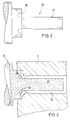
- Fig. 2 is an inventive device for forming a hole surrounded by a collar in a plastic deformable wall shown, which consists essentially of a Calibration mandrel 25, which has a conical undercut Displacement collar 26 and a cylindrical calibration shaft 27 has.
- FIG. 3 shows the use of the calibration mandrel according to the invention 25 visible at the entry point of the Lubricating oil channel 16 is brought to an effect if required, calibrated passage in the manner of a throttle bore to manufacture.
- the calibration mandrel 25 is thereby axial pressure on the outer surface of the component with the Lubricant channel 16 is placed and the pressure becomes such reinforces that the displacement collar 26 through the material plastic deformation in the direction of that shown in FIG. 3 Displaced arrows, whereby a collar 28 is formed, its inside diameter through the cylindrical part of the calibration shaft 27 of the calibration mandrel 25 is determined.
- the cylindrical part of the calibration shaft ensures an exact calibrated dimensioning of the inner diameter of the collar 28 and thus for a precise definition of Flow through this narrow point.
- Throttle bores preferably in materials such as e.g. aluminum can be applied favorably where by plastic deformation is not too high and displacement of the wall material can be.
Landscapes
- Engineering & Computer Science (AREA)
- Mechanical Engineering (AREA)
- General Details Of Gearings (AREA)
Description
- Fig. 1
- einen Teilschnitt durch ein automatisches Getriebe, wo in bestimmten Bereichen Schmiermittelkanäle verlaufen, die mittels Hülseneinsätzen mit genau kalibrierten Drosselöffnungen versehen werden;
- Fig. 2
- eine Teilansicht einer erfindungsgemäßen Vorrichtung zur Bildung eines von einem Kragen umgebenen Loches und
- Fig. 3
- einen Teilschnitt durch den Bereich im Kreis III in Fig. 1 wo an Stelle der bisher bekannten Hülse mit Drosselbohrung die erfindungsgemäße Ausbildung einer Drosselbohrung aufgezeigt ist.
Claims (1)
- Vorrichtung zum Bilden eines von einem Kragen (28) umgebenen, kalibrierten Loches in einer plastisch verformbaren Wandung, die mit einer vorgefertigten Bohrung (16) mittleren Durchmessers versehen ist, mittels eines unter Druckeinwirkung in die Wandung eingetriebenen Dornes, dadurch gekennzeichnet, daßder Dorn als ein Kalibrierdorn (25) mit einem kegelförmig hinterschnittenen Verdrängungskragen (26) von größerem Durchmesser als die Bohrung (16) und mit einem zylindrischen Teil eines Kalibrierschaftes (27) von kleinerem Durchmesser als die Bohrung (16) ausgebildet ist, wobei der Verdrängungskragen (26) beim Eintreiben des Dornes in die Wandung das Material durch plastisches Verformen in Richtung des Kalibrierschaftes (27) verdrängt.
Applications Claiming Priority (2)
| Application Number | Priority Date | Filing Date | Title |
|---|---|---|---|
| DE19534790 | 1995-09-20 | ||
| DE19534790A DE19534790A1 (de) | 1995-09-20 | 1995-09-20 | Vorrichtung zum Bilden eines von einem Kragen umgebenen Loches in plastisch verformbaren Wandungen |
Publications (2)
| Publication Number | Publication Date |
|---|---|
| EP0764481A1 EP0764481A1 (de) | 1997-03-26 |
| EP0764481B1 true EP0764481B1 (de) | 1998-07-29 |
Family
ID=7772600
Family Applications (1)
| Application Number | Title | Priority Date | Filing Date |
|---|---|---|---|
| EP96114587A Expired - Lifetime EP0764481B1 (de) | 1995-09-20 | 1996-09-12 | Vorrichtung zum Bilden eines von einem Kragen umgebenen, kalibrierten Loches in plastisch verformbaren Wandungen |
Country Status (2)
| Country | Link |
|---|---|
| EP (1) | EP0764481B1 (de) |
| DE (2) | DE19534790A1 (de) |
Families Citing this family (3)
| Publication number | Priority date | Publication date | Assignee | Title |
|---|---|---|---|---|
| DE19803366A1 (de) * | 1998-01-29 | 1999-08-05 | Bosch Gmbh Robert | Gehäuseblock |
| DE10064847C1 (de) * | 2000-12-23 | 2002-08-22 | Wetzel Ag Sisseln Sisseln | Verfahren und Vorrichtung zum Vermessen und gegebenenfalls Kalibrieren einer Lochung eines Werkstücks |
| EP4083509B1 (de) * | 2021-04-30 | 2024-12-25 | Ansaldo Energia Switzerland AG | Verfahren zur kalibrierung eines gasturbinenbrenners während der überholung oder herstellung unter verwendung eines kalibrierungsstifts |
Family Cites Families (3)
| Publication number | Priority date | Publication date | Assignee | Title |
|---|---|---|---|---|
| DE2127696A1 (de) * | 1971-06-04 | 1973-02-01 | Waeschle Maschf Gmbh | Verfahren und werkzeug zum befestigen von stiftschrauben od.dgl. in sackloechern in relativ duennen platten, insbesondere buegeleisenplatten |
| NL7700871A (nl) * | 1977-01-27 | 1978-07-31 | Geffen Tech Adviesbureau Bv | Werkwijze en inrichting voor het door wrij- vingswarmte en druk maken van een door een kraag omgeven gat in metalen plaat of de wand van een metalen buis. |
| JPS6174735A (ja) * | 1984-09-17 | 1986-04-17 | Aisin Seiki Co Ltd | 金属板のバ−リング加工方法 |
-
1995
- 1995-09-20 DE DE19534790A patent/DE19534790A1/de not_active Withdrawn
-
1996
- 1996-09-12 EP EP96114587A patent/EP0764481B1/de not_active Expired - Lifetime
- 1996-09-12 DE DE59600377T patent/DE59600377D1/de not_active Expired - Fee Related
Also Published As
| Publication number | Publication date |
|---|---|
| EP0764481A1 (de) | 1997-03-26 |
| DE59600377D1 (de) | 1998-09-03 |
| DE19534790A1 (de) | 1997-03-27 |
Similar Documents
| Publication | Publication Date | Title |
|---|---|---|
| DE69725150T2 (de) | Drehmomenttragendes element in einer schaltkupplung | |
| DE4302844C1 (de) | Planetenradträger-Anordnung mit einer ringförmigen Ölstauscheibe | |
| DE2124009C3 (de) | Aus Blechteilen gefertigter Planetenradträger für ein Planetenradgetriebe | |
| DE2937471C2 (de) | Automatisches Getriebe mit einer ersten und einer zweiten Kupplung | |
| DE3743976C3 (de) | Vorrichtung zur Drehmomentübertragung | |
| WO2001007762A1 (de) | Hohlwelle mit innenkanälen, insbesondere ölkanälen | |
| DE10333879A1 (de) | Planetenträger für Getriebe | |
| DE102012218357A1 (de) | Verfahren zum Herstellen eines Kombinationszahnrads für einen gestapelten Planetenradsatz | |
| DE102009048377B4 (de) | Verfahren zum Herstellen von Lamellen einer Reibkupplung | |
| EP1950442A1 (de) | Doppelkupplung eines Doppelkupplungs-Getriebes | |
| DE69101574T2 (de) | Leistungsgetriebe. | |
| DE3245840C2 (de) | Vorrichtung zur Zuführung von Hydraulikflüssigkeit zu mindestens einer hydraulisch betätigten Kupplung | |
| EP0969219A2 (de) | Kupplungsscheibe | |
| DE2903469A1 (de) | Platte o.dgl. mit gerippter oeffnung fuer einen mit pressitz einzufuegenden bauteil wie lager | |
| DE19928569C2 (de) | Vorrichtung und Verfahren zum Montieren eines Toroidgetriebes mit stufenlos veränderbarer Übersetzung | |
| EP0683876B1 (de) | Einrichtung zur führung einer beweglichen scheibe | |
| DE19705513C2 (de) | Riemenscheibenvorrichtung eines stufenlos variablen Getriebes und Verfahren zur Herstellung derselben | |
| EP0764481A1 (de) | Vorrichtung zum Bilden eines von einem Kragen umgebenen, kalibrierten Loches in plastisch verformbaren Wandungen | |
| EP1316746A2 (de) | Automatgetriebe | |
| EP0253380A2 (de) | Planetenräder-Wechselgetriebe in Form eines Simpson-Satzes | |
| EP1686277A1 (de) | Doppelkupplung mit gleichgrossen Lamellen | |
| DE3022958A1 (de) | Keilwellenkupplung | |
| DE102006044890A1 (de) | Kompakter Öltransferkrümmer | |
| DE102023205470B3 (de) | Lamellenträger für ein Lamellenschaltelement | |
| DE3242055C2 (de) | Vorrichtung zum Verbinden und Zusammenhalten zweier Wellenteilstücke, insbesondere einer Nockenwelle, während eines hydraulischen Schrumpfvorganges |
Legal Events
| Date | Code | Title | Description |
|---|---|---|---|
| PUAI | Public reference made under article 153(3) epc to a published international application that has entered the european phase |
Free format text: ORIGINAL CODE: 0009012 |
|
| AK | Designated contracting states |
Kind code of ref document: A1 Designated state(s): DE FR GB |
|
| 17P | Request for examination filed |
Effective date: 19970418 |
|
| GRAG | Despatch of communication of intention to grant |
Free format text: ORIGINAL CODE: EPIDOS AGRA |
|
| RAP1 | Party data changed (applicant data changed or rights of an application transferred) |
Owner name: FORD FRANCE S. A. Owner name: FORD MOTOR COMPANY LIMITED Owner name: FORD-WERKE AKTIENGESELLSCHAFT |
|
| RAP1 | Party data changed (applicant data changed or rights of an application transferred) |
Owner name: FORD FRANCE S. A. Owner name: FORD MOTOR COMPANY LIMITED Owner name: FORD-WERKE AKTIENGESELLSCHAFT |
|
| 17Q | First examination report despatched |
Effective date: 19970908 |
|
| GRAG | Despatch of communication of intention to grant |
Free format text: ORIGINAL CODE: EPIDOS AGRA |
|
| GRAH | Despatch of communication of intention to grant a patent |
Free format text: ORIGINAL CODE: EPIDOS IGRA |
|
| GRAH | Despatch of communication of intention to grant a patent |
Free format text: ORIGINAL CODE: EPIDOS IGRA |
|
| GRAA | (expected) grant |
Free format text: ORIGINAL CODE: 0009210 |
|
| AK | Designated contracting states |
Kind code of ref document: B1 Designated state(s): DE FR GB |
|
| GBT | Gb: translation of ep patent filed (gb section 77(6)(a)/1977) |
Effective date: 19980729 |
|
| REF | Corresponds to: |
Ref document number: 59600377 Country of ref document: DE Date of ref document: 19980903 |
|
| RAP2 | Party data changed (patent owner data changed or rights of a patent transferred) |
Owner name: FORD GLOBAL TECHNOLOGIES, INC. |
|
| ET | Fr: translation filed | ||
| PLBE | No opposition filed within time limit |
Free format text: ORIGINAL CODE: 0009261 |
|
| STAA | Information on the status of an ep patent application or granted ep patent |
Free format text: STATUS: NO OPPOSITION FILED WITHIN TIME LIMIT |
|
| 26N | No opposition filed | ||
| REG | Reference to a national code |
Ref country code: FR Ref legal event code: TP Ref country code: FR Ref legal event code: CD |
|
| REG | Reference to a national code |
Ref country code: GB Ref legal event code: IF02 |
|
| REG | Reference to a national code |
Ref country code: GB Ref legal event code: 732E |
|
| PGFP | Annual fee paid to national office [announced via postgrant information from national office to epo] |
Ref country code: GB Payment date: 20030827 Year of fee payment: 8 |
|
| PGFP | Annual fee paid to national office [announced via postgrant information from national office to epo] |
Ref country code: DE Payment date: 20030903 Year of fee payment: 8 |
|
| PGFP | Annual fee paid to national office [announced via postgrant information from national office to epo] |
Ref country code: FR Payment date: 20030904 Year of fee payment: 8 |
|
| PG25 | Lapsed in a contracting state [announced via postgrant information from national office to epo] |
Ref country code: GB Free format text: LAPSE BECAUSE OF NON-PAYMENT OF DUE FEES Effective date: 20040912 |
|
| PG25 | Lapsed in a contracting state [announced via postgrant information from national office to epo] |
Ref country code: DE Free format text: LAPSE BECAUSE OF NON-PAYMENT OF DUE FEES Effective date: 20050401 |
|
| GBPC | Gb: european patent ceased through non-payment of renewal fee |
Effective date: 20040912 |
|
| PG25 | Lapsed in a contracting state [announced via postgrant information from national office to epo] |
Ref country code: FR Free format text: LAPSE BECAUSE OF NON-PAYMENT OF DUE FEES Effective date: 20050531 |
|
| REG | Reference to a national code |
Ref country code: FR Ref legal event code: ST |