EP0760772B1 - Fahrradrahmen aus verbundwerkstoff, verfahren zu seiner herstellung und form dafür - Google Patents
Fahrradrahmen aus verbundwerkstoff, verfahren zu seiner herstellung und form dafür Download PDFInfo
- Publication number
- EP0760772B1 EP0760772B1 EP95920942A EP95920942A EP0760772B1 EP 0760772 B1 EP0760772 B1 EP 0760772B1 EP 95920942 A EP95920942 A EP 95920942A EP 95920942 A EP95920942 A EP 95920942A EP 0760772 B1 EP0760772 B1 EP 0760772B1
- Authority
- EP
- European Patent Office
- Prior art keywords
- tube
- mold
- seat
- axis
- bicycle frame
- Prior art date
- Legal status (The legal status is an assumption and is not a legal conclusion. Google has not performed a legal analysis and makes no representation as to the accuracy of the status listed.)
- Expired - Lifetime
Links
Images


Classifications
-
- B—PERFORMING OPERATIONS; TRANSPORTING
- B62—LAND VEHICLES FOR TRAVELLING OTHERWISE THAN ON RAILS
- B62K—CYCLES; CYCLE FRAMES; CYCLE STEERING DEVICES; RIDER-OPERATED TERMINAL CONTROLS SPECIALLY ADAPTED FOR CYCLES; CYCLE AXLE SUSPENSIONS; CYCLE SIDECARS, FORECARS, OR THE LIKE
- B62K19/00—Cycle frames
- B62K19/02—Cycle frames characterised by material or cross-section of frame members
- B62K19/16—Cycle frames characterised by material or cross-section of frame members the material being wholly or mainly of plastics
-
- B—PERFORMING OPERATIONS; TRANSPORTING
- B29—WORKING OF PLASTICS; WORKING OF SUBSTANCES IN A PLASTIC STATE IN GENERAL
- B29C—SHAPING OR JOINING OF PLASTICS; SHAPING OF MATERIAL IN A PLASTIC STATE, NOT OTHERWISE PROVIDED FOR; AFTER-TREATMENT OF THE SHAPED PRODUCTS, e.g. REPAIRING
- B29C33/00—Moulds or cores; Details thereof or accessories therefor
- B29C33/30—Mounting, exchanging or centering
- B29C33/308—Adjustable moulds
-
- B—PERFORMING OPERATIONS; TRANSPORTING
- B29—WORKING OF PLASTICS; WORKING OF SUBSTANCES IN A PLASTIC STATE IN GENERAL
- B29C—SHAPING OR JOINING OF PLASTICS; SHAPING OF MATERIAL IN A PLASTIC STATE, NOT OTHERWISE PROVIDED FOR; AFTER-TREATMENT OF THE SHAPED PRODUCTS, e.g. REPAIRING
- B29C70/00—Shaping composites, i.e. plastics material comprising reinforcements, fillers or preformed parts, e.g. inserts
- B29C70/04—Shaping composites, i.e. plastics material comprising reinforcements, fillers or preformed parts, e.g. inserts comprising reinforcements only, e.g. self-reinforcing plastics
- B29C70/28—Shaping operations therefor
- B29C70/40—Shaping or impregnating by compression not applied
- B29C70/42—Shaping or impregnating by compression not applied for producing articles of definite length, i.e. discrete articles
- B29C70/46—Shaping or impregnating by compression not applied for producing articles of definite length, i.e. discrete articles using matched moulds, e.g. for deforming sheet moulding compounds [SMC] or prepregs
- B29C70/48—Shaping or impregnating by compression not applied for producing articles of definite length, i.e. discrete articles using matched moulds, e.g. for deforming sheet moulding compounds [SMC] or prepregs and impregnating the reinforcements in the closed mould, e.g. resin transfer moulding [RTM], e.g. by vacuum
-
- B—PERFORMING OPERATIONS; TRANSPORTING
- B29—WORKING OF PLASTICS; WORKING OF SUBSTANCES IN A PLASTIC STATE IN GENERAL
- B29D—PRODUCING PARTICULAR ARTICLES FROM PLASTICS OR FROM SUBSTANCES IN A PLASTIC STATE
- B29D12/00—Producing frames
-
- B—PERFORMING OPERATIONS; TRANSPORTING
- B62—LAND VEHICLES FOR TRAVELLING OTHERWISE THAN ON RAILS
- B62K—CYCLES; CYCLE FRAMES; CYCLE STEERING DEVICES; RIDER-OPERATED TERMINAL CONTROLS SPECIALLY ADAPTED FOR CYCLES; CYCLE AXLE SUSPENSIONS; CYCLE SIDECARS, FORECARS, OR THE LIKE
- B62K19/00—Cycle frames
- B62K19/18—Joints between frame members
- B62K19/22—Adhesive joints
-
- B—PERFORMING OPERATIONS; TRANSPORTING
- B29—WORKING OF PLASTICS; WORKING OF SUBSTANCES IN A PLASTIC STATE IN GENERAL
- B29C—SHAPING OR JOINING OF PLASTICS; SHAPING OF MATERIAL IN A PLASTIC STATE, NOT OTHERWISE PROVIDED FOR; AFTER-TREATMENT OF THE SHAPED PRODUCTS, e.g. REPAIRING
- B29C33/00—Moulds or cores; Details thereof or accessories therefor
- B29C33/44—Moulds or cores; Details thereof or accessories therefor with means for, or specially constructed to facilitate, the removal of articles, e.g. of undercut articles
- B29C33/48—Moulds or cores; Details thereof or accessories therefor with means for, or specially constructed to facilitate, the removal of articles, e.g. of undercut articles with means for collapsing or disassembling
Definitions
- the invention relates to a bicycle frame made of material composite, like those that include a connected down tube, by a bottom bracket, a seat tube and two extending bases towards the rear, moving away from the bottom bracket, a shroud rear connecting the ends of the bases to an upper part of the tube saddle, and an upper longitudinal tube connecting the saddle tube to a head tube, which connects this longitudinal tube and the upper end of the down tube.
- Bicycle frames made of composite material i.e. material based on carbon free or equivalent free, present the advantage of a significant reduction in weight.
- the current composite material frames are divided into practical, in two main families, namely the monohull frames and frames with composite fittings or aluminum fittings.
- Monohull frames are made by molding in a single piece, or possibly by overmolding of two parts made in prior.
- This manufacturing process requires a large number tools so as to be able to cover the entire demand customer base ; a minimum of twelve sizes seems necessary for a product of this level of range, in order to satisfy the range of body types of cyclists.
- the concept of the monocoque frame is penalizing for the product itself.
- the molding operation is carried out with a lost core, usually made of polyurethane or foam material equivalent.
- the overweight imposed by the molding core that remains inside the frame tubes is a significant drawback since it goes against reducing the weight of the frame.
- inflatable cores are used during molding to avoid cores lost, but the implementation of such inflatable cores is tricky; moreover, the molding quality is insufficient and requires an additional cost of finish.
- the frames with composite fittings constituting the second family mentioned above, are made so conventional.
- Tubular elements made of composite material are assembled by gluing on junction fittings.
- the fittings are made of composite material which allows significant weight savings compared to fitting models traditional aluminum.
- the object of the invention is, above all, to remedy the drawbacks of the two main families of composite frames mentioned above.
- the invention aims, in particular, to provide a frame of material composite that is as rigid as possible and particularly reliable and robust, while remaining of an acceptable manufacturing cost.
- a bicycle frame made of composite material is characterized by the fact that it comprises a first sub-assembly molded in a single block constituted at the less down tube, bottom bracket, seat tube, two bases and the lower part of the head tube, and one second self-molded sub-assembly consisting of the tube longitudinal upper, saddle connection and upper part of the head tube, the meeting of these two sub-assemblies being made by collage.
- the down tube, the seat tube and the tube longitudinal upper are devoid of any molding core to the interior.
- the rear shroud is generally a third subset integrally molded with the upper end connected by gluing to a guy fitting provided on the seat tube and of which each lower end is connected to a lug itself connected to the rear part of a base.
- the bicycle frame comprises a socket connection, engaged in the two composite material parts of the head tube, these two parts being applied end to end and glued to the connecting sleeve and between them.
- the connecting sleeve used to assemble the two parts in composite material of the head tube, is preferably made in two nested pieces glued. Each piece of the connecting sleeve may have at its outer end a collar forming a bearing diameter larger than that of the composite material bushing.
- the invention also relates to molds for producing a composite material frame according to the invention.
- a first mold to make the first subset of the frame, consists of two half-molds applying one against the other along a joint plane passing through the axis of the down tube and the axis of the seat tube, and is characterized by the fact that each half-mold includes two elements assembled, in a removable manner, along a junction plane orthogonal to the plane of the axis of the down tube and the axis of the seat tube and passing through the axis of the bottom bracket, a first element of the half-mold comprising a tube imprint saddle and a basic footprint provided at the bottom of a clean recess to receive a core, combined with the recess, which core comprises a basic footprint associated with that of the recess, while second element of the half-mold has a tube imprint diagonal and bottom of head tube, the mold allowing to mold a group of first frame sub-assemblies of different dimensions by changing only the model of second element of the half-mold.
- the first element of the half-mold comprises a seat tube imprint corresponding to the maximum length seat tube possible for group of material frames composite intended to be manufactured with this first element and with several models of second half-mold element.
- the mold for the production of the second sub-assembly of the frame also consists of two half-molds applied in a joint plane passing through the axis of the upper longitudinal tube and through the axis of the head tube and the seat fitting, and is characterized in fact each half-mold has two parts corresponding to each end of the upper longitudinal tube with respectively the upper part of the head tube and the seat connection, and a spacer located between these two parts, this spacer having a variable dimension, along the direction of the axis of the upper longitudinal tube to allow the length to be varied of this tube.
- the rear shroud constituting the third sub-assembly of the frame, is identical on all frame models and the mold for this third subset is unique.
- the invention also relates to a method of molding a bicycle frame as defined above, characterized by the fact that the first sub-assembly is molded in a single block in using molding mandrels for the lower part of the socket steering, down tube, seat tube, bottom bracket, these mandrels being able to be released later, and a core rigid foam lost for the bases, which is molded in a single block the longitudinal upper tube with the seat fitting and the part upper of the head tube, using clean mandrels to be released later, that we mold in a single block the shroud rear, and that the various sub-assemblies are assembled by gluing of the frame, after withdrawal of the above mandrels.
- the seat tube mandrel fits at its end lower, in the bottom bracket mandrel, as well as the rigid foam cores lost for the bases.
- the fitting mandrel seat stays in the seat tube mandrel.
- the chuck of the lower part of the head tube receives the upper end down tube mandrel.
- This mandrel of the down tube can, according to a first possibility, cross the mandrel of the bottom bracket so as to be extracted through this bottom bracket mandrel.
- the mandrel of the down tube does not open into the housing bottom bracket and it is only after molding that the material zones composite of the bottom bracket, located in alignment with the mandrel of the down tube, are drilled to allow the extraction of this down tube mandrel.
- the invention consists, apart from the arrangements set out above, in a number of other provisions which it will be more explicit question below about an example described with reference to the attached drawings, but which is by no means limiting.
- Figure 1 of these drawings is a schematic elevational view showing the three monoblock sub-assemblies of a frame according to the invention, before assembly.
- Figure 2 shows, similarly to Figure 1, the frame made after assembly of the three sub-assemblies.
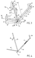
- FIG. 3 is a schematic plan view of a half-mold, with its two elements, for the realization of the first sub-assembly.
- Figure 4 is an elevational view of the nested mandrels, dressing course with composite material, for molding subsequent of the first subset.
- Figure 5 is a section, on a larger scale, along the line V-V figure 3 of the two half-molds applied one against the other.
- Figure 6 is a section along line VI-VI, Figure 3 to more large scale, two half-molds applied one against the other.
- Figure 7 is a plan view of the half-mold for the second subset.
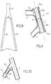
- Figure 8 is an elevational view of the rear shroud.
- Figure 9 is an axial section, on a larger scale, illustrating the assembly of the steering bush.
- Figure 10 is a partial axial section, illustrating the assembly of the shroud fitting and the rear shroud.
- Frame C comprises a first sub-assembly A molded of single block consisting of down tube 1, bottom bracket 2, tube saddle 3, of the two bases 4 which extend rearward, while deviating, from the bottom bracket 2 and the lower part 5 of the socket direction D.
- the frame includes a second sub-assembly B molded from single block and consisting of the upper longitudinal tube 6, a connection of seat 7 and upper part 8 of the steering bush.
- the tube upper 6, in the example considered, is a horizontal tube; this tube could however be tilted in particular from top to bottom of the fitting from seat 7 to the steering socket.
- a third self-molded H sub-assembly is formed by the rear shroud 9 comprising, as visible in FIG. 8, two arms 10 forming a sort of rear fork, connected to their the upper end to a single stronger tubular element 11 diameter.
- the seat tube 3 is provided with a seat fitting 12, the position relative to the bases and the steering box 2 remains constant.
- the rear shroud 9 remains identical.
- the area f located above the fitting 12 which may vary in length.
- Parts 5 and 8 of the steering bush in composite material will also vary in length in areas cylindrical g and j, in connection with the length variations in the zone f.
- this guy could alternatively be molded in one piece with the first subset A.
- the axis of the seat tube 3 is substantially parallel, or is parallel to the axis of the steering socket D, so that a combined height variation of area f on the one hand and areas j, g on the other hand, does not cause a significant change in length of the tube longitudinal superior 6.
- the variation in length caused by a variation in height of area f is of the order of a few tenths millimeters which can be caught up by machining, without having to change the tube 6.
- the three subsets are brought together by gluing.
- the assembly of the lower part 5 and the upper part 8 of the composite material head tube is produced, as illustrated in FIG. 9, using a connecting sleeve 13, for example metallic or composite material.
- This socket 13 is made of two parts 13a, 13b, cylindrical, fitted at their ends located at inside the frame. Each piece 13a, 13b of the socket comprises at its outer end a collar respectively 14a, 14b, forming a bearing, of diameter greater than that of the parts 8, 5 in composite material of the socket. Parts 13a, 13b are adjusted to enter parts 5, 8 made of composite material with play necessary for an adhesive film. Parts 13a, 13b are assembled between them by gluing at their nesting. Parts 5 and 8 of composite material are applied end to end and are glued to the external surface of the parts 13a, 13b and between them. The assembly thus produced is particularly reliable.
- FIG. 10 illustrates the assembly of the tubular element 11 of the rear shroud 9 and of the shroud fitting 12 provided in the upper part of the seat tube 3.
- the tubular connection 12 and the element 11 have the same internal diameter and same external diameter.
- a sleeve 15, engaged without play substantially over half of its length in the connector 12 and in element 11, is glued to these two elements placed end to end and also glued together.
- Tubes 1, 3 and 6 are hollow and devoid of any
- Bases 4 have a core of lost molding, for example in polyurethane, the weight of which is very reduced due to the reduced internal volume of these bases 4. The same is true for even at the branches 10 of the shroud 9 which may have a lost polyurethane foam core, without the weight of the frame be changed significantly.
- FIG. 3 illustrates a half-mold 17 for molding the first subset A.
- the complete Ma mold to achieve this first sub-assembly A, consists of two half-molds 17, 17 ' (see figures 4 and 5) applying one against the other according to a plane of joint Q passing through the axis of down tube 1 and seat tube 3.
- the half-mold 17 ′ conjugated with the half-mold 17 shown in FIG. 3 is symmetrical of the latter with respect to the joint plane Q.
- the parts of the mold 17 ' will be designated by the same reference numerals affected by the sign '.
- the opening of the mold Ma is carried out by spreading the two half-molds 17, 17 'on either side of the plane Q.
- the half-mold 17 comprises two supporting elements 18, 19 along a junction plane P orthogonal to the plane of the geometric axes y1, y3 of the down tube and the seat tube.
- plan P is orthogonal to the plane of Figure 3.
- the elements 18, 19 are mechanically assembled to each other, in a removable manner.
- Element 18 substantially in the form of a right angle turning its concavity towards the rear, has a seat tube imprint 20.
- This imprint 20 corresponds to a semi-cylindrical cavity and to the half-section of the seat tube 3.
- the imprint 20 comprises a kind of stump 21 corresponding to the half-cavity of the fitting 12 of guy line.
- the upper end of the imprint 20 is extended by a housing 22 coaxial, of smaller dimension, intended to receive the upper end of a mandrel 23 visible in FIG. 4.
- the imprint 21 is extended, downwards, by a housing 24, coaxial, of smaller dimension intended to receive the lower end of a mandrel 25 (FIG. 4) for the connection of guy 12.
- the mandrels 23 and 25, as well as the other mandrels which will be discussed below, are removable metal mandrels which can be released by withdrawal tubes after molding.
- the mandrels could be made of any other material, especially in a material capable of being eliminated for example by dissolution or fusion, after molding of the tubes.
- a material capable of being eliminated for example by dissolution or fusion after molding of the tubes.
- the length 1 of the imprint 20 taken between the upper end of this imprint and the geometric axis of the bottom bracket corresponds to the maximum length of the seat tube of a group of frames of different sizes intended to be produced using the mold Ma.
- the frame produced corresponds to a seat tube size 3 less than length 1, just cut this tube to its upper end, above the guy fitting 12, to the length desired.
- the mold element 18 has a sectioned recess 26 transverse substantially in open V, as visible in Figure 5.
- the two faces of the recess 26 are planar.
- an imprint 27 corresponding to the half-section of a base 4.
- the recess 26 is intended to receive the half-section of a core 28 ( Figure 5) whose cross section through a section plane orthogonal to the plane of the geometric axes of the bases 4 has substantially the diamond shape.
- the other half-section of the core 28 is received in the recess 26 'of the element 18' of the other half-mold 17 '.
- the core 28 has imprints 29, 29 'combined with imprints 27, 27' for molding the bases 4.
- Figure 6 which corresponds to a section of the mold and the core along the plane of the geometric axes of the bases, shows the triangular wedge shape of the core 28 whose transverse dimension gradually increases from the area near the bottom bracket to the back of the bases.
- the lower part of the imprint 20 and the front part of the imprint 27 lead into an imprint 30 (see Figure 3) for the molding of the bottom bracket 2.
- This imprint 30 is connected to a cylindrical housing 31 (see FIG. 6) whose axis, perpendicular in the plane of Figure 3, passes through the intersection of the geometric axes y1 and y3.
- This housing 31 is crossed by the junction plane P so a semi-cylindrical cavity is located in the element 18 and the cavity is located in element 19.
- a housing 32 coaxial with the axis y1 of the seat tube, opens into the imprint 30 and extends from side opposite to element 19.
- This housing 32 is intended to receive the end 33 (FIG. 4) of the metal mandrel 34 for the tube diagonal 1.
- the element 19 has an imprint 35 corresponding to the half section of the down tube.
- This imprint 35 in the lower part, is connects to the footprint 30 of the bottom bracket.
- the imprint 35 opens into an imprint 36 corresponding to the half section of the lower part 5 of the steering bush.
- the end upper footprint 36 is extended by a coaxial housing 37 of smaller diameter, intended to receive the upper end of the mandrel 38 for the lower part 5 of the steering bush.
- a metal mandrel 39 ( Figure 4) is provided to engage in the housing 31.
- the mandrel 39 is crossed by a diametral hole suitable for allowing the passage of the lower end of the mandrel 34 which projects, by its end 33, on the other side.
- the mandrel 39 further comprises a housing suitable for receiving the lower end of the mandrel 23 engaged by translation along the direction of its axis in this housing of mandrel 39.
- the mandrel 39 further comprises housings suitable for receive, respectively, the end of cores 40, for example in polyurethane foam, intended for molding the bases 4.
- the cores 40 are lost and remain inside the bases 4 when they are removed from the mold; when extraction of the sleeve 39, the ends of the cores 40 engaged in the corresponding housings of the sleeve 39 are sheared.
- the mandrel 23 includes a housing in which fits the upper end of the mandrel 25, while the mandrel 38 in lower part has a housing in which fits the end upper chuck 34.
- the different mandrels 23, 25, 34, 39 and 38 are nested in each other and the cores 40 are put in place to form a framework of the first frame subset such as illustrated in figure 4.
- the mandrels are then covered with the material composite, i.e. braids 41 in carbon free or in analogous material. This skin wraps continuously the frame, especially in the areas of the bottom bracket (mandrel 39) and in the junction zones between the down tube 1 and the part 5 of the steering box.
- the blank thus prepared is then put in place for a resin injection, for example an epoxy resin, in a way conventional, as described, for example, in FR-A-2 684 062.
- the imprint 36 can be provided with the maximum height so that for the same angle it will be possible by cutting off the upper end of part 5 and seat tube 3, to make frames of different heights, but with same length of upper tube 6.
- the molding operation of the sub-assembly A is finished.
- the mandrel 34 is then removed by pulling on the lower end 33 in the axial direction.
- the mandrel 38 can then be cleared.
- the mandrel 25 is extracted, which then releases it by the up the mandrel 23 in the axial direction. It is finally possible extract the mandrel 39 along the direction of its axis, by shearing as already indicated the ends of the cores 40 which remain in the basics 4.
- the mandrel 39 could be produced in two parts so as to facilitate its extraction.
- the element 18 can be devoid of housing 32, while the mandrel 34 has a shorter length than that shown in Figure 4, so as to stop before reaching the mandrel 39 in which it is not fitted.
- the mandrel 25 is first extracted, then the mandrel 23; the mandrel 39 can then be extracted, with shearing of the ends of the cores 40, since the mandrel 34 no longer penetrates into the mandrel 39.
- the bottom bracket 2 is obtained with a peripheral wall keep on going.
- a diametral hole is drilled in the wall of the housing 2, in alignment with the mandrel 34 which can then be extracted by axial sliding downwards.
- the box area 2 where is made the hole for the passage of the mandrel 34 is only weakly mechanically stressed, so that the resistance of the frame is not affected.
- FIG. 7 illustrates in plan a half-mold 41 for manufacturing of the second subset B.
- the mold for the production of the second sub-assembly B is consists of the half-mold 41 visible in FIG. 7 and a second half-mold applied to the first along a joint plane passing through the geometric axis y6 of the upper tube 6 and by the geometric axes y8 and y7 of part 8 of the head tube and the connection saddle 7.
- the half-mold 41 is made up of two end parts 42, 43 and a spacer 44, all of these elements having the form of rectangular parallelepipeds.
- the joint plans between the spacer 44 and the end parts 42, 43 are orthogonal to the axis y6.
- the end part 42 has a semi-cylindrical cavity 45 corresponding to the half-section of the rear part of the tube upper 6.
- This imprint 45 opens into a cavity 46 corresponding to the half-section of the seat connector 7.
- a housing 47 extends coaxially to the imprint 45, on the side opposite this imprint to receive the end of a metal mandrel, not shown, corresponding to the interior volume of tube 6.
- the other mold part 43 has an imprint 48 corresponding to the half-section of the front area of the upper tube 6.
- the imprint 48 leads, at its front end, into an imprint 49 corresponding to the half-section of the upper part 8 of the steering socket.
- imprint 46 As in imprint 47, open out, along the direction of the axis of each imprint, and at each end, housings respectively 50, 51 for the imprint 46 and 52, 53 for the imprint 49. These housings are intended to receive the ends of removable metal mandrels, not shown, which pass through the fitting 7 and the sleeve part 8 during molding.
- the imprint 49 is closed towards the following front the y6 axis so that the molded part 8 has no opening forward.
- Seat connector 7 will have an opening corresponding to the passage of the mandrel of the tube 6.
- the spacer 44 includes an imprint 54 corresponding to a intermediate zone of the half-section of the tube 6 and ensuring the connection between cavities 45 and 48.
- the chucks, not shown, intended for the manufacture of the sub-assembly B fit together into each other.
- the extraction of the mandrel from the tube 6 will only be possible only after extracting the chuck from part 8 of the socket direction and the mandrel of the connector 7.
- one or more other models of elements can be provided 18 and parts 42, 43, in which, in particular, the angles of inclination of the geometric axes y3 y7 and y8 can be different.
- Each unique model of element 18 and parts 42, 43 several models of element 19 and spacer 44 will be associated.
- the invention makes it possible to produce a frame of composite material very light thanks to the absence of a lost core in the main tubes namely the down tube 1, seat tube 3 and upper tube 6.
- the bicycle frame according to the invention is very reliable and robust thanks to the reduction in the number of bondings which, moreover, located in areas with little mechanical stress.
Landscapes
- Engineering & Computer Science (AREA)
- Mechanical Engineering (AREA)
- Chemical & Material Sciences (AREA)
- Composite Materials (AREA)
- Motorcycle And Bicycle Frame (AREA)
- Moulds For Moulding Plastics Or The Like (AREA)
Claims (10)
- Fahrradrahmen aus Verbundmaterial mit einem Diagonalrohr (1), das über ein Pedalgehäuse (2) mit einem Sattelrohr (3) und zwei sich von dem Pedalgehäuse auseinanderlaufend nach hinten erstreckenden Basiselementen (4) verbunden ist, einem hinteren Holm (9), der die Enden der Basiselemente mit einem oberen Bereich des Sattelrohres verbindet, und einem oberen Langsrohr (6), das das Sattelrohr (3) mit einer Lenkbuchse (D) verbindet, welche die Verbindung zwischen dem Längsrohr (8) und dem oberen Ende des Diagonalrohres (1) herstellt, dadurch gekennzeichnet, daß der Rahmen eine erste Untereinheit (A), die als ein Block gegossen ist, aufweist und aus wenigstens dem Diagonalrohr (1), dem Pedalgehäuse (2), dem Sattelrohr (3), den beiden Basiselementen (4) und dem unteren Teil (5) der Lenkbuchse besteht, und eine zweite, als ein Block gegossene Untereinheit (B) aufweist, die aus wenigstens dem oberen Langsrohr (6), einer Sattelverbindung (7) und dem oberen Teil (8) der Lenkbuchse (D) besteht, wobei die Verbindung der beiden Untereinheiten (A, B) durch Kleben erfolgt.
- Fahrradrahmen nach Anspruch 1, dadurch gekennzeichnet, daß der hintere Holm (9) eine dritte, als ein Block gegossene Untereinheit (H) bildet, deren oberes Ende (11) durch Kleben mit einer am Sattelrohr (3) vorgesehenen Holmverbindung (12) verbunden ist und deren jeweilige untere Enden mit einer Lasche (16) verbunden sind, die ihrerseits mit dem hinteren Bereich einer Basis (4) verbunden ist.
- Fahrradrahmen nach Anspruch 1 oder 2, dadurch gekennzeichnet, daß das Diagonalrohr (1), das Sattelrohr (3) und das obere Längsrohr (6) sowie die Lenkbuchse (D) und die Sattelverbindung (7) im Inneren von jeglichem Einsatz frei sind.
- Fahrradrahmen nach einem der vorhergehenden Ansprüche, dadurch gekennzeichnet, daß er eine Verbindungsbuchse (13) aufweist, die in die beiden Teile (5, 8) der aus Verbundmaterial bestehenden Lenkbuchse (D) eingesetzt ist, wobei die beiden Teile (5, 8) endständig aneinander liegen und miteinander sowie mit der Verbindungsbuchse (13) verklebt sind.
- Fahrradrahmen nach Anspruch 4, dadurch gekennzeichnet, daß die Verbindungsbuchse (13) aus zwei miteinander verklebten zusammengesteckten Teilen (13a, 13b) besteht.
- Form (Ma) zur Herstellung der ersten Untereinheit (A) eines Fahrradrahmens nach einem der vorhergehenden Ansprüche, wobei die Form (Ma) aus zwei Formhälften (17, 17') besteht, die entlang einer Verbindungsebene (Q), die durch die Achse (y1) des Diagonalrohres und die Achse (y3) des Sattelrohres verläuft, aneinanderliegen, dadurch gekennzeichnet, daß jede Formhälfte (17, 17') zwei Elemente (18, 19; 18', 19') aufweist, die demontierbar entlang einer Verbindungsebene (P) zusammengesetzt sind, die senkrecht zur Ebene der Achse (y1) des Diagonalrohres und der Achse (y3) des Sattelrohres und durch die Achse des Pedalgehäuses (2) verläuft, wobei das erste Element (18, 18') einen Formhohlraum (20, 20') für das Sattelrohr und einen Formhohlraum (27, 27') für die Basiselemente, der am Boden einer Ausnehmung (26, 26') vorgesehen ist, welcher zur Aufnahme eines der Ausnehmung (26, 26') zugeordneten Kerns (28) geeignet ist, während das zweite Element (19, 19') der Formhälfte einen Formhohlraum (35) für das Diagonalrohr und den unteren Teil (36) der Lenkbuchse aufweist, wobei es die Form (Ma) ermöglicht, eine Gruppe von ersten Untereinheiten (A) des Rahmens mit verschiedenen Abmessungen herzustellen, indem lediglich das Modell des zweiten Elements (19) der Formhälften (17, 17') verändert wird,
- Form nach Anspruch 6, dadurch gekennzeichnet, daß das erste Element der Formhälften einen Formhohlraum für das Sattelrohr (20) aufweist, der der größtmöglichen Länge (1) des Sattelrohres für die Rahmengruppe aus Verbundmaterial entspricht, die mit diesem ersten Element (18) und mit mehreren Modellen des zweiten Elements (19) der Formhälften hergestellt werden soll.
- Form zur Herstellung der zweiten Untereinheit eines Fahrradrahmens nach einem der Ansprüche 1 bis 5, bestehend aus zwei Formhälften, die entlang einer Verbindungsebene aneinanderliegen, welche durch die Achse (y6) des oberen Längsrohres und durch die Achse (y8) der Lenkbuchse sowie die Achse (y7) der Sattelverbindung (7) verläuft, dadurch gekennzeichnet, daß jede Formhälfte zwei Teile (42, 43), die jeweils den Enden des oberen Längsrohres mit jeweils dem oberen Teil der Lenkbuchse (D) und der Saffelverbindung (7) entsprechen, und ein zwischen den beiden Teilen (42, 43) angeordnetes Zwischenstück (44) aufweist, wobei das Zwischenstück eine variable Abmessung m in Richtung der Achse (y6) des oberen Längsrohres hat, um die Veränderung der Länge dieses Rohres zu ermöglichen.
- Verfahren zum Gießen eines Fahrradrahmens nach einem der Ansprüche 1 bis 5, dadurch gekennzeichnet, daß der Blockguß der ersten Untereinheit (A) unter Verwendung von Gießdomen (38, 34, 23) für den unteren Teil der Lenkbuchse, das Diagonalrohr und das Sattelrohr, wobei die Dome zum Schluß herausziehbar sind, und eines verlorenen Kems (40) aus starrem Schaumstoff für die Basiselemente erfolgt, daß das obere Längsrohr (6) mit der Sattelverbindung (7) und dem oberen Teil (8) der Lenkbuchse als ein Block gegossen wird, indem zum Schluß herausziehbare Dorne verwendet werden, daß der hintere Holm (9) als ein Block gegossen wird, und daß die Montage durch Verkleben der Untereinheiten des Rahmens nach dem Herausziehen der Dorne erfolgt.
- Verfahren zum Gießen eines Fahrradrahmens nach Anspruch 9, dadurch gekennzeichnet, daß zur Herstellung des Rohlings des Rahmens aus Verbundmaterial vor dem Einspritzen von Kunstharz in die Form Dome (23, 25, 34, 38, 39) vorgesehen werden, die derart ineinandergreifen, daß sie Vor dem Einsetzen in die Form ein Gerüst für die erste (A) und die zweite Untereinheit (B) bilden, und anschließend das Gerüst mit Verbundmaterial verkleidet wird, wonach die Einheit zum Einspritzen des Kunstharzes in der Form angeordnet wird.
Applications Claiming Priority (3)
| Application Number | Priority Date | Filing Date | Title |
|---|---|---|---|
| FR9406681 | 1994-06-01 | ||
| FR9406681A FR2720713B3 (fr) | 1994-06-01 | 1994-06-01 | Cadre de bicyclette en matériau composite, moules pour la réalisation d'un tel cadre, et procédé de moulage du cadre. |
| PCT/FR1995/000633 WO1995032887A1 (fr) | 1994-06-01 | 1995-05-16 | Cadre de bicyclette en materiau composite, moules pour la realisation d'un tel cadre, et procede de moulage du cadre |
Publications (2)
| Publication Number | Publication Date |
|---|---|
| EP0760772A1 EP0760772A1 (de) | 1997-03-12 |
| EP0760772B1 true EP0760772B1 (de) | 1998-02-11 |
Family
ID=9463754
Family Applications (1)
| Application Number | Title | Priority Date | Filing Date |
|---|---|---|---|
| EP95920942A Expired - Lifetime EP0760772B1 (de) | 1994-06-01 | 1995-05-16 | Fahrradrahmen aus verbundwerkstoff, verfahren zu seiner herstellung und form dafür |
Country Status (5)
| Country | Link |
|---|---|
| US (1) | US5857690A (de) |
| EP (1) | EP0760772B1 (de) |
| DE (1) | DE69501619T2 (de) |
| FR (1) | FR2720713B3 (de) |
| WO (1) | WO1995032887A1 (de) |
Cited By (1)
| Publication number | Priority date | Publication date | Assignee | Title |
|---|---|---|---|---|
| DE19904545A1 (de) * | 1999-02-04 | 2000-08-17 | Fachhochschule Konstanz Inst F | Fahrradrahmen |
Families Citing this family (14)
| Publication number | Priority date | Publication date | Assignee | Title |
|---|---|---|---|---|
| DE29704863U1 (de) * | 1997-03-17 | 1997-05-22 | Gesellschaft für Innenhochdruckverfahren mbH & Co. KG, 73441 Bopfingen | Achsschwinge |
| US20030205882A1 (en) * | 2001-05-16 | 2003-11-06 | Parkin Michael James | Living hinge member and suspension |
| WO2001087697A1 (en) * | 2000-05-16 | 2001-11-22 | Cannondale Corporation | Living hinge member and suspension |
| ITBO20020215A1 (it) * | 2002-04-22 | 2003-10-22 | Biciclette Fondriest S R L | Dispositivo a stampo componibile e metodo per la realizzazione di un telaio per bicicletta e telaio cosi ottenuto |
| US20050035571A1 (en) * | 2003-03-24 | 2005-02-17 | Huck Keith Allen | Article of manufacture for a hollow one piece plastic injection molded bicycle frame and process for making same |
| US6994367B2 (en) * | 2003-07-09 | 2006-02-07 | Trek Bicycle Corporation | Metal and reinforced plastic composite bicycle frame |
| JP4519632B2 (ja) * | 2004-12-27 | 2010-08-04 | 川崎重工業株式会社 | 二輪車用のフレーム |
| US7712758B2 (en) * | 2006-08-30 | 2010-05-11 | Philip White | Bicycle frame construction |
| TW200948665A (en) * | 2008-05-22 | 2009-12-01 | Giant Mfg Co Ltd | Bicycle composite bicycle frame |
| TW201008826A (en) * | 2008-08-29 | 2010-03-01 | Composite Tech Corp | Two-piece-type bicycle frame |
| KR101491653B1 (ko) * | 2014-05-27 | 2015-02-09 | 윈엔윈(주) | 자전거의 바디 프레임 |
| DE102014224040A1 (de) * | 2014-11-25 | 2016-05-25 | Bayerische Motoren Werke Aktiengesellschaft | Verfahren zu Herstellung einer Strukturbauteilgruppe sowie Strukturbauteilgruppe |
| DE102015100950A1 (de) * | 2015-01-22 | 2016-07-28 | Otto-Von-Guericke-Universität Magdeburg | Fahrradrahmen |
| JP6648097B2 (ja) * | 2017-12-07 | 2020-02-14 | 本田技研工業株式会社 | 鞍乗り型車両のスイングアーム |
Family Cites Families (5)
| Publication number | Priority date | Publication date | Assignee | Title |
|---|---|---|---|---|
| FR2528002A1 (fr) * | 1982-06-02 | 1983-12-09 | Ramond Marcel | Cycle transformable comportant une structure de base polyvalente et des equipements |
| EP0491363B1 (de) * | 1990-12-18 | 1994-11-30 | Bridgestone Cycle Co., Ltd. | Fahrradrahmen |
| WO1993008421A1 (en) * | 1991-10-22 | 1993-04-29 | Graef Peter A | Tubes and connector and method of fabrication |
| US5271784A (en) * | 1992-12-18 | 1993-12-21 | Industrial Technology Research Institute | Method for manufacturing composite bicycle frames |
| FR2702730B1 (fr) * | 1993-03-16 | 1995-06-16 | Martin Pierre Abel | Cadre de Cycle. |
-
1994
- 1994-06-01 FR FR9406681A patent/FR2720713B3/fr not_active Expired - Fee Related
-
1995
- 1995-05-16 DE DE69501619T patent/DE69501619T2/de not_active Expired - Fee Related
- 1995-05-16 US US08/750,038 patent/US5857690A/en not_active Expired - Fee Related
- 1995-05-16 WO PCT/FR1995/000633 patent/WO1995032887A1/fr not_active Ceased
- 1995-05-16 EP EP95920942A patent/EP0760772B1/de not_active Expired - Lifetime
Cited By (1)
| Publication number | Priority date | Publication date | Assignee | Title |
|---|---|---|---|---|
| DE19904545A1 (de) * | 1999-02-04 | 2000-08-17 | Fachhochschule Konstanz Inst F | Fahrradrahmen |
Also Published As
| Publication number | Publication date |
|---|---|
| FR2720713A1 (fr) | 1995-12-08 |
| DE69501619D1 (de) | 1998-03-19 |
| DE69501619T2 (de) | 1998-09-17 |
| WO1995032887A1 (fr) | 1995-12-07 |
| FR2720713B3 (fr) | 1996-08-09 |
| US5857690A (en) | 1999-01-12 |
| EP0760772A1 (de) | 1997-03-12 |
Similar Documents
| Publication | Publication Date | Title |
|---|---|---|
| EP0760772B1 (de) | Fahrradrahmen aus verbundwerkstoff, verfahren zu seiner herstellung und form dafür | |
| CA1278589C (fr) | Fourche de bicyclette a base d'une resine renforcee par une structure textile et procede pour sa fabrication | |
| FR2832959A1 (fr) | Structure d'element de siege pour vehicule et procede de fabrication d'une telle structure | |
| FR2702730A1 (fr) | Cadre de Cycle. | |
| FR2779921A1 (fr) | Chaine ornementale | |
| LU88066A1 (fr) | Cadre de cycle | |
| EP1015301B1 (de) | Fahrradgabel | |
| FR2691942A1 (fr) | Embout encoche de montage d'axe de roues de bicyclette et procédé de fixation de cet embout. | |
| EP0081834B1 (de) | Leichtgebauter Ski mit Kern und sein Herstellungsverfahren | |
| EP2228195A1 (de) | Verfahren zur Herstellung eines lang gezogenen rohrförmigen Stücks aus Kunststoff, und zur Durchführung dieses Verfahrens eingesetzte Gussform | |
| FR2738523A1 (fr) | Cadre de bicyclette du type ouvert en composite | |
| FR2684062A1 (fr) | Fourche de bicyclette et procede de fabrication d'une telle fourche. | |
| EP1184213B1 (de) | Hinterachse für ein Kraftfahrzeug und ihr Herstellungsverfahren | |
| FR2761947A1 (fr) | Procede de fabrication d'un cadre de bicyclette | |
| EP1048581A1 (de) | Tubenförmiger Hohlkörper für pastöse Produkte und Herstellungsverfahren | |
| FR3066136B1 (fr) | Demi moule presentant une face d'assemblage cylindrique et procede de realisation | |
| EP4196388B1 (de) | Verfahren zur herstellung eines mechanischen teils, resultierendes teil und aufhängungsdreieck | |
| FR2793758A1 (fr) | Tige de selle en materiau composite pour bicyclette ou engin similaire, procede et moule pour la fabrication de la tige | |
| FR2679780A1 (fr) | Procede de fabrication d'un ski. | |
| FR2512892A1 (fr) | Jonction en matiere organique, notamment sur des tubes metalliques | |
| WO1991015319A1 (fr) | Procede et structure de moulage en cire perdue | |
| FR2720384A1 (fr) | Procédé de réalisation d'une enveloppe torique, notamment d'appui-tête pour siège de véhicule automobile. | |
| FR2642268A1 (fr) | Procede de fabrication de moules de fromagerie micro-perfores, et moule obtenu par ce procede | |
| EP1207052B1 (de) | Ziergegenstand und Verfahren zu seiner Herstellung | |
| FR2835717A1 (fr) | Manche de pinceau de maquillage et son procede de fabrication |
Legal Events
| Date | Code | Title | Description |
|---|---|---|---|
| PUAI | Public reference made under article 153(3) epc to a published international application that has entered the european phase |
Free format text: ORIGINAL CODE: 0009012 |
|
| 17P | Request for examination filed |
Effective date: 19961212 |
|
| AK | Designated contracting states |
Kind code of ref document: A1 Designated state(s): DE ES FR GB IT |
|
| GRAG | Despatch of communication of intention to grant |
Free format text: ORIGINAL CODE: EPIDOS AGRA |
|
| 17Q | First examination report despatched |
Effective date: 19970407 |
|
| GRAG | Despatch of communication of intention to grant |
Free format text: ORIGINAL CODE: EPIDOS AGRA |
|
| GRAH | Despatch of communication of intention to grant a patent |
Free format text: ORIGINAL CODE: EPIDOS IGRA |
|
| GRAH | Despatch of communication of intention to grant a patent |
Free format text: ORIGINAL CODE: EPIDOS IGRA |
|
| GRAA | (expected) grant |
Free format text: ORIGINAL CODE: 0009210 |
|
| AK | Designated contracting states |
Kind code of ref document: B1 Designated state(s): DE ES FR GB IT |
|
| PG25 | Lapsed in a contracting state [announced via postgrant information from national office to epo] |
Ref country code: GB Free format text: LAPSE BECAUSE OF FAILURE TO SUBMIT A TRANSLATION OF THE DESCRIPTION OR TO PAY THE FEE WITHIN THE PRESCRIBED TIME-LIMIT Effective date: 19980211 Ref country code: ES Free format text: THE PATENT HAS BEEN ANNULLED BY A DECISION OF A NATIONAL AUTHORITY Effective date: 19980211 |
|
| REF | Corresponds to: |
Ref document number: 69501619 Country of ref document: DE Date of ref document: 19980319 |
|
| ITF | It: translation for a ep patent filed | ||
| GBV | Gb: ep patent (uk) treated as always having been void in accordance with gb section 77(7)/1977 [no translation filed] |
Effective date: 19980211 |
|
| PLBE | No opposition filed within time limit |
Free format text: ORIGINAL CODE: 0009261 |
|
| STAA | Information on the status of an ep patent application or granted ep patent |
Free format text: STATUS: NO OPPOSITION FILED WITHIN TIME LIMIT |
|
| 26N | No opposition filed | ||
| PGFP | Annual fee paid to national office [announced via postgrant information from national office to epo] |
Ref country code: DE Payment date: 20030512 Year of fee payment: 9 |
|
| REG | Reference to a national code |
Ref country code: FR Ref legal event code: GC |
|
| PG25 | Lapsed in a contracting state [announced via postgrant information from national office to epo] |
Ref country code: DE Free format text: LAPSE BECAUSE OF NON-PAYMENT OF DUE FEES Effective date: 20041201 |
|
| PGFP | Annual fee paid to national office [announced via postgrant information from national office to epo] |
Ref country code: IT Payment date: 20060531 Year of fee payment: 12 |
|
| PGFP | Annual fee paid to national office [announced via postgrant information from national office to epo] |
Ref country code: FR Payment date: 20080328 Year of fee payment: 14 |
|
| PG25 | Lapsed in a contracting state [announced via postgrant information from national office to epo] |
Ref country code: IT Free format text: LAPSE BECAUSE OF NON-PAYMENT OF DUE FEES Effective date: 20070516 |
|
| REG | Reference to a national code |
Ref country code: FR Ref legal event code: ST Effective date: 20100129 |
|
| PG25 | Lapsed in a contracting state [announced via postgrant information from national office to epo] |
Ref country code: FR Free format text: LAPSE BECAUSE OF NON-PAYMENT OF DUE FEES Effective date: 20090602 |