EP0760436A1 - Backing plate for brake lining - Google Patents
Backing plate for brake lining Download PDFInfo
- Publication number
- EP0760436A1 EP0760436A1 EP96106748A EP96106748A EP0760436A1 EP 0760436 A1 EP0760436 A1 EP 0760436A1 EP 96106748 A EP96106748 A EP 96106748A EP 96106748 A EP96106748 A EP 96106748A EP 0760436 A1 EP0760436 A1 EP 0760436A1
- Authority
- EP
- European Patent Office
- Prior art keywords
- carrier plate
- shaped bodies
- plate according
- friction lining
- support plate
- Prior art date
- Legal status (The legal status is an assumption and is not a legal conclusion. Google has not performed a legal analysis and makes no representation as to the accuracy of the status listed.)
- Granted
Links
Images
Classifications
-
- B—PERFORMING OPERATIONS; TRANSPORTING
- B22—CASTING; POWDER METALLURGY
- B22C—FOUNDRY MOULDING
- B22C7/00—Patterns; Manufacture thereof so far as not provided for in other classes
- B22C7/005—Adjustable, sectional, expandable or flexible patterns
-
- F—MECHANICAL ENGINEERING; LIGHTING; HEATING; WEAPONS; BLASTING
- F16—ENGINEERING ELEMENTS AND UNITS; GENERAL MEASURES FOR PRODUCING AND MAINTAINING EFFECTIVE FUNCTIONING OF MACHINES OR INSTALLATIONS; THERMAL INSULATION IN GENERAL
- F16D—COUPLINGS FOR TRANSMITTING ROTATION; CLUTCHES; BRAKES
- F16D65/00—Parts or details
- F16D65/02—Braking members; Mounting thereof
- F16D65/04—Bands, shoes or pads; Pivots or supporting members therefor
- F16D65/092—Bands, shoes or pads; Pivots or supporting members therefor for axially-engaging brakes, e.g. disc brakes
-
- F—MECHANICAL ENGINEERING; LIGHTING; HEATING; WEAPONS; BLASTING
- F16—ENGINEERING ELEMENTS AND UNITS; GENERAL MEASURES FOR PRODUCING AND MAINTAINING EFFECTIVE FUNCTIONING OF MACHINES OR INSTALLATIONS; THERMAL INSULATION IN GENERAL
- F16D—COUPLINGS FOR TRANSMITTING ROTATION; CLUTCHES; BRAKES
- F16D69/00—Friction linings; Attachment thereof; Selection of coacting friction substances or surfaces
- F16D69/04—Attachment of linings
- F16D69/0408—Attachment of linings specially adapted for plane linings
-
- F—MECHANICAL ENGINEERING; LIGHTING; HEATING; WEAPONS; BLASTING
- F16—ENGINEERING ELEMENTS AND UNITS; GENERAL MEASURES FOR PRODUCING AND MAINTAINING EFFECTIVE FUNCTIONING OF MACHINES OR INSTALLATIONS; THERMAL INSULATION IN GENERAL
- F16D—COUPLINGS FOR TRANSMITTING ROTATION; CLUTCHES; BRAKES
- F16D69/00—Friction linings; Attachment thereof; Selection of coacting friction substances or surfaces
- F16D69/04—Attachment of linings
- F16D2069/0425—Attachment methods or devices
- F16D2069/0441—Mechanical interlocking, e.g. roughened lining carrier, mating profiles on friction material and lining carrier
-
- F—MECHANICAL ENGINEERING; LIGHTING; HEATING; WEAPONS; BLASTING
- F16—ENGINEERING ELEMENTS AND UNITS; GENERAL MEASURES FOR PRODUCING AND MAINTAINING EFFECTIVE FUNCTIONING OF MACHINES OR INSTALLATIONS; THERMAL INSULATION IN GENERAL
- F16D—COUPLINGS FOR TRANSMITTING ROTATION; CLUTCHES; BRAKES
- F16D69/00—Friction linings; Attachment thereof; Selection of coacting friction substances or surfaces
- F16D69/04—Attachment of linings
- F16D2069/0425—Attachment methods or devices
- F16D2069/0483—Lining or lining carrier material shaped in situ
Definitions
- the invention relates to a carrier plate, in particular for motor vehicle brakes, which has, on the side bearing the friction lining, interacting with the friction lining, force and form-fitting molded bodies with undercuts.
- Friction linings of motor vehicle brakes are arranged on a carrier plate made of metallic material.
- the carrier plate is usually made of steel or alloy steel.
- the friction lining is preferably firmly connected to the carrier plate via an adhesive layer.
- openings can be provided in EP 0 163 030 in the carrier plate, in which extensions of the friction lining are arranged.
- the disadvantage of this construction is that moisture can penetrate through the openings, so that corrosion can creep from these openings, which leads to rusting of the friction linings. Correct functioning of the brake is then no longer guaranteed.
- DE 41 38933 A1 discloses a carrier plate of this type.
- the mounting bed consists of spherical shaped bodies sintered onto the carrier plate, which form undercuts in the fastening area.
- a closed metallic coating is provided over the moldings, which can consist of copper, silver, tin, cadmium or another material.
- the production of such a carrier plate requires a large number of work steps in order to connect the large number of different materials to one another.
- the invention has for its object to improve a generic carrier plate with a view to economical production and its functional properties.
- the carrier plate consists of a gray cast iron material and the molded bodies are cast in one piece. In this way it is possible to form the shaped bodies provided with undercuts in one work step.
- the load on the carrier plate is a combination of mechanical and thermal stress, whereby each type of stress leads to contradictory design principles. While the mechanical load requires large material thicknesses, the thermal load requires exactly the opposite in order to keep the temperature gradients low and thus to keep the thermal stresses within permissible limits. So far, steel has been the classic material for core boards.
- the carrier plate according to the invention preferably consists of cast iron with spheroidal graphite (GGG) or of cast iron with lamellar graphite (GGL).
- the shaped bodies can be designed as round or angular, nub-shaped elevations. It is also conceivable to design the shaped bodies as straight or curved strips.
- the surface carrying the molded body can be axially set back, so that the friction lining is optimally secured against shear forces.
- a casting mold which is formed from loose molding material is used to produce the carrier plates. The sand casting process is particularly suitable here.
- the casting mold is formed by a model of the carrier plate, which is provided with elastomeric shaped bodies which form the undercuts only under the action of the pressing pressure during the compression of the molding material.
- This compression molding process can be used to create casting molds which do not have to be cured at high temperatures. The wear of the model is largely reduced, so that economical mass production of carrier plates is possible.
- the carrier plate (1) shown in FIG. 1 consists of a gray cast iron material of the quality GGG or GGL.
- the carrier plate (1) is produced using the sand casting process and has knob-shaped molded bodies (3) on the surface (2).
- the friction lining, not shown, is pressed onto the molded body and clings to it.
- the moldings have an undercut, which increases the adhesion between the friction lining and the carrier plate (1).
- the surface structure is formed from cylindrical (3 ') shaped bodies (FIG. 2) or cube-shaped shaped bodies (3) (FIG. 1).
- the model (4) of the carrier plate (1) shown in FIGS. 3 and 4 is used as a mold model.
- the model (4) has elastomeric shaped bodies (3'').
- the molding material loose sand
- the molding sand deforms the elastomeric shaped bodies (3 ′′) during compression, as shown in FIG. 4.
- the inclined position of the elastomeric molded body (3 '') creates an undercut (5).
- the elastomeric shaped bodies (3 '') pull out during demolding the shape and leave a cavity in the sand. This cavity is filled with the liquid metal described and thus results in the carrier plate (1) with undercuts (5) on the shaped bodies (3, 3 ') ( Figures 1 and 2).
Landscapes
- Engineering & Computer Science (AREA)
- General Engineering & Computer Science (AREA)
- Mechanical Engineering (AREA)
- Braking Arrangements (AREA)
- Moulds For Moulding Plastics Or The Like (AREA)
Abstract
Description
Die Erfindung betrifft eine Trägerplatte, insbesondere für Bremsen von Kraftfahrzeugen, die auf der den Reibbelag tragenden Seite mit dem Reibbelag zusammenwirkende, kraft- und formschlußbildende Formkörper mit Hinterschneidungen aufweist.The invention relates to a carrier plate, in particular for motor vehicle brakes, which has, on the side bearing the friction lining, interacting with the friction lining, force and form-fitting molded bodies with undercuts.
Reibbeläge von Kraftfahrzeugbremsen, insbesondere für Scheibenbremsen, sind auf einer Trägerplatte aus metallischem Werkstoff angeordnet. Die Trägerplatte wird üblicherweise aus Stahl oder legiertem Stahl gefertigt. Der Reibbelag ist bevorzugt über eine Klebstoffschicht fest mit der Trägerplatte verbunden. Zur Verbesserung der Verbindung gegenüber Scherkräften können gemäß EP 0 163 030 in der Trägerplatte Öffnungen vorgesehen sein, in denen Fortsätze des Reibbelages angeordnet sind. Der Nachteil dieser Konstruktion liegt darin, daß durch die Öffnungen Feuchtigkeit eindringen kann, so daß eine Korrosion kriechend von diesen Öffnugnen ausgehen kann, die zu einer Unterrostung der Reibbeläge führt. Eine einwandfreie Funktion der Bremse ist dann nicht mehr gewährleistet.Friction linings of motor vehicle brakes, in particular for disc brakes, are arranged on a carrier plate made of metallic material. The carrier plate is usually made of steel or alloy steel. The friction lining is preferably firmly connected to the carrier plate via an adhesive layer. To improve the connection against shear forces, openings can be provided in EP 0 163 030 in the carrier plate, in which extensions of the friction lining are arranged. The disadvantage of this construction is that moisture can penetrate through the openings, so that corrosion can creep from these openings, which leads to rusting of the friction linings. Correct functioning of the brake is then no longer guaranteed.
Um dieses Problem zu beheben wurden auch schon Trägerplatten entwickelt, auf denen auf der den Reibbelag tragenden Seite ein Halterungsbett aufgesintert wurde. Die DE 41 38933 A1 offenbart eine derartige gattungsgemäße Trägerplatte. Das Halterungsbett besteht aus auf die Trägerplatte aufgesinterten kugelförmigen Formkörpern, die im Befestigungsbereich Hinterschneidungen bilden. Zur Vermeidung von Korrosion ist über den Formkörpern ein geschlossener metallischer Überzug vorgesehen, der aus Kupfer, Silber, Zinn, Cadmium oder einem anderen Material bestehen kann. Die Herstellung einer solchen Trägerplatte verlangt eine Vielzahl von Arbeitsschritten, um die Vielzahl der unterschiedlichen Materialien miteinander zu verbinden.To solve this problem, carrier plates have already been developed, on which a mounting bed has been sintered on the side carrying the friction lining. DE 41 38933 A1 discloses a carrier plate of this type. The mounting bed consists of spherical shaped bodies sintered onto the carrier plate, which form undercuts in the fastening area. To avoid corrosion, a closed metallic coating is provided over the moldings, which can consist of copper, silver, tin, cadmium or another material. The production of such a carrier plate requires a large number of work steps in order to connect the large number of different materials to one another.
Der Erfindung liegt die Aufgabe zugrunde, eine gattungsgemäße Trägerplatte im Hinblick auf eine wirtschaftliche Fertigung und deren funktionstechnischen Eigenschaften zu verbessern.The invention has for its object to improve a generic carrier plate with a view to economical production and its functional properties.
Diese Aufgabe wird erfindungsgemäß dadurch gelöst, daß die Trägerplatte aus einem Graugußwerkstoff besteht, und die Formkörper einstückig angegossen sind. Auf diese Weise ist es möglich, in einem Arbeitsgang die mit Hinterschneidungen versehenen Formkörper anzuformen. Die Belastung der Trägerplatte ist eine Kombination von mechanischer und thermischer Beanspruchung, wobei jede Beanspruchungsart für sich betrachtet zu gegensätzlichen Konstruktionsprinzipien führt. Während die mechanische Belastung große Materialdicken verlangt, erfordert die thermische Belastung gerade das Gegenteil, um die Temperaturgradienten niedrig und damit die Wärmespannungen in zulässigen Grenzen zu halten. Bisher galt Stahl als klassischer Werkstoff für Trägerplatten. Die erfindungsgemäße Trägerplatte besteht vorzugweise aus Gußeisen mit Kugelgraphit (GGG) oder aus Gußeisen mit lamellarem Graphit (GGL). Es hat sich gezeigt, daß diese Gußeisen wegen ihrer guten mechanischen Eigenschaften günstig für die Herstellung von Trägerplatten sind. Die Formkörper können als runde oder eckige, noppenförmige Erhebungen ausgebildet sein. Denkbar ist auch, die Formkörper als gerade oder bogenförmige Leisten auszubilden. Darüber hinaus kann die die Formkörper tragende Oberfläche axial zurückgesetzt sein, so daß der Reibbelag optimal gegen Scherkräfte gesichert ist. Einem weiteren Gedanken der Erfindung gemäß wird zur Herstellung der Trägerplatten eine Gießform, die aus losem Formstoff gebildet ist, verwendet. Es eignet sich hier insbesondere das Sandgußverfahren. Zur Bildung der Hinterschneidungen an den noppenförmigen Erhebungen wird die Gießform durch ein Modell der Trägerplatte gebildet, welches mit elastomeren Formkörpern versehen ist, die erst unter Einwirkung des Preßdruckes, während der Verdichtung des Formstoffes, die Hinterschneidungen bilden. Durch dieses Formpreßverfahren können Gießformen geschaffen werden, die nicht unter hoher Temperatur ausgehärtet werden müssen. Der Verschieiß des Modells ist weitgehend herabgesetzt, so daß eine wirtschafltliche Massenfertigung von Trägerplatten möglich ist.This object is achieved in that the carrier plate consists of a gray cast iron material and the molded bodies are cast in one piece. In this way it is possible to form the shaped bodies provided with undercuts in one work step. The load on the carrier plate is a combination of mechanical and thermal stress, whereby each type of stress leads to contradictory design principles. While the mechanical load requires large material thicknesses, the thermal load requires exactly the opposite in order to keep the temperature gradients low and thus to keep the thermal stresses within permissible limits. So far, steel has been the classic material for core boards. The carrier plate according to the invention preferably consists of cast iron with spheroidal graphite (GGG) or of cast iron with lamellar graphite (GGL). It has been shown that these cast irons are favorable for the production of carrier plates because of their good mechanical properties. The shaped bodies can be designed as round or angular, nub-shaped elevations. It is also conceivable to design the shaped bodies as straight or curved strips. In addition, the surface carrying the molded body can be axially set back, so that the friction lining is optimally secured against shear forces. According to a further idea of the invention, a casting mold which is formed from loose molding material is used to produce the carrier plates. The sand casting process is particularly suitable here. To form the undercuts on the knob-shaped elevations, the casting mold is formed by a model of the carrier plate, which is provided with elastomeric shaped bodies which form the undercuts only under the action of the pressing pressure during the compression of the molding material. This compression molding process can be used to create casting molds which do not have to be cured at high temperatures. The wear of the model is largely reduced, so that economical mass production of carrier plates is possible.
Die Erfindung ist in der Zeichnung anhand eines Ausführungsbeispieles dargestellt und wird im folgenden näher erläutert:The invention is illustrated in the drawing using an exemplary embodiment and is explained in more detail below:
Es zeigen:
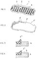
Figur 1- Trägerplatte in einer Ansicht auf die den Reibbelag tragenden Seite
Figur 2- Alternative Ausgestaltung gemäß
Figur 1 Figur 3- Modellträgerplatte in ungepreßtem Zustand
Figur 4- Modellträgerplatte im gepreßten Zustand
- Figure 1
- Carrier plate in a view of the side bearing the friction lining
- Figure 2
- Alternative embodiment according to FIG. 1
- Figure 3
- Model carrier plate in unpressed condition
- Figure 4
- Model carrier plate in the pressed state
Die in der Figur 1 dargestellte Trägerplatte (1) besteht aus einem Graugußwerkstoff der Qualität GGG oder GGL. Die Trägerplatte (1) ist im Sandgußverfahren hergestellt und weist auf der Oberfläche (2) noppenförmige Formkörper (3) auf. Der nicht dargestellte Reibbelag wird auf die Formkörper aufgepreßt und verklammmert sich mit ihnen. Die Formkörper weisen eine Hinterschneidung auf, wodurch die Haftung zwischen Reibbelag und Trägerplatte (1) erhöht wird. Im einfachsten Fall ist die Oberflächenstruktur aus zylinder- (3') im gesamten gestrichelten Bereich (Figur 2) oder würfelförmigen Formkörpern (3) (Figur 1) gebildet. Zur Erzeugung der Hinterschneidung wird das in der Figur 3 und 4 dargestellte Modell (4) der Trägerplatte (1) als Gießformmodell verwendet.The carrier plate (1) shown in FIG. 1 consists of a gray cast iron material of the quality GGG or GGL. The carrier plate (1) is produced using the sand casting process and has knob-shaped molded bodies (3) on the surface (2). The friction lining, not shown, is pressed onto the molded body and clings to it. The moldings have an undercut, which increases the adhesion between the friction lining and the carrier plate (1). In the simplest case, the surface structure is formed from cylindrical (3 ') shaped bodies (FIG. 2) or cube-shaped shaped bodies (3) (FIG. 1). To produce the undercut, the model (4) of the carrier plate (1) shown in FIGS. 3 and 4 is used as a mold model.
Zur Bildung der Formkörper (3, 3') weist das Modell (4) elastomere Formkörper (3'') auf. Beim Abformen wird der Formstoff (loser Sand) auf das Modell (4) aufgebracht und durch hydraulische Pressen (nicht dargestellt) verdichtet. Der Formsand verformt die elastomeren Formkörper (3'') bei der Verdichtung, wie in der Figur 4 dargestellten Weise. Die Schrägstellung der elastomeren Formkörper (3'') erzeugt eine Hinterschneidung (5). Beim Entformen ziehen sich die elastomeren Formkörper (3'') aus der Form und hinterlassen im Sand einen Hohlraum. Dieser Hohlraum wird mit dem beschriebenen flüssigen Metall gefüllt und ergibt so die Trägerplatte (1) mit Hinterschneidungen (5) an den Formkörpern (3, 3') (Figur 1 und 2).To form the shaped bodies (3, 3 '), the model (4) has elastomeric shaped bodies (3''). During molding, the molding material (loose sand) is applied to the model (4) and compressed by hydraulic presses (not shown). The molding sand deforms the elastomeric shaped bodies (3 ″) during compression, as shown in FIG. 4. The inclined position of the elastomeric molded body (3 '') creates an undercut (5). The elastomeric shaped bodies (3 '') pull out during demolding the shape and leave a cavity in the sand. This cavity is filled with the liquid metal described and thus results in the carrier plate (1) with undercuts (5) on the shaped bodies (3, 3 ') (Figures 1 and 2).
Claims (7)
Applications Claiming Priority (2)
| Application Number | Priority Date | Filing Date | Title |
|---|---|---|---|
| DE19532019 | 1995-08-31 | ||
| DE19532019A DE19532019C1 (en) | 1995-08-31 | 1995-08-31 | Carrier plate for friction linings |
Publications (2)
| Publication Number | Publication Date |
|---|---|
| EP0760436A1 true EP0760436A1 (en) | 1997-03-05 |
| EP0760436B1 EP0760436B1 (en) | 2000-03-29 |
Family
ID=7770826
Family Applications (1)
| Application Number | Title | Priority Date | Filing Date |
|---|---|---|---|
| EP96106748A Expired - Lifetime EP0760436B1 (en) | 1995-08-31 | 1996-04-29 | Backing plate for brake lining |
Country Status (2)
| Country | Link |
|---|---|
| EP (1) | EP0760436B1 (en) |
| DE (2) | DE19532019C1 (en) |
Cited By (5)
| Publication number | Priority date | Publication date | Assignee | Title |
|---|---|---|---|---|
| GB2299382B (en) * | 1995-03-24 | 1998-09-16 | T & N Technology Ltd | Backplate for friction material |
| WO1999064762A1 (en) * | 1998-06-10 | 1999-12-16 | Ray Arbesman | Disc brake backing plate and method of manufacturing same |
| EP1106859A1 (en) * | 1999-12-07 | 2001-06-13 | AlliedSignal Bremsbelag GmbH | Brake lining with support plate and method for manufacturing support plates for brake linings |
| DE10347409A1 (en) * | 2003-10-11 | 2005-05-12 | Metek Metallverarbeitungsgmbh | Brake pad carrying device in particular for bicycle, comprising rows of projections for case of emergency |
| US20180363718A1 (en) * | 2016-02-26 | 2018-12-20 | Knorr-Bremse Systeme Fuer Nutzfahrzeuge Gmbh | Brake Lining of a Disk Brake and Brake Pad Set |
Families Citing this family (12)
| Publication number | Priority date | Publication date | Assignee | Title |
|---|---|---|---|---|
| DE19953405A1 (en) * | 1999-11-06 | 2001-05-10 | Cww Gerko Akustik Gmbh & Co Kg | Brake shoe comprises a backing plate and a friction lining which is attached to the backing plated by a layer of peroxidic reticulated silicone adhesive |
| DE10350725B4 (en) * | 2003-10-30 | 2006-10-12 | Tmd Friction Services Gmbh | Pad carrier plate and method for its production |
| DE202006021094U1 (en) | 2006-02-01 | 2012-07-11 | Knorr-Bremse Systeme für Nutzfahrzeuge GmbH | Brake pad for a disc brake |
| DE102006004550B4 (en) | 2006-02-01 | 2016-12-22 | Knorr-Bremse Systeme für Nutzfahrzeuge GmbH | Brake pad for a disc brake |
| DE102007017785B3 (en) * | 2007-04-16 | 2008-11-06 | Federal-Mogul Friction Products Gmbh | Brake pad with a back plate with increased rigidity |
| DE202009017931U1 (en) | 2009-03-03 | 2011-01-20 | Stanz- Und Umformtechnik Jancer Gmbh | Brake pad support retaining plate |
| DE102010031889A1 (en) | 2010-07-21 | 2012-01-26 | Jancer Vermögensverwaltungs Ug (Haftungsbeschränkt) & Co. Kg | Method for producing a brake pad carrier |
| DE102012103196B4 (en) | 2012-03-26 | 2023-08-24 | ABC Advanced Brake Components | Brake pad backing plate and method of manufacturing a brake pad backing plate |
| EP3253986B1 (en) | 2015-02-07 | 2021-05-05 | Gienanth GmbH | Support plate for a brake lining and brake equipped with such a support plate together with friction linings |
| DE102018116304A1 (en) * | 2018-07-05 | 2020-01-09 | Knorr-Bremse Systeme für Nutzfahrzeuge GmbH | Brake pad and process for its manufacture |
| DE102019115587A1 (en) * | 2019-06-07 | 2020-12-10 | Tmd Friction Services Gmbh | Carrier plate with anchoring ribs, method for manufacturing a carrier plate |
| CN114776733B (en) * | 2022-05-11 | 2023-11-24 | 空间液态金属科技发展(江苏)有限公司 | High heat dissipation type disc brake system |
Citations (4)
| Publication number | Priority date | Publication date | Assignee | Title |
|---|---|---|---|---|
| US4569424A (en) * | 1984-01-27 | 1986-02-11 | Taylor Jr James L | Brake shoe construction |
| WO1989009889A1 (en) * | 1988-04-07 | 1989-10-19 | De Forenede Jernstøberier A/S | DISc BRAKE DEVICE FOR AUTOMOBILES, BRAKE DISC AND BRAKE BLOCK THEREFOR AND METHODS OF THE MANUFACTURING THEREOF |
| EP0581988A1 (en) * | 1992-08-05 | 1994-02-09 | AlliedSignal Bremsbelag GmbH | Brake shoe and method of manufacturing same as well as magnet rail brake for road- and rail vehicles, especially for rail vehicles with high and super high speeds |
| DE4332669A1 (en) * | 1993-09-25 | 1995-03-30 | Griwe Innovative Umformtechnik | Brake-pad carrier |
Family Cites Families (5)
| Publication number | Priority date | Publication date | Assignee | Title |
|---|---|---|---|---|
| DE1957751U (en) * | 1967-01-11 | 1967-03-30 | Bergische Stahlindustrie | BRAKE SHOE WITH FRICTION PAD. |
| DE8201404U1 (en) * | 1982-01-22 | 1982-08-05 | Jurid Werke Gmbh, 2056 Glinde | FRICTION COVER, ESPECIALLY FOR DISC AND RAILWAY BRAKE PADS, DRUM BRAKE SHOES, CLUTCH DISKS OD. DGL. |
| DE3420424A1 (en) * | 1984-06-01 | 1985-12-05 | Alfred Teves Gmbh, 6000 Frankfurt | AUTOMATED METHOD FOR PRODUCING BRAKE PADS AND DEVICE FOR IMPLEMENTING THE METHOD |
| DE4138933C2 (en) * | 1991-11-27 | 2002-07-11 | Jurid Werke Gmbh | Method for producing carrier plates for brake linings for rail and rail-bound vehicles and brake lining with a carrier plate produced by the method |
| GB9515926D0 (en) * | 1995-08-03 | 1995-10-04 | T & N Technology Ltd | Manufacture of brake pads |
-
1995
- 1995-08-31 DE DE19532019A patent/DE19532019C1/en not_active Revoked
-
1996
- 1996-04-29 EP EP96106748A patent/EP0760436B1/en not_active Expired - Lifetime
- 1996-04-29 DE DE59604820T patent/DE59604820D1/en not_active Expired - Lifetime
Patent Citations (4)
| Publication number | Priority date | Publication date | Assignee | Title |
|---|---|---|---|---|
| US4569424A (en) * | 1984-01-27 | 1986-02-11 | Taylor Jr James L | Brake shoe construction |
| WO1989009889A1 (en) * | 1988-04-07 | 1989-10-19 | De Forenede Jernstøberier A/S | DISc BRAKE DEVICE FOR AUTOMOBILES, BRAKE DISC AND BRAKE BLOCK THEREFOR AND METHODS OF THE MANUFACTURING THEREOF |
| EP0581988A1 (en) * | 1992-08-05 | 1994-02-09 | AlliedSignal Bremsbelag GmbH | Brake shoe and method of manufacturing same as well as magnet rail brake for road- and rail vehicles, especially for rail vehicles with high and super high speeds |
| DE4332669A1 (en) * | 1993-09-25 | 1995-03-30 | Griwe Innovative Umformtechnik | Brake-pad carrier |
Cited By (7)
| Publication number | Priority date | Publication date | Assignee | Title |
|---|---|---|---|---|
| GB2299382B (en) * | 1995-03-24 | 1998-09-16 | T & N Technology Ltd | Backplate for friction material |
| WO1999064762A1 (en) * | 1998-06-10 | 1999-12-16 | Ray Arbesman | Disc brake backing plate and method of manufacturing same |
| EP1106859A1 (en) * | 1999-12-07 | 2001-06-13 | AlliedSignal Bremsbelag GmbH | Brake lining with support plate and method for manufacturing support plates for brake linings |
| EP1741952A1 (en) * | 1999-12-07 | 2007-01-10 | AlliedSignal Bremsbelag GmbH | Brake pad for rail and not rail-bound vehicles |
| DE10347409A1 (en) * | 2003-10-11 | 2005-05-12 | Metek Metallverarbeitungsgmbh | Brake pad carrying device in particular for bicycle, comprising rows of projections for case of emergency |
| DE10347409B4 (en) * | 2003-10-11 | 2008-01-17 | Metek Metallverarbeitungsgesellschaft Mbh | Brake pad carrier plate of a bicycle disc brake |
| US20180363718A1 (en) * | 2016-02-26 | 2018-12-20 | Knorr-Bremse Systeme Fuer Nutzfahrzeuge Gmbh | Brake Lining of a Disk Brake and Brake Pad Set |
Also Published As
| Publication number | Publication date |
|---|---|
| DE19532019C1 (en) | 1997-02-13 |
| DE59604820D1 (en) | 2000-05-04 |
| EP0760436B1 (en) | 2000-03-29 |
Similar Documents
| Publication | Publication Date | Title |
|---|---|---|
| DE19532019C1 (en) | Carrier plate for friction linings | |
| EP2359021B1 (en) | Brake disc | |
| DE60114275T2 (en) | Method for producing a reinforced thermoplastic workpiece and mold | |
| EP0777830B1 (en) | Disk brake calliper | |
| DE112011101382T5 (en) | A molding method for assembling cast pieces without a model based on an uneven rib structure | |
| DE19834571A1 (en) | Fiber-reinforced composite body, e.g. an internally vented brake disk, is produced from a preform having a metal or silicon core which acts as a metal or silicon source during melt infiltration | |
| DE4127113A1 (en) | Disc brake shoe - has support plate to which lining is sintered | |
| DE4340464A1 (en) | Process for producing a friction ring for clutches or brakes | |
| EP0503625B1 (en) | Friction pad for a disc brake | |
| DE2547499B2 (en) | Method of attaching a pile overlay to a support | |
| EP1599682B1 (en) | Lining support plate and associated production method | |
| EP1256741B1 (en) | Brake or clutch lining and method for its production | |
| DE102008002538A1 (en) | Brake caliper of at least 2 components | |
| DE2165058B2 (en) | Method and apparatus for making a composite casting made of a base metal and a hard surface layer | |
| DE2210950A1 (en) | Manufacturing process for semi-metal coverings see | |
| DE19532085A1 (en) | Dimensionally stable seal prodn., for antifriction bearings | |
| DE102010025327A1 (en) | Method for producing a friction lining | |
| DE202009012778U1 (en) | Composite brake block sole and composite brake block | |
| DE102004023215B4 (en) | Method for producing a brake disk | |
| EP1820620A1 (en) | Method and device for producing friction linings | |
| DE888602C (en) | Process for the production of permanent forms or model facilities | |
| DE2940171C2 (en) | Model for making casting molds | |
| DE19847087C1 (en) | Method for making metal press molds for roof tiles having both durability and excellent release characteristics | |
| DE102006035937A1 (en) | - Shaping tool with a punch as active tool part, a clamp, and a mold where the active tool part can be a shell (sic) useful in vehicle construction is cheaper and quicker to produce than previous tools | |
| DE102019115587A1 (en) | Carrier plate with anchoring ribs, method for manufacturing a carrier plate |
Legal Events
| Date | Code | Title | Description |
|---|---|---|---|
| PUAI | Public reference made under article 153(3) epc to a published international application that has entered the european phase |
Free format text: ORIGINAL CODE: 0009012 |
|
| AK | Designated contracting states |
Kind code of ref document: A1 Designated state(s): DE FR GB |
|
| 17P | Request for examination filed |
Effective date: 19970319 |
|
| 17Q | First examination report despatched |
Effective date: 19990122 |
|
| RAP3 | Party data changed (applicant data changed or rights of an application transferred) |
Owner name: FEDERAL-MOGUL BURSCHEID GMBH |
|
| GRAG | Despatch of communication of intention to grant |
Free format text: ORIGINAL CODE: EPIDOS AGRA |
|
| GRAG | Despatch of communication of intention to grant |
Free format text: ORIGINAL CODE: EPIDOS AGRA |
|
| GRAH | Despatch of communication of intention to grant a patent |
Free format text: ORIGINAL CODE: EPIDOS IGRA |
|
| GRAH | Despatch of communication of intention to grant a patent |
Free format text: ORIGINAL CODE: EPIDOS IGRA |
|
| GRAA | (expected) grant |
Free format text: ORIGINAL CODE: 0009210 |
|
| AK | Designated contracting states |
Kind code of ref document: B1 Designated state(s): DE FR GB |
|
| REF | Corresponds to: |
Ref document number: 59604820 Country of ref document: DE Date of ref document: 20000504 |
|
| ET | Fr: translation filed | ||
| RAP2 | Party data changed (patent owner data changed or rights of a patent transferred) |
Owner name: FEDERAL-MOGUL FRICTION PRODUCTS GMBH |
|
| GBT | Gb: translation of ep patent filed (gb section 77(6)(a)/1977) |
Effective date: 20000602 |
|
| PLBE | No opposition filed within time limit |
Free format text: ORIGINAL CODE: 0009261 |
|
| STAA | Information on the status of an ep patent application or granted ep patent |
Free format text: STATUS: NO OPPOSITION FILED WITHIN TIME LIMIT |
|
| 26N | No opposition filed | ||
| REG | Reference to a national code |
Ref country code: GB Ref legal event code: IF02 |
|
| REG | Reference to a national code |
Ref country code: FR Ref legal event code: PLFP Year of fee payment: 20 |
|
| PGFP | Annual fee paid to national office [announced via postgrant information from national office to epo] |
Ref country code: GB Payment date: 20150325 Year of fee payment: 20 |
|
| PGFP | Annual fee paid to national office [announced via postgrant information from national office to epo] |
Ref country code: DE Payment date: 20150429 Year of fee payment: 20 |
|
| PGFP | Annual fee paid to national office [announced via postgrant information from national office to epo] |
Ref country code: FR Payment date: 20150325 Year of fee payment: 20 |
|
| REG | Reference to a national code |
Ref country code: DE Ref legal event code: R071 Ref document number: 59604820 Country of ref document: DE |
|
| REG | Reference to a national code |
Ref country code: GB Ref legal event code: PE20 Expiry date: 20160428 |
|
| PG25 | Lapsed in a contracting state [announced via postgrant information from national office to epo] |
Ref country code: GB Free format text: LAPSE BECAUSE OF EXPIRATION OF PROTECTION Effective date: 20160428 |