EP0757213A2 - Closing device for a ventilation unit - Google Patents
Closing device for a ventilation unit Download PDFInfo
- Publication number
- EP0757213A2 EP0757213A2 EP96109913A EP96109913A EP0757213A2 EP 0757213 A2 EP0757213 A2 EP 0757213A2 EP 96109913 A EP96109913 A EP 96109913A EP 96109913 A EP96109913 A EP 96109913A EP 0757213 A2 EP0757213 A2 EP 0757213A2
- Authority
- EP
- European Patent Office
- Prior art keywords
- slats
- closure device
- slide
- recesses
- closed position
- Prior art date
- Legal status (The legal status is an assumption and is not a legal conclusion. Google has not performed a legal analysis and makes no representation as to the accuracy of the status listed.)
- Granted
Links
Images

Classifications
-
- F—MECHANICAL ENGINEERING; LIGHTING; HEATING; WEAPONS; BLASTING
- F24—HEATING; RANGES; VENTILATING
- F24F—AIR-CONDITIONING; AIR-HUMIDIFICATION; VENTILATION; USE OF AIR CURRENTS FOR SCREENING
- F24F13/00—Details common to, or for air-conditioning, air-humidification, ventilation or use of air currents for screening
- F24F13/02—Ducting arrangements
- F24F13/06—Outlets for directing or distributing air into rooms or spaces, e.g. ceiling air diffuser
- F24F13/075—Outlets for directing or distributing air into rooms or spaces, e.g. ceiling air diffuser having parallel rods or lamellae directing the outflow, e.g. the rods or lamellae being individually adjustable
-
- F—MECHANICAL ENGINEERING; LIGHTING; HEATING; WEAPONS; BLASTING
- F24—HEATING; RANGES; VENTILATING
- F24F—AIR-CONDITIONING; AIR-HUMIDIFICATION; VENTILATION; USE OF AIR CURRENTS FOR SCREENING
- F24F13/00—Details common to, or for air-conditioning, air-humidification, ventilation or use of air currents for screening
- F24F13/08—Air-flow control members, e.g. louvres, grilles, flaps or guide plates
- F24F13/10—Air-flow control members, e.g. louvres, grilles, flaps or guide plates movable, e.g. dampers
- F24F13/14—Air-flow control members, e.g. louvres, grilles, flaps or guide plates movable, e.g. dampers built up of tilting members, e.g. louvre
- F24F13/1426—Air-flow control members, e.g. louvres, grilles, flaps or guide plates movable, e.g. dampers built up of tilting members, e.g. louvre characterised by actuating means
- F24F2013/1473—Air-flow control members, e.g. louvres, grilles, flaps or guide plates movable, e.g. dampers built up of tilting members, e.g. louvre characterised by actuating means with cams or levers
Definitions
- the invention relates to a closure device for a ventilation device, in particular for a fan, according to the preamble of claim 1.
- Closure devices of this type are known in particular for fans. Lamellae lying parallel to one another are arranged pivotably about their longitudinal axis in a plane in front of the air inlet opening (or an air outlet opening) of the fan. When closed, the slats form a flat surface that closes the air outlet opening. When the fan is switched on, an actuating device is usually automatically activated, which swivels the slats into an open position, so that the air outlet opening is opened and an air flow can escape between the slats.
- an actuating device is usually automatically activated, which swivels the slats into an open position, so that the air outlet opening is opened and an air flow can escape between the slats.
- the area formed by the lamellae in the closed state does not always correspond to the visual ideas.
- the invention is therefore based on the object of providing a closure device, in particular for a fan, which, when closed, has a special appearance, but without the functionality suffers especially in the open state.
- the actuating device with different driving play ensures that the slats are brought into an open position in which they have the same opening angle to a common reference plane, although the closing angles of the slats in the closed state are different with respect to the said reference plane.
- an optimal air inlet or air outlet can be achieved.
- the opening or closing angle relates to an angle which lies between the reference plane and a plane which is different from the Swivel axis and a longitudinal edge of the slat is defined.
- the actuating device is preferably designed as a slide which, in a further development of the invention, has recesses into which, for example, driving pins of the slats engage.
- the driving pins are taken along, whereby the slats are pivoted about their longitudinal axis.
- the recesses at one end of the slide are minimal, preferably as a bore, and at the other end at the maximum, for example as an elongated hole, the slats are carried at different times when the slide is actuated and are therefore pivoted through different angles.
- the cutouts are preferably dimensioned such that the slats from different angular positions in the closed state are first all brought into the same angular position with respect to a reference plane and then synchronously into the end position.
- the driving pins engage in part-circular recesses which, on the one hand, serve as guides for the pivoting movement and, on the other hand, form stops in order to prevent pivoting about the desired end positions.
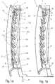
- a closure device 1 shown in Figure 1 comprises a frame 3 and a plurality of slats 5 mounted in the frame.
- Each of the slats 5 has bearing pins 7 on both longitudinal ends, which engage in recesses provided in the frame. This type of attachment allows the individual slats 5 to pivot about the common longitudinal axis of the journal 7.
- 5 levers 9 are attached to the rear side of the fins facing the fan side I, which have lever pins 11 at their end remote from the fins. These lever pins run transversely to the lever 9 and essentially parallel to the adjacent bearing pin 7.
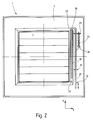
- a slide 15 which extends transversely to the longitudinal direction of the slats.
- recesses 17 are provided in the slide 15, which are of different sizes.
- the recess 17. 1 on a slide end 19 is merely designed as a bore, the diameter of which essentially corresponds to that of the lever pin 11.
- the recess 17.7 is designed as an elongated hole.
- the recesses 17.2 to 17.6 in between are also designed as elongated holes, the longitudinal dimension increasing from recess to recess.
- FIG. 1 shows part-circular regions 22, which are also shown in broken lines. These are recesses in the frame 3, in which the lever pins 11 of the slats 5 engage and are guided when pivoting. For this purpose, these recesses extend on an arc around the pivot axis of the slats. The two Longitudinal ends of the recesses also serve as stops and thus define the two end positions of the slats and also offer lateral guidance.
- the slide 15 is U-shaped, one leg 23 being guided in a groove 25 of the frame 3.
- the other leg 27 of the slider 15 is also guided by two extensions 29, 31 attached to the frame.
- the extension 29 also serves as an abutment for a return device, preferably a return spring 33, which is attached to a bracket 35 attached to the leg 27.
- the reset device 33 is dimensioned so that it supports the closing operation.
- webs 36 extending transversely to the longitudinal direction of the leg 23 are formed on one of the side walls forming the groove 25.
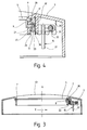
- FIGS. 3 and 4 show the cross-section of the closure device to illustrate the structure.
- the lamella 5 is pivotally mounted in corresponding recesses of the housing 3 by means of the bearing pin 7.
- the lever 9 is attached, which extends perpendicular to the slat.
- the lever pin 11 is attached, which passes through the recess 22 serving as a guide in the housing 3 and ends in the recess 17 in a leg 23 of the slide 15.
- the slide 15, that is to say the leg 23, is guided in the groove 25, which is formed by two wall parts 37, 39 of the housing 3.
- the leg 23 extending in the groove preferably has a plurality of bead-like projections 41 which are directed towards the wall part 39. This can avoid that the entire side surface of the leg 23 rests on the wall part 39.
- a further improvement is provided by the webs 36 already mentioned, which are provided on the wall part 37.
- Figure 3 also clearly shows that the shape of the frame 3 has a curvature 43 to the outside.
- the curvature 43 extends — referring to FIG. 2- in the x direction.
- a curvature in the y direction corresponding to the curvature of the lamellae can, however, be additionally or alternatively provided. In the exemplary embodiment shown, the curvature of the lamellae only runs in the y direction.
- the closed position is shown in FIG.
- the slats 5 form a closed curved surface, with adjacent slats overlapping. Due to the curvature, the top lamella 5.1 in the figure has an angle ⁇ with respect to the vertical, while the bottom lamella 5.7 forms an entirely different angle ⁇ with the vertical.
- the angles of the other slats 5.2 to 5.6 lie within the range spanned by the two angles ⁇ and ⁇ .
- the slats 5 should all include the same angle to the vertical in the open state, the uppermost slat 5.1 must therefore be pivoted through a larger angle of rotation than the lowest slat 5.7.
- the recesses 17, in which the lever pins 11 engage are dimensioned differently.
- the recess 11 is formed as a bore so that the bearing pin 11 engages without play. This ensures a direct conversion of a slide movement of the slide 15 into a tilting movement of this lamella.
- the recess 17 is designed as an elongated hole.
- the slat 5.7 only executes a tilting movement after a certain slide travel. This means that when the lever is moved in the direction of the arrow 46, the slat 5.1 is actuated first, then the adjacent slat 5.2 and so on, and finally the slat 5.7.
- Both the opening position of the slats and the aforementioned end position are defined by the recesses 22, which in addition to their guiding function also serve as stops.
- the slats 5 are closed in the reverse manner, the slat 5.1 being moved first and the lowest slat 5.7 only at the end.
- the slide 15 can be actuated automatically or manually.
Landscapes
- Engineering & Computer Science (AREA)
- Chemical & Material Sciences (AREA)
- Combustion & Propulsion (AREA)
- Mechanical Engineering (AREA)
- General Engineering & Computer Science (AREA)
- Specific Sealing Or Ventilating Devices For Doors And Windows (AREA)
- Air-Flow Control Members (AREA)
- Blinds (AREA)
- Cooling Or The Like Of Electrical Apparatus (AREA)
Abstract
Description
Die Erfindung betrifft eine Verschlußvorrichtung für eine lufttechnische Einrichtung, insbesondere für einen Ventilator, gemäß Oberbegriff des Anspruchs 1.The invention relates to a closure device for a ventilation device, in particular for a fan, according to the preamble of
Derartige Verschlußvorrichtungen sind insbesondere für Ventilatoren bekannt. Parallel zueinander liegende Lamellen sind dabei um ihre Längsachse schwenkbar in einer Ebene vor der Lufteintrittsöffnung (oder einer Luftaustrittsöffnung) des Ventilators angeordnet. In geschlossenem Zustand bilden die Lamellen eine ebene Fläche, die die Luftaustrittsöffnung verschließt. Beim Einschalten des Ventilators wird eine Betätigungsvorrichtung zumeist automatisch aktiviert, die die Lamellen in eine Öffnungsstellung schwenkt, so daß die Luftaustrittsöffnung freigegeben wird und eine Luftströmung zwischen den Lamellen austreten kann. Die im geschlossenen Zustand von den Lamellen gebildete Fläche entspricht jedoch nicht immer den optischen Vorstellungen.Closure devices of this type are known in particular for fans. Lamellae lying parallel to one another are arranged pivotably about their longitudinal axis in a plane in front of the air inlet opening (or an air outlet opening) of the fan. When closed, the slats form a flat surface that closes the air outlet opening. When the fan is switched on, an actuating device is usually automatically activated, which swivels the slats into an open position, so that the air outlet opening is opened and an air flow can escape between the slats. However, the area formed by the lamellae in the closed state does not always correspond to the visual ideas.
Der Erfindung liegt deshalb die Aufgabe zugrunde, eine Verschlußvorrichtung insbesondere für einen Ventilator vorzusehen, die -in geschlossenem Zustand- ein besonderes Aussehen hat, ohne daß jedoch die Funktionalität insbesondere im geöffneten Zustand darunter leidet.The invention is therefore based on the object of providing a closure device, in particular for a fan, which, when closed, has a special appearance, but without the functionality suffers especially in the open state.
Diese Aufgabe wird durch die Merkmale des Anspruchs 1 gelöst. Dadurch, daß die Lamellen so angeordnet sind, daß sie in geschlossenem Zustand eine quer zu den Langsachsen gewölbte, vorzugsweise konvex nach außen gewölbte Fläche bilden, wird eine besondere optische Wirkung erzielt. Unter "gewölbter Fläche" ist dabei auch eine Fläche zu verstehen, die sich aus mehreren ebenen Flächen zusammensetzt, wobei die die ebenen Flächen einhüllende Fläche dann gewölbt ist. Beispielsweise bei der vorteilhaften Verwendung von in sich ebenen Lamellen setzt sich die von den Lamellen gebildete Fläche aus mehreren (abhängig von der Lamellenanzahl) ebenen Flächenabschnitten zusammen.This object is solved by the features of
Darüber hinaus sorgt die Betätigungsvorrichtung mit unterschiedlichem Mitnahmespiel dafür, daß die Lamellen in eine Öffnungsstellung gebracht werden, in der sie den gleichen Öffnungswinkel zu einer gemeinsamen Bezugsebene aufweisen, obgleich die Schließwinkel der Lamellen in geschlossenem Zustand bezüglich der genannten Bezugsebene unterschiedlich sind. Trotz der gewölbten Anordnung der Lamellen kann folglich ein optimaler Lufteintritt oder Luftaustritt erreicht werden. Bei in sich gewölbten Lamellen bezieht sich der Öffnungs- beziehungsweise Schließwinkel auf einen Winkel, der zwischen der Bezugsebene und einer Ebene liegt, die von der Schwenkachse und einer Längskante der Lamelle definiert wird.In addition, the actuating device with different driving play ensures that the slats are brought into an open position in which they have the same opening angle to a common reference plane, although the closing angles of the slats in the closed state are different with respect to the said reference plane. In spite of the curved arrangement of the slats, an optimal air inlet or air outlet can be achieved. In the case of domed lamellae, the opening or closing angle relates to an angle which lies between the reference plane and a plane which is different from the Swivel axis and a longitudinal edge of the slat is defined.
Vorzugsweise ist die Betätigungsvorrichtung als Schieber ausgebildet, der in einer Weiterbildung der Erfindung Ausnehmungen aufweist, in die beispielsweise Mitnahmezapfen der Lamellen eingreifen. Durch Verschieben des vorzugsweise in einer Nut des Rahmens geführten Schiebers werden die Mitnahmezapfen mitgenommen, wodurch die Lamellen um ihre Längsachse verschwenkt werden. Dadurch, daß die Aussparungen an einem Ende des Schiebers minimal, vorzugsweise als eine Bohrung, und am anderen Ende maximal, beispielsweise als Langloch, ausgebildet sind, werden die Lamellen beim Betätigen des Schiebers zu unterschiedlichen Zeitpunkten mitgenommen und mithin um unterschiedliche Winkel verschwenkt.The actuating device is preferably designed as a slide which, in a further development of the invention, has recesses into which, for example, driving pins of the slats engage. By moving the slide, which is preferably guided in a groove of the frame, the driving pins are taken along, whereby the slats are pivoted about their longitudinal axis. Characterized in that the recesses at one end of the slide are minimal, preferably as a bore, and at the other end at the maximum, for example as an elongated hole, the slats are carried at different times when the slide is actuated and are therefore pivoted through different angles.
Vorzugsweise sind die Aussparungen so dimensioniert, daß die Lamellen aus unterschiedlichen Winkelstellungen in geschlossenem Zustand zunächst alle in eine gleiche Winkelstellung gegenüber einer Bezugsebene gebracht werden und anschließend synchron in die Endstellung.The cutouts are preferably dimensioned such that the slats from different angular positions in the closed state are first all brought into the same angular position with respect to a reference plane and then synchronously into the end position.
In einer Weiterbildung der Erfindung greifen die Mitnahmezapfen in teilkreisförmige Ausnehmungen ein, die einerseits den Lamellen als Führung für die Schwenkbewegung dienen und andererseits Anschläge bilden, um ein Verschwenken über die gewünschten Endstellungen zu verhindern.In a further development of the invention, the driving pins engage in part-circular recesses which, on the one hand, serve as guides for the pivoting movement and, on the other hand, form stops in order to prevent pivoting about the desired end positions.
Weitere vorteilhafte Ausgestaltungen sind den übrigen Unteransprüchen zu entnehmen.Further advantageous embodiments can be found in the remaining subclaims.
Die Erfindung wird nun anhand eines Ausführungsbeispiels mit Bezug auf die Zeichnungen näher beschrieben. Dabei zeigen:
- Figur 1a bis 1c
- einen schematischen Querschnitt der Verschlußvorrichtung bei unterschiedlichen Lamellenstellungen;
- Figur 2
- schematisch die Unterseite der Vorrichtung;
Figur 3- eine Schnittansicht der in Figur 2 gegezeigten Verschlußvorrichtung; und
- Figur 4
- eine vergrößerte Ausschnittsdarstellung eines in
Figur 3 gezeigten Bereichs.
- Figure 1a to 1c
- a schematic cross section of the closure device with different slat positions;
- Figure 2
- schematically the bottom of the device;
- Figure 3
- a sectional view of the closure device shown in Figure 2; and
- Figure 4
- an enlarged detail of an area shown in Figure 3.
Eine in Figur 1 gezeigte Verschlußvorrichtung 1 umfaßt einen Rahmen 3 sowie mehrere im Rahmen gelagerte Lamellen 5. Jede der Lamellen 5 weist an beiden Längsenden Lagerzapfen 7 auf, die in entsprechend im Rahmen vorgesehene Aussparungen eingreifen. Diese Art der Befestigung läßt ein Verschwenken der einzelnen Lamellen 5 um die gemeinsame Längsachse der Lagerzapfen 7 zu. Desweiteren sind an der zur Ventilatorseite I gerichteten Rückseite der Lamellen 5 Hebel 9 angebracht, die an ihrem der Lamelle abliegenden Ende Hebelzapfen 11 aufweisen. Diese Hebelzapfen verlaufen quer zu dem Hebel 9 und im wesentlichen parallel zu dem benachbarten Lagerzapfen 7.A
Aus Figur 1 ist weiter ersichtlich, daß die Lamellen 5 -im geschlossenen Zustand- eine nach außen A gewölbte Fläche bilden. Um eine optimale Abdichtung nach innen I zum Ventilator hin zu erreichen, überlappen sich benachbarte Lamellen, wobei die jeweiligen Überlappungsbereiche der einzelnen Lamellen 5 jeweils nur halbe Materialdicke aufweisen. Damit läßt sich eine schuppenförmige Anordnung vermeiden und nach außen hin eine optisch ansprechende glatte Fläche erzielen.From Figure 1 it can also be seen that the slats 5 - in the closed state - form an outwardly curved surface A. In order to achieve an optimal seal towards the inside I towards the fan, adjacent lamellae overlap, the respective overlapping areas of the
Zum Verschwenken der einzelnen Lamellen 5 ist ein Schieber 15 vorgesehen, der sich quer zur Längsrichtung der Lamellen erstreckt. Zur Aufnahme der Hebelzapfen 11 sind im Schieber 15 Aussparungen 17 vorgesehen, die unterschiedlich groß ausgebildet sind. So ist die Aussparung 17.1 am einen Schieberende 19 lediglich als Bohrung ausgebildet, deren Durchmesser im wesentlichen dem des Hebelzapfens 11 entspricht. Am anderen Ende 21 des Schiebers 15 ist die Aussparung 17.7 als Langloch ausgeführt. Die dazwischen liegenden Aussparungen 17.2 bis 17.6 sind ebenfalls als Langlöcher ausgebildet, wobei die Längsabmessung jeweils von Aussparung zu Aussparung zunimmt.To pivot the
Die Figur 1 läßt noch gestrichelt dargestellte teilkreisförmige Bereiche 22 erkennen. Dabei handelt es sich um Ausnehmungen im Rahmen 3, in die die Hebelzapfen 11 der Lamellen 5 eingreifen und beim Verschwenken geführt sind. Zu diesem Zweck erstrecken sich diese Ausnehmungen auf einem Kreisbogen um die Schwenkachse der Lamellen. Die beiden Längsenden der Ausnehmungen dienen zusätzlich als Anschläge und definieren somit die beiden Endstellungen der Lamellen und bieten auch seitliche Führung.FIG. 1 shows part-
Aus der in Figur 2 gezeigten Draufsicht der Unterseite der Verschlußvorrichtung 1 ist ersichtlich, daß der Schieber 15 U-förmig ausgebildet ist, wobei ein Schenkel 23 in einer Nut 25 des Rahmens 3 geführt ist. Der andere Schenkel 27 des Schiebers 15 wird ebenfalls durch zwei am Rahmen angebrachte Fortsätze 29, 31 geführt.From the plan view of the underside of the
Der Fortsatz 29 dient darüber hinaus als Widerlager für eine Rückstellvorrichtung, vorzugsweise eine Rückstellfeder 33, die an einem am Schenkel 27 angebrachten Ausleger 35 befestigt ist. Die Rückstellvorrichtung 33 ist dabei so dimensioniert, daß sie die Schließbetätigung unterstützt.The
Zur Führung des Schenkels 23 in der Nut 25 sind quer zur Längsrichtung des Schenkels 23 sich erstreckende Stege 36 an einer der die Nut 25 bildenden Seitenwand ausgebildet.To guide the
In den Figuren 3 und 4 ist zur Verdeutlichung des Aufbaus der Verschlußvorrichtung diese im Querschnitt gezeigt. In Figur 3 ist deutlich zu erkennen, daß die Lamelle 5 mit Hilfe der Lagerzapfen 7 in entsprechenden Ausnehmungen des Gehäuses 3 schwenkbar gelagert ist. An einem seitlichen Ende der Lamelle 5 ist der Hebel 9 angebracht, der sich senkrecht zur Lamelle erstreckt. Am Hebelende ist der Hebelzapfen 11 angebracht, der die als Führung dienende Ausnehmung 22 im Gehäuse 3 durchgreift und in der Aussparung 17 in einem Schenkel 23 des Schiebers 15 endet.FIGS. 3 and 4 show the cross-section of the closure device to illustrate the structure. In Figure 3 it can be clearly seen that the
Die Führung des Schiebers 15, das heißt des Schenkels 23 erfolgt in der Nut 25, die durch zwei Wandteile 37, 39 des Gehäuses 3 gebildet wird.The
Zur Verbesserung der Führung weist der sich in der Nut erstreckende Schenkel 23 vorzugsweise mehrere wulstartige Vorsprünge 41 auf, die zu dem Wandteil 39 gerichtet sind. Damit läßt sich vermeiden, daß die gesamte Seitenfläche des Schenkels 23 am Wandteil 39 anliegt. Eine weitere Verbesserung liefern die -bereits erwähnten- Stege 36, die am Wandteil 37 vorgesehen sind.To improve the guidance, the
Figur 3 läßt darüber hinaus deutlich erkennen, daß auch die Form des Rahmens 3 nach außen hin eine Wölbung 43 aufweist. Die Wölbung 43 verläuft dabei -bezugnehmend auf Figur 2- in x-Richtung. Eine der Wölbung der Lamellen entsprechende Wölbung in y-Richtung kann jedoch zusätzlich oder alternativ vorgesehen sein. Die Wölbung der Lamellen verläuft im gezeigten Ausführungsbeispiel jedoch nur in y-Richtung.Figure 3 also clearly shows that the shape of the
Im folgenden soll nun anhand der bereits beschriebenen Figuren 1 a bis 1 c die Funktionsweise der Verschlußvorrichtung anhand von drei Verschlußstellungen erläutert werden.In the following, the functioning of the closure device will now be explained with reference to the already described FIGS. 1 a to 1 c using three closure positions.
In Figur 1 a ist die Schließstellung gezeigt. Die Lamellen 5 bilden dabei -wie bereits erwähnt- eine geschlossene gewölbte Fläche, wobei sich benachbarte Lamellen überlappen. Bedingt durch die Wölbung nimmt die -in der Figur- oberste Lamelle 5.1 gegenüber der Vertikalen einen Winkel α ein, während die unterste Lamelle 5.7 einen gänzlich anderen Winkel β mit der Vertikalen einschließt. Die Winkel der übrigen Lamellen 5.2 bis 5.6 liegen innerhalb des von den beiden Winkeln α und β aufgespannten Bereichs.The closed position is shown in FIG. As already mentioned, the
Um die Lamellen 5 nun in ihre öffnungsstellung zu bringen, ist ein Verschwenken um die Längsachsen der Lagerzapfen 7 gegen den Uhrzeigersinn notwendig, wie dies durch einen Pfeil 45 angedeutet ist.In order to bring the
Da die Lamellen 5 in geöffnetem Zustand alle den gleichen Winkel zur Vertikalen einschließen sollen, muß demnach die oberste Lamelle 5.1 um einen größeren Drehwinkel geschwenkt werden als die unterste Lamelle 5.7. Dafür sind die Aussparungen 17, in die die Hebelzapfen 11 eingreifen, unterschiedlich dimensioniert.Since the
Bei der Lamelle 5.1 ist die Aussparung 11 als Bohrung ausgebildet, so daß der Lagerzapfen 11 spielfrei eingreift. Damit ist eine direkte Umsetzung einer Schieberbewegung des Schiebers 15 in eine Kippbewegung dieser Lamelle gewährleistet.In the slat 5.1, the
Bei der untersten Lamelle 5.7 ist die Aussparung 17 jedoch als Langloch ausgebildet. Im in Figur 1 a gezeichneten Fall führt die Lamelle 5.7 also erst nach einem bestimmten Schieberweg eine Kippbewegung aus. Das bedeutet, daß beim Verschieben des Hebels in Richtung des Pfeils 46 zunächst die Lamelle 5.1 betätigt wird, danach die benachbarte Lamelle 5.2 und so weiter, und letztendlich die Lamelle 5.7.In the lowest slat 5.7, however, the
Die Dimensionierung dieser Aussparungen 17 erfolgt derart, daß zunächst alle Lamellen in eine gleiche Winkelstellung gebracht werden, die -wie in Figur 1 b gezeigt- derjenigen der untersten Lamelle 5.7 entspricht.The dimensioning of these
Aus dieser Lage heraus, beziehungsweise ab diesem Zeitpunkt werden alle Lamellen im wesentlichen synchron in die Endstellung gekippt, die in Figur 1 c dargestellt ist. In dieser Endstellung entspricht die Winkelstellung α der Lamelle 5.1 derjenigen der Lamelle 5.7.From this position, or from this point in time, all the slats are tilted substantially synchronously into the end position, which is shown in FIG. 1 c. In this end position, the angular position α of the slat 5.1 corresponds to that of the slat 5.7.
Sowohl die Öffnungsstellung der Lamellen als auch die zuvor genannte Endstellung werden durch die Ausnehmungen 22 definiert, die neben ihrer Führungsfunktion auch als Anschläge dienen.Both the opening position of the slats and the aforementioned end position are defined by the
Das Schließen der Lamellen 5 erfolgt in umgekehrter Weise, wobei zunächst die Lamelle 5.1 bewegt wird und erst am Ende die unterste Lamelle 5.7.The
Die Betätigung des Schiebers 15 kann dabei automatisch oder aber manuell erfolgen.The
Claims (12)
Applications Claiming Priority (2)
| Application Number | Priority Date | Filing Date | Title |
|---|---|---|---|
| DE19528302A DE19528302C2 (en) | 1995-08-02 | 1995-08-02 | Closure device for an air technology device |
| DE19528302 | 1995-08-02 |
Publications (3)
| Publication Number | Publication Date |
|---|---|
| EP0757213A2 true EP0757213A2 (en) | 1997-02-05 |
| EP0757213A3 EP0757213A3 (en) | 2000-11-15 |
| EP0757213B1 EP0757213B1 (en) | 2003-05-14 |
Family
ID=7768456
Family Applications (1)
| Application Number | Title | Priority Date | Filing Date |
|---|---|---|---|
| EP96109913A Expired - Lifetime EP0757213B1 (en) | 1995-08-02 | 1996-06-20 | Closing device for a ventilation unit |
Country Status (3)
| Country | Link |
|---|---|
| EP (1) | EP0757213B1 (en) |
| AT (1) | ATE240495T1 (en) |
| DE (2) | DE19528302C2 (en) |
Cited By (1)
| Publication number | Priority date | Publication date | Assignee | Title |
|---|---|---|---|---|
| WO1999064793A1 (en) * | 1998-06-10 | 1999-12-16 | ABB Fläkt Oy | Air outlet grille |
Families Citing this family (9)
| Publication number | Priority date | Publication date | Assignee | Title |
|---|---|---|---|---|
| DE19742730B4 (en) * | 1996-09-27 | 2006-03-02 | Valeo Thermique Moteur | Device for regulating an air flow, in particular for a heat exchanger of a motor vehicle |
| DE19826325C2 (en) * | 1998-06-12 | 2001-03-08 | Schako Metallwarenfabrik | Grille for an air outlet |
| DE20100740U1 (en) | 2001-01-16 | 2001-05-31 | TRW Automotive Electronics & Components GmbH & Co.KG, 67677 Enkenbach-Alsenborn | Air vents, in particular for vehicle air conditioning |
| DE102008061054A1 (en) * | 2008-12-08 | 2010-06-17 | Röchling Automotive AG & Co. KG | Ventilation flap drive for motor vehicle, has transmission with cam track and cam as transmission components, where former transmission component is driven to shifting movement |
| DE102009038428B4 (en) * | 2009-08-21 | 2013-04-25 | Audi Ag | Device for opening and closing a spoiler device for a motor vehicle |
| DE202019104394U1 (en) | 2019-08-09 | 2019-08-16 | Illinois Tool Works Inc. | Coupling rod for manipulating in an air vent for vehicles used for use louvers, air vents for a vehicle and Luftausströmersystem |
| RU195258U1 (en) * | 2019-10-25 | 2020-01-21 | Акционерное общество "Тион Умный микроклимат" | Ventilation duct grille |
| DE102021204015A1 (en) | 2021-04-22 | 2022-10-27 | Maico Elektroapparate-Fabrik Gesellschaft mit beschränkter Haftung | Control valve, in particular for a ventilation device, method for operating a control valve and ventilation device with a control valve |
| DE102021213286A1 (en) | 2021-11-25 | 2023-05-25 | Maico Elektroapparate-Fabrik Gesellschaft mit beschränkter Haftung | Control valve, in particular for a ventilation device, method for operating a control valve and ventilation device with a control valve |
Citations (4)
| Publication number | Priority date | Publication date | Assignee | Title |
|---|---|---|---|---|
| US2293065A (en) * | 1939-06-26 | 1942-08-18 | Maurice D Kiczales | Air flow control damper |
| US4653384A (en) * | 1985-12-31 | 1987-03-31 | Kabushiki Kaisha Toshiba | Air supply adjusting mechanism for air conditioner |
| DE3909297A1 (en) * | 1989-03-21 | 1990-09-27 | Eternit Ag | Ventilating arrangement for installation in a row of lights vaulted in the shape of a barrel |
| EP0463697A1 (en) * | 1990-06-22 | 1992-01-02 | Hubertus Gerardus Jacobus Peeters | Ventilating hatch |
Family Cites Families (2)
| Publication number | Priority date | Publication date | Assignee | Title |
|---|---|---|---|---|
| DE7202132U (en) * | 1972-04-06 | Gebr Trox Gmbh | Device for adjusting flowing media, especially air in ventilation or air conditioning systems | |
| FR470588A (en) * | 1914-04-07 | 1914-09-17 | Seraphin Guzzi | Mechanism for aviator |
-
1995
- 1995-08-02 DE DE19528302A patent/DE19528302C2/en not_active Expired - Fee Related
-
1996
- 1996-06-20 AT AT96109913T patent/ATE240495T1/en not_active IP Right Cessation
- 1996-06-20 EP EP96109913A patent/EP0757213B1/en not_active Expired - Lifetime
- 1996-06-20 DE DE59610435T patent/DE59610435D1/en not_active Expired - Fee Related
Patent Citations (4)
| Publication number | Priority date | Publication date | Assignee | Title |
|---|---|---|---|---|
| US2293065A (en) * | 1939-06-26 | 1942-08-18 | Maurice D Kiczales | Air flow control damper |
| US4653384A (en) * | 1985-12-31 | 1987-03-31 | Kabushiki Kaisha Toshiba | Air supply adjusting mechanism for air conditioner |
| DE3909297A1 (en) * | 1989-03-21 | 1990-09-27 | Eternit Ag | Ventilating arrangement for installation in a row of lights vaulted in the shape of a barrel |
| EP0463697A1 (en) * | 1990-06-22 | 1992-01-02 | Hubertus Gerardus Jacobus Peeters | Ventilating hatch |
Cited By (1)
| Publication number | Priority date | Publication date | Assignee | Title |
|---|---|---|---|---|
| WO1999064793A1 (en) * | 1998-06-10 | 1999-12-16 | ABB Fläkt Oy | Air outlet grille |
Also Published As
| Publication number | Publication date |
|---|---|
| EP0757213B1 (en) | 2003-05-14 |
| DE19528302C2 (en) | 2000-08-24 |
| DE19528302A1 (en) | 1997-02-06 |
| ATE240495T1 (en) | 2003-05-15 |
| DE59610435D1 (en) | 2003-06-18 |
| EP0757213A3 (en) | 2000-11-15 |
Similar Documents
| Publication | Publication Date | Title |
|---|---|---|
| DE69731668T2 (en) | OPERATING BAR FOR COVERINGS OF BUILDING OPENINGS | |
| DE2722385C2 (en) | ||
| DE602005004313T2 (en) | Chassis door with controlled movement when opening and closing | |
| DE2730393A1 (en) | AUTOMATIC PLINTH | |
| DE3118823C2 (en) | Ventilation device | |
| DE69829979T3 (en) | METHOD FOR OPENING AND CLOSING AN OPENING ROOF CONSTRUCTION FOR A VEHICLE WITH A FIXED ROOF OPENING, AND SUCH OPENABLE ROOFING | |
| EP1331116B1 (en) | Air nozzle | |
| DE102017206449B4 (en) | Caravan window and opening mechanism therefor | |
| EP0757213A2 (en) | Closing device for a ventilation unit | |
| DE68901930T2 (en) | FAN. | |
| EP1127992B1 (en) | Slat roof | |
| DE19826420A1 (en) | Locking device for windows, doors or similar openings | |
| DE4020334C2 (en) | Wall or roof element with a frame-like support frame and swiveling, plate-like slats | |
| DE3017483C2 (en) | Locking device for preventing the extension arm of a deployment device from hanging out | |
| DE4115220C2 (en) | ||
| EP1310395A2 (en) | Slide system for closing and opening a roof opening | |
| DE102009031686A1 (en) | Vehicle drawer closing mechanism, has actuating device formed from strand, which is connected at end with strap, so that tension at handle causes swiveling of handle and tension at strand and retraction in piston are caused over strap | |
| DE1708407C3 (en) | Locking device for a concealed hinge joint | |
| DE69900423T2 (en) | Pre-assembled and preset sectional door, and its conditioning | |
| DE602004007009T2 (en) | IMPROVED KIPPFENSTER WITH LOCKING | |
| DE19857153C1 (en) | Air nozzle for motor vehicle has discharge opening with coupled vanes controlled by rod actuated by cam wheel | |
| DE1780283C3 (en) | Roof vent flaps or windows for automobiles | |
| EP0971091A2 (en) | Hinge arrangement for actuating a flap or the like | |
| DE29510071U1 (en) | Radius actuator for safety switches | |
| DE102019201270A1 (en) | Ventilation system |
Legal Events
| Date | Code | Title | Description |
|---|---|---|---|
| PUAI | Public reference made under article 153(3) epc to a published international application that has entered the european phase |
Free format text: ORIGINAL CODE: 0009012 |
|
| AK | Designated contracting states |
Kind code of ref document: A2 Designated state(s): AT BE CH DE DK ES FR GB IT LI LU NL SE |
|
| PUAL | Search report despatched |
Free format text: ORIGINAL CODE: 0009013 |
|
| AK | Designated contracting states |
Kind code of ref document: A3 Designated state(s): AT BE CH DE DK ES FR GB IT LI LU NL SE |
|
| RIC1 | Information provided on ipc code assigned before grant |
Free format text: 7F 24F 13/075 A, 7F 24F 13/15 B |
|
| 17P | Request for examination filed |
Effective date: 20001020 |
|
| GRAH | Despatch of communication of intention to grant a patent |
Free format text: ORIGINAL CODE: EPIDOS IGRA |
|
| GRAH | Despatch of communication of intention to grant a patent |
Free format text: ORIGINAL CODE: EPIDOS IGRA |
|
| GRAA | (expected) grant |
Free format text: ORIGINAL CODE: 0009210 |
|
| AK | Designated contracting states |
Designated state(s): AT BE CH DE DK ES FR GB IT LI LU NL SE |
|
| PG25 | Lapsed in a contracting state [announced via postgrant information from national office to epo] |
Ref country code: NL Free format text: LAPSE BECAUSE OF FAILURE TO SUBMIT A TRANSLATION OF THE DESCRIPTION OR TO PAY THE FEE WITHIN THE PRESCRIBED TIME-LIMIT Effective date: 20030514 Ref country code: IT Free format text: LAPSE BECAUSE OF FAILURE TO SUBMIT A TRANSLATION OF THE DESCRIPTION OR TO PAY THE FEE WITHIN THE PRE;WARNING: LAPSES OF ITALIAN PATENTS WITH EFFECTIVE DATE BEFORE 2007 MAY HAVE OCCURRED AT ANY TIME BEFORE 2007. THE CORRECT EFFECTIVE DATE MAY BE DIFFERENT FROM THE ONE RECORDED.SCRIBED TIME-LIMIT Effective date: 20030514 Ref country code: GB Free format text: LAPSE BECAUSE OF FAILURE TO SUBMIT A TRANSLATION OF THE DESCRIPTION OR TO PAY THE FEE WITHIN THE PRESCRIBED TIME-LIMIT Effective date: 20030514 Ref country code: FR Free format text: LAPSE BECAUSE OF FAILURE TO SUBMIT A TRANSLATION OF THE DESCRIPTION OR TO PAY THE FEE WITHIN THE PRESCRIBED TIME-LIMIT Effective date: 20030514 |
|
| REG | Reference to a national code |
Ref country code: GB Ref legal event code: FG4D Free format text: NOT ENGLISH |
|
| REG | Reference to a national code |
Ref country code: CH Ref legal event code: EP |
|
| REG | Reference to a national code |
Ref country code: CH Ref legal event code: NV Representative=s name: SAEGER & PARTNER |
|
| REF | Corresponds to: |
Ref document number: 59610435 Country of ref document: DE Date of ref document: 20030618 Kind code of ref document: P |
|
| PG25 | Lapsed in a contracting state [announced via postgrant information from national office to epo] |
Ref country code: LU Free format text: LAPSE BECAUSE OF NON-PAYMENT OF DUE FEES Effective date: 20030620 |
|
| PG25 | Lapsed in a contracting state [announced via postgrant information from national office to epo] |
Ref country code: BE Free format text: LAPSE BECAUSE OF NON-PAYMENT OF DUE FEES Effective date: 20030630 |
|
| PG25 | Lapsed in a contracting state [announced via postgrant information from national office to epo] |
Ref country code: SE Free format text: LAPSE BECAUSE OF FAILURE TO SUBMIT A TRANSLATION OF THE DESCRIPTION OR TO PAY THE FEE WITHIN THE PRESCRIBED TIME-LIMIT Effective date: 20030814 Ref country code: DK Free format text: LAPSE BECAUSE OF FAILURE TO SUBMIT A TRANSLATION OF THE DESCRIPTION OR TO PAY THE FEE WITHIN THE PRESCRIBED TIME-LIMIT Effective date: 20030814 |
|
| PG25 | Lapsed in a contracting state [announced via postgrant information from national office to epo] |
Ref country code: ES Free format text: LAPSE BECAUSE OF FAILURE TO SUBMIT A TRANSLATION OF THE DESCRIPTION OR TO PAY THE FEE WITHIN THE PRESCRIBED TIME-LIMIT Effective date: 20030825 |
|
| NLV1 | Nl: lapsed or annulled due to failure to fulfill the requirements of art. 29p and 29m of the patents act | ||
| GBV | Gb: ep patent (uk) treated as always having been void in accordance with gb section 77(7)/1977 [no translation filed] |
Effective date: 20030514 |
|
| BERE | Be: lapsed |
Owner name: *MAICO ELEKTROAPPARATE-FABRIK G.M.B.H. Effective date: 20030630 |
|
| PLBE | No opposition filed within time limit |
Free format text: ORIGINAL CODE: 0009261 |
|
| STAA | Information on the status of an ep patent application or granted ep patent |
Free format text: STATUS: NO OPPOSITION FILED WITHIN TIME LIMIT |
|
| 26N | No opposition filed |
Effective date: 20040217 |
|
| EN | Fr: translation not filed | ||
| PGFP | Annual fee paid to national office [announced via postgrant information from national office to epo] |
Ref country code: AT Payment date: 20070510 Year of fee payment: 12 |
|
| PGFP | Annual fee paid to national office [announced via postgrant information from national office to epo] |
Ref country code: CH Payment date: 20070523 Year of fee payment: 12 |
|
| PGFP | Annual fee paid to national office [announced via postgrant information from national office to epo] |
Ref country code: DE Payment date: 20070627 Year of fee payment: 12 |
|
| REG | Reference to a national code |
Ref country code: CH Ref legal event code: PL |
|
| PG25 | Lapsed in a contracting state [announced via postgrant information from national office to epo] |
Ref country code: DE Free format text: LAPSE BECAUSE OF NON-PAYMENT OF DUE FEES Effective date: 20090101 Ref country code: AT Free format text: LAPSE BECAUSE OF NON-PAYMENT OF DUE FEES Effective date: 20080620 |
|
| PG25 | Lapsed in a contracting state [announced via postgrant information from national office to epo] |
Ref country code: LI Free format text: LAPSE BECAUSE OF NON-PAYMENT OF DUE FEES Effective date: 20080630 Ref country code: CH Free format text: LAPSE BECAUSE OF NON-PAYMENT OF DUE FEES Effective date: 20080630 |