EP0757193B1 - Elektrische Schaltvorrichtung für Wechselgetriebe von Kraftfahrzeugen - Google Patents
Elektrische Schaltvorrichtung für Wechselgetriebe von Kraftfahrzeugen Download PDFInfo
- Publication number
- EP0757193B1 EP0757193B1 EP96111404A EP96111404A EP0757193B1 EP 0757193 B1 EP0757193 B1 EP 0757193B1 EP 96111404 A EP96111404 A EP 96111404A EP 96111404 A EP96111404 A EP 96111404A EP 0757193 B1 EP0757193 B1 EP 0757193B1
- Authority
- EP
- European Patent Office
- Prior art keywords
- threaded spindle
- clutch
- nut
- guide means
- linear guide
- Prior art date
- Legal status (The legal status is an assumption and is not a legal conclusion. Google has not performed a legal analysis and makes no representation as to the accuracy of the status listed.)
- Expired - Lifetime
Links
- 230000033001 locomotion Effects 0.000 claims description 57
- 230000000694 effects Effects 0.000 claims 3
- 238000010168 coupling process Methods 0.000 description 21
- 238000005859 coupling reaction Methods 0.000 description 21
- 230000008878 coupling Effects 0.000 description 20
- 238000000418 atomic force spectrum Methods 0.000 description 4
- 230000005540 biological transmission Effects 0.000 description 2
- 230000001360 synchronised effect Effects 0.000 description 2
- 238000010276 construction Methods 0.000 description 1
- 238000009795 derivation Methods 0.000 description 1
Images

Classifications
-
- F—MECHANICAL ENGINEERING; LIGHTING; HEATING; WEAPONS; BLASTING
- F16—ENGINEERING ELEMENTS AND UNITS; GENERAL MEASURES FOR PRODUCING AND MAINTAINING EFFECTIVE FUNCTIONING OF MACHINES OR INSTALLATIONS; THERMAL INSULATION IN GENERAL
- F16H—GEARING
- F16H61/00—Control functions within control units of change-speed- or reversing-gearings for conveying rotary motion ; Control of exclusively fluid gearing, friction gearing, gearings with endless flexible members or other particular types of gearing
- F16H61/26—Generation or transmission of movements for final actuating mechanisms
- F16H61/28—Generation or transmission of movements for final actuating mechanisms with at least one movement of the final actuating mechanism being caused by a non-mechanical force, e.g. power-assisted
- F16H61/32—Electric motors , actuators or related electrical control means therefor
-
- F—MECHANICAL ENGINEERING; LIGHTING; HEATING; WEAPONS; BLASTING
- F16—ENGINEERING ELEMENTS AND UNITS; GENERAL MEASURES FOR PRODUCING AND MAINTAINING EFFECTIVE FUNCTIONING OF MACHINES OR INSTALLATIONS; THERMAL INSULATION IN GENERAL
- F16H—GEARING
- F16H63/00—Control outputs from the control unit to change-speed- or reversing-gearings for conveying rotary motion or to other devices than the final output mechanism
- F16H63/02—Final output mechanisms therefor; Actuating means for the final output mechanisms
- F16H63/30—Constructional features of the final output mechanisms
- F16H63/304—Constructional features of the final output mechanisms the final output mechanisms comprising elements moved by electrical or magnetic force
-
- F—MECHANICAL ENGINEERING; LIGHTING; HEATING; WEAPONS; BLASTING
- F16—ENGINEERING ELEMENTS AND UNITS; GENERAL MEASURES FOR PRODUCING AND MAINTAINING EFFECTIVE FUNCTIONING OF MACHINES OR INSTALLATIONS; THERMAL INSULATION IN GENERAL
- F16H—GEARING
- F16H61/00—Control functions within control units of change-speed- or reversing-gearings for conveying rotary motion ; Control of exclusively fluid gearing, friction gearing, gearings with endless flexible members or other particular types of gearing
- F16H61/26—Generation or transmission of movements for final actuating mechanisms
- F16H61/28—Generation or transmission of movements for final actuating mechanisms with at least one movement of the final actuating mechanism being caused by a non-mechanical force, e.g. power-assisted
- F16H2061/2838—Arrangements with single drive motor for selecting and shifting movements, i.e. one motor used for generating both movements
-
- F—MECHANICAL ENGINEERING; LIGHTING; HEATING; WEAPONS; BLASTING
- F16—ENGINEERING ELEMENTS AND UNITS; GENERAL MEASURES FOR PRODUCING AND MAINTAINING EFFECTIVE FUNCTIONING OF MACHINES OR INSTALLATIONS; THERMAL INSULATION IN GENERAL
- F16H—GEARING
- F16H63/00—Control outputs from the control unit to change-speed- or reversing-gearings for conveying rotary motion or to other devices than the final output mechanism
- F16H63/02—Final output mechanisms therefor; Actuating means for the final output mechanisms
- F16H63/30—Constructional features of the final output mechanisms
- F16H63/304—Constructional features of the final output mechanisms the final output mechanisms comprising elements moved by electrical or magnetic force
- F16H2063/3063—Constructional features of the final output mechanisms the final output mechanisms comprising elements moved by electrical or magnetic force using screw devices
-
- Y—GENERAL TAGGING OF NEW TECHNOLOGICAL DEVELOPMENTS; GENERAL TAGGING OF CROSS-SECTIONAL TECHNOLOGIES SPANNING OVER SEVERAL SECTIONS OF THE IPC; TECHNICAL SUBJECTS COVERED BY FORMER USPC CROSS-REFERENCE ART COLLECTIONS [XRACs] AND DIGESTS
- Y10—TECHNICAL SUBJECTS COVERED BY FORMER USPC
- Y10T—TECHNICAL SUBJECTS COVERED BY FORMER US CLASSIFICATION
- Y10T74/00—Machine element or mechanism
- Y10T74/18—Mechanical movements
- Y10T74/18568—Reciprocating or oscillating to or from alternating rotary
- Y10T74/18576—Reciprocating or oscillating to or from alternating rotary including screw and nut
- Y10T74/18656—Carriage surrounded, guided, and primarily supported by member other than screw [e.g., linear guide, etc.]
-
- Y—GENERAL TAGGING OF NEW TECHNOLOGICAL DEVELOPMENTS; GENERAL TAGGING OF CROSS-SECTIONAL TECHNOLOGIES SPANNING OVER SEVERAL SECTIONS OF THE IPC; TECHNICAL SUBJECTS COVERED BY FORMER USPC CROSS-REFERENCE ART COLLECTIONS [XRACs] AND DIGESTS
- Y10—TECHNICAL SUBJECTS COVERED BY FORMER USPC
- Y10T—TECHNICAL SUBJECTS COVERED BY FORMER US CLASSIFICATION
- Y10T74/00—Machine element or mechanism
- Y10T74/19—Gearing
- Y10T74/19219—Interchangeably locked
- Y10T74/19251—Control mechanism
-
- Y—GENERAL TAGGING OF NEW TECHNOLOGICAL DEVELOPMENTS; GENERAL TAGGING OF CROSS-SECTIONAL TECHNOLOGIES SPANNING OVER SEVERAL SECTIONS OF THE IPC; TECHNICAL SUBJECTS COVERED BY FORMER USPC CROSS-REFERENCE ART COLLECTIONS [XRACs] AND DIGESTS
- Y10—TECHNICAL SUBJECTS COVERED BY FORMER USPC
- Y10T—TECHNICAL SUBJECTS COVERED BY FORMER US CLASSIFICATION
- Y10T74/00—Machine element or mechanism
- Y10T74/20—Control lever and linkage systems
- Y10T74/20012—Multiple controlled elements
- Y10T74/20018—Transmission control
- Y10T74/2003—Electrical actuator
Definitions
- the invention relates to an electrical switching device for gearboxes of motor vehicles, which in Preamble of claim 1 explained type.
- An electrical switching device is known from DE-AS 1 139 758 for change gearboxes of motor vehicles, in the preamble of claim 1 explained type known.
- the known electrical switching device for a change gear is useful in the form shown, because with this Gearbox for preselecting the shift gates a rotating one Movement and a linear movement to engage the gears is required.
- EP-A-0 636 819 discloses a shifting device for multi-stage manual transmissions known that corresponds to the preamble of claim 1 and in the one rotating motion is derived from a lead screw by moving between the Threaded spindle and the linear guide of the nut via a coupling temporary, controlled, non-rotatable connection is established.
- This controlled, Non-rotatable connection consists of a slip clutch, which is a rotatable Movement of the switching element causes as long as the switching element does not have the Switch pin of an electromagnet is held against rotation. The The torque of the slip clutch must be adjusted accordingly be ensured.
- the object of the present invention is an electrical Switching device for change gearboxes of motor vehicles, that explained in the preamble of claim 1 Art to improve such that both are required Switching movements (R and L) from the rotating movement of one Lead screw are derived so that both at a rotating movement as well as a linear movement of the Force curve during the execution of the movements by a corresponding only control device for the threaded spindle driving electric motor can be accomplished.
- this object is achieved by a electrical switching device for change gearboxes of motor vehicles, that explained in the preamble of claim 1 Kind that in the characterizing part of claim 1, or of claim 2, or of claim 3 features shown.
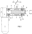
- An electrical switching device for a change gearbox A motor vehicle initially consists of a direct current motor 1 with a directly flanged reduction gear 2 and an output shaft 3.
- the reduction gear 2 is a position or angle sensor 4 assigned in connection with a corresponding electronic control device to control the Electric motor 1 monitors.
- the output shaft 3 is in a manner not shown in detail and connected with a threaded spindle 5, or with this one piece.
- a threaded spindle 5 On the threaded spindle 5 is a threaded nut 6 arranged a radially projecting shift finger 7 carries and in a linear guide 8 against rotation held but axially movable.
- the linear guide 8 can in a particularly simple manner through a longitudinal slot 9 are formed in a tubular sliding sleeve 10 which inside the mother takes 6.
- a solenoid 11 Adjacent to the end of the reduction gear 2 Threaded spindle 5, a solenoid 11 is arranged with a radial coupling surface 12 is provided with a correspondingly designed counter-coupling surface 13 on the End surface of the sliding sleeve 10 can cooperate.
- radial coupling surfaces 12 and 13 To the Both coupling surfaces 12 and 13 are radial splines provided with a minimum stroke of the sliding sleeve 10 a positive connection to the magnetic coil 11 and thus produce the fixed reduction gear 2.
- a coupling flange 15 rotatably via a wedge 16 and a screw 17 connected to the threaded spindle 5.
- a further magnetic coil 18 is arranged in a rotationally fixed manner, which is provided with a radial coupling surface 19, those with a correspondingly designed radial coupling surface 20 at the opposite end of the sliding sleeve 10 can work together.
- the sliding sleeve is in actual function 10 by switching on the solenoid 18, e.g. in one in Fig. 1 seen to the right shifted position in which radial coupling surfaces 19 and 20 a rotationally fixed connection between the threaded spindle 5 via the coupling flange 15 to produce the sliding sleeve 10, whereby the longitudinal slot 9 the shift finger 7 entrained in a rotating movement R. in which he e.g. one of several switching lanes selects the gearbox.
- Fig. 2 are the same components provided with the same reference number and the functional same, but structurally modified components are provided with reference symbols with a dash index.
- this electrical switching device differs compared to the embodiment of FIG. 1 in essentially by the shape of the sliding sleeve 10 ', the Coupling flange 15 'and the solenoid assembly.
- the sliding sleeve 10 ' is at its the Reduction gear 2 adjacent end with an annular groove 21 provided, in which a shift fork 22 engages.
- the Shift fork 22 is provided with the armature 23 of a solenoid 24, which is pushed out of its coil by a spring 25 is and after loading the coil seen in Fig. 2 after is drawn into the solenoid 24 on the left.
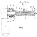
- a flange 26 with a sleeve approach 27 arranged concentrically to the end 3 of the threaded spindle 5 and the sleeve extension 27 receives a magnetic coil 28.
- the sliding sleeve 10 '' is at its left end with a Extension 29 provided with which they are in the sleeve approach 27 extends into it.
- a coil spring 30 inside of the sleeve extension 27 presses the sliding sleeve 10 '' in Fig. 3 seen to the right so that it is back with the coupling flange 15 '' in a non-rotatable connection.
- the radial coupling surfaces 19 '' and 20 '' are the radial coupling surfaces 19 '' and 20 '', however, with synchronized tapering Mistake.
- the sliding sleeve 10 '' is on its other side with the Provide sleeve extension 29 and adjacent to the sleeve extension 29 is on an annular shoulder 31 of the sliding sleeve 10 '' Coupling teeth 13 '' in the manner of a synchronous point educated. In a similar way there is a on the sleeve extension 27 Coupling teeth 12 '' formed.
- FIGS. 1 to 3 of an inventive electrical switching device only expedient embodiments, but it goes without saying that the shape of the linear guide for the threaded nut and the shape of the radial coupling surfaces with their positive coupling gears by a specialist in one Variety of useful constructions can be modified can without the scope of protection of the present Invention is left.
- the essential and the particular advantage of the present invention lies in the fact that both movements, both the rotating movement and the linear movement by the direct derivation from that of one Electric motor driven threaded spindle in its force curve can be controlled very precisely and variably in the desired manner can, so that the corresponding actuation of e.g. Synchronizers in a change gearbox with the corresponding adapted forces can take place.
Landscapes
- Engineering & Computer Science (AREA)
- General Engineering & Computer Science (AREA)
- Mechanical Engineering (AREA)
- Gear-Shifting Mechanisms (AREA)
Description
- Fig. 1
- eine Ausführungsform einer elektrischen Schaltvorrichtung;
- Fig. 2
- eine weitere Ausführungform einer elektrischen Schaltvorrichtung und
- Fig. 3
- eine andere Ausführungsform der elektrischen Schaltvorrichtung gemäß der Erfindung.
Claims (3)
- Elektrische Schaltvorrichtung für Wechselgetriebe von Kraftfahrzeugen, mit einem mit den Gangschaltelementen des Wechselgetriebes zusammenwirkenden, in zwei erforderlichen, im wesentlichen quer zueinander verlaufenden Schaltbewegungen (R und L) bewegbaren Getriebeschaltgliedern, wobei eine lineare Bewegung (L) von einem Elektromotor (1), der eine Gewindespindel (5) mit einer darauf angeordneten, über eine Linearführung (8) gegen Drehung festgehaltenen und axial geführten Mutter (6) kontrolliert dreht, bereitgestellt wird, undauch eine drehende Bewegung (R) von der Gewindespindel (5) abgeleitet wird, indem zwischen der Gewindespindel (5) und der Linearführung (8) der Mutter (6) über eine Kupplung (19/20) eine zeitweilige, kontrollierte, drehfeste Verbindung herstellbar ist, dadurch gekennzeichnet, daßdie Linearführung (8) der Mutter in Form einer auf der Gewindespindel (5) begrenzt axial bewegbar und drehbar angeordneten Verschiebemuffe (10) ausgebildet ist, die an ihren Enden radiale Kupplungsflächen (13 und 20) aufweist, über die sie wechselweise miteiner am Untersetzungsgetriebe (2) vorgesehenen radialen Kupplungsfläche (12) stationär festgehalten oder über eine an einem mit der Gewindespindel (5) drehfest verbundenen Kupplungsflansch (15) vorgesehenen radialen Kupplungsfläche (19) drehfest mit der Gewindespindel (5) verbindbar ist und wobeidie Kupplungsflächen (12 und 19) unmittelbar benachbart zu Magnetspulen (11 und 18) angeordnet sind.
- Elektrische Schaltvorrichtung für Wechselgetriebe von Kraftfahrzeugen, mit einem mit den Gangschaltelementen des Wechselgetriebes zusammenwirkenden, in zwei erforderlichen, im wesentlichen quer zueinander verlaufenden Schaltbewegungen (R und L) bewegbaren Getriebeschaltgliedern, wobei eine lineare Bewegung (L) von einem Elektromotor (1), der eine Gewindespindel (5) mit einer darauf angeordneten, über eine Linearführung (8) gegen Drehung festgehaltenen und axial geführten Mutter (6) kontrolliert dreht, bereitgestellt wird, undauch eine drehende Bewegung (R) von der Gewindespindel (5) abgeleitet wird, indem zwischen der Gewindespindel (5) und der Linearführung (8) der Mutter (6) über eine Kupplung (19/20) eine zeitweilige, kontrollierte, drehfeste Verbindung herstellbar ist, dadurch gekennzeichnet, daßdie Linearführung (8) der Mutter in Form einer auf der Gewindespindel (5) begrenzt axial bewegbar und drehbar angeordneten Verschiebemuffe (10') ausgebildet ist, die an ihren Enden radiale Kupplungsflächen (13 und 20) aufweist, über die sie wechselweise miteiner am Untersetzungsgetriebe (2) vorgesehenen radialen Kupplungsfläche (12) stationär festgehalten oder über eine an einem mit der Gewindespindel (5) drehfest verbundenen Kupplungsflansch (15) vorgesehenen radialen Kupplungsfläche (19) drehfest mit der Gewindespindel (5) verbindbar ist und wobeidie Verschiebemuffe (10') an ihrem einen Ende eine Ringnut (21) aufweist, in die eine Schaltgabel (22) eingreift, die unmittelbar von dem Anker (23) eines Elektromagneten (24) betätigbar ist.
- Elektrische Schaltvorrichtung für Wechselgetriebe von Kraftfahrzeugen, mit einem mit den Gangschaltelementen des Wechselgetriebes zusammenwirkenden, in zwei erforderlichen, im wesentlichen quer zueinander verlaufenden Schaltbewegungen (R und L) bewegbaren Getriebeschaltgliedern, wobei eine lineare Bewegung (L) von einem Elektromotor (1), der eine Gewindespindel (5) mit einer darauf angeordneten, über eine Linearführung (8) gegen Drehung festgehaltenen und axial geführten Mutter (6) kontrolliert dreht, bereitgestellt wird, undauch eine drehende Bewegung (R) von der Gewindespindel (5) abgeleitet wird, indem zwischen der Gewindespindel (5) und der Linearführung (8) der Mutter (6) über eine Kupplung (19/20) eine zeitweilige, kontrollierte, drehfeste Verbindung herstellbar ist, dadurch gekennzeichnet, daßdie Linearführung (8) der Mutter (6) in Form einer auf der Gewindespindel (5) begrenzt axial bewegbar und drehbar angeordneten Verschiebemuffe (10'') ausgebildet ist, die an ihren Enden Kupplungsverzahnungen (20'' und 13'') aufweist, über die sie wechselweise miteiner an einem am Untersetzungsgetriebe (2) festgelegten Hülsenansatz (27) vorgesehenen Kupplungsverzahnung (12'') stationär festgehalten oder über an einem mit der Gewindespindel (5) drehfest verbundenen Kupplungsflansch (15'') vorgesehenen radialen Kupplungsverzahnungen (19'' und 20''), die nach Art einer Synchronanspitzung ausgebildet sind, mit der Gewindespindel (5) verbindbar ist und wobeidie Verschiebemuffe (10'') mit einem Teil (29) unmittelbar den Anker eines Elektromagneten (28) bildet.
Applications Claiming Priority (2)
| Application Number | Priority Date | Filing Date | Title |
|---|---|---|---|
| DE19527893 | 1995-07-29 | ||
| DE19527893A DE19527893C1 (de) | 1995-07-29 | 1995-07-29 | Elektrische Schaltvorrichtung für Wechselgetriebe von Kraftfahrzeugen |
Publications (2)
| Publication Number | Publication Date |
|---|---|
| EP0757193A1 EP0757193A1 (de) | 1997-02-05 |
| EP0757193B1 true EP0757193B1 (de) | 1998-12-02 |
Family
ID=7768189
Family Applications (1)
| Application Number | Title | Priority Date | Filing Date |
|---|---|---|---|
| EP96111404A Expired - Lifetime EP0757193B1 (de) | 1995-07-29 | 1996-07-16 | Elektrische Schaltvorrichtung für Wechselgetriebe von Kraftfahrzeugen |
Country Status (4)
| Country | Link |
|---|---|
| US (1) | US5689997A (de) |
| EP (1) | EP0757193B1 (de) |
| JP (1) | JPH09112688A (de) |
| DE (2) | DE19527893C1 (de) |
Families Citing this family (69)
| Publication number | Priority date | Publication date | Assignee | Title |
|---|---|---|---|---|
| DE19713423C5 (de) * | 1996-04-03 | 2015-11-26 | Schaeffler Technologies AG & Co. KG | Vorrichtung und Verfahren zur Betätigung eines Getriebes |
| DE19635866C2 (de) * | 1996-09-04 | 1998-07-23 | Daimler Benz Ag | Schaltvorrichtung für ein Zahnräderwechselgetriebe |
| GB2350164A (en) * | 1996-09-23 | 2000-11-22 | Mannesmann Sachs Ag | Gearbox actuating device having a single actuator that produces angular and axial motion |
| ES2153255B1 (es) * | 1996-09-23 | 2001-09-01 | Fichtel & Sachs Ag | "dispositivo de ajuste de un elemento de salida desplazable en dos clases de movimiento". |
| JP3635385B2 (ja) * | 1996-11-19 | 2005-04-06 | 愛知機械工業株式会社 | 歯車式変速機の自動変速装置 |
| DE19710121C2 (de) * | 1997-03-12 | 1999-09-16 | Adwest Heidemann Einbeck Gmbh | Vorrichtung zum elektromechanischen Schalten eines Gangwechselgetriebes |
| US6467362B2 (en) | 1997-04-17 | 2002-10-22 | Kerk Motion Products, Inc. | Reinforced lead screw with spring biased anti-backlash nut |
| US6422101B2 (en) | 1997-04-17 | 2002-07-23 | Kerk Motion Products, Inc. | Reinforced lead screw with springless anti-backlash nut |
| US5913941A (en) * | 1997-04-17 | 1999-06-22 | Kerk Motion Products, Inc. | Reinforced lead screw |
| US6415673B1 (en) | 1997-04-17 | 2002-07-09 | Kerk Motion Products, Inc. | Reinforced lead screw with anti-backlash nut |
| DE19815257A1 (de) * | 1997-04-18 | 1998-10-22 | Atlas Fahrzeugtechnik Gmbh | Getriebe |
| US5878624A (en) * | 1997-06-06 | 1999-03-09 | Borg-Warner Automotive, Inc. | Single rail shift operator assembly |
| EP1009942B1 (de) | 1997-08-27 | 2002-10-23 | DaimlerChrysler AG | Schaltvorrichtung für ein zahnräderwechselgetriebe |
| DE19748115C2 (de) * | 1997-10-31 | 2000-12-07 | Sican Gmbh | Vorrichtung zum elektromechanischen Schalten eines Gangwechselgetriebes |
| US5937702A (en) * | 1998-04-14 | 1999-08-17 | Kerk Motion Products, Inc. | Spring bias wedge in reinforcing rail |
| US6131478A (en) * | 1999-01-07 | 2000-10-17 | Kerk Motion Products, Inc. | Anti-backlash nut assembly |
| GB0001364D0 (en) * | 2000-01-24 | 2000-03-08 | Luk Getriebe Systeme Gmbh | Gear engagement mechanism |
| DE20010619U1 (de) * | 2000-06-20 | 2001-08-02 | ADWESET Heidemann Einbeck GmbH, 37574 Einbeck | Schaltvorrichtung für ein Fahrzeug-Wechselgetriebe |
| DE10044159B4 (de) | 2000-09-06 | 2009-12-31 | ZF Lemförder GmbH | Vorrichtung zum Umschaltung eines mechanischen Schaltmittels zwischen einem ersten Schaltzustand und wenigstens einem zweiten Schaltzustand |
| FR2813935B1 (fr) * | 2000-09-08 | 2002-11-29 | Renault | Boite de vitesses a actionneur de passage |
| JP4224945B2 (ja) * | 2001-01-22 | 2009-02-18 | いすゞ自動車株式会社 | 変速機のシフトアクチュエータ |
| JP4788092B2 (ja) * | 2001-01-22 | 2011-10-05 | いすゞ自動車株式会社 | 変速操作装置 |
| JP4211244B2 (ja) | 2001-06-18 | 2009-01-21 | いすゞ自動車株式会社 | 変速操作装置 |
| US6892601B2 (en) * | 2001-06-29 | 2005-05-17 | Isuzu Motors Limited | Gear change device |
| JP4788084B2 (ja) * | 2001-08-21 | 2011-10-05 | いすゞ自動車株式会社 | 変速機のシフト操作装置 |
| DE10143325A1 (de) * | 2001-09-05 | 2003-03-20 | Zahnradfabrik Friedrichshafen | Getriebe mit elektromechanischen Getriebesteller |
| JP4756303B2 (ja) | 2001-09-28 | 2011-08-24 | いすゞ自動車株式会社 | 変速操作装置 |
| US7219570B2 (en) * | 2004-02-17 | 2007-05-22 | Kerk Motion Products, Inc. | Long-span lead screw assembly with anti-backlash nut |
| DE102004016903A1 (de) * | 2004-04-06 | 2005-11-10 | Zf Friedrichshafen Ag | Automatgetriebe mit einem am Getriebegehäuse angeordneten Aktuator |
| US7197955B2 (en) * | 2004-04-16 | 2007-04-03 | Stoneridge Control Devices, Inc. | Gearbox shift actuator |
| WO2006047667A2 (en) * | 2004-10-26 | 2006-05-04 | Stoneridge Control Devices, Inc. | Vehicle gear box actuator |
| FR2861152B1 (fr) * | 2004-11-17 | 2008-10-10 | Valeo Embrayages | Ensemble de commande pour boite de vitesses robotisee. |
| CN101107417B (zh) * | 2004-12-14 | 2013-07-17 | 柔性钻井有限公司 | 振动设备 |
| US7617899B1 (en) | 2004-12-28 | 2009-11-17 | Polaris Industries Inc. | Shifting gear system and method |
| DE112006000287A5 (de) * | 2005-02-23 | 2007-10-31 | Luk Lamellen Und Kupplungsbau Beteiligungs Kg | Betätigungsvorrichtung für ein Kraftfahrzeug-Getriebe, sowie Verfahren zur Verminderung oder Vermeidung von massenträgheitsbedingten Steuerungsfehlern bei Gangwechselvorgängen |
| US20070295128A1 (en) * | 2006-05-19 | 2007-12-27 | Erikson Keith W | Lead screw actuator with torsional anti-backlash nut |
| US7845249B2 (en) * | 2006-09-08 | 2010-12-07 | Schaeffler Technologies Gmbh & Co. Kg | Single motor transmission shifting mechanism for a motor vehicle transmission |
| GB2442878A (en) * | 2006-10-13 | 2008-04-16 | Ricardo Uk Ltd | Transmission actuators with axially and rotatably moveable output member |
| US7891265B2 (en) * | 2006-11-16 | 2011-02-22 | Haydon Kerk Motion Solutions, Inc. | Motor assembly with anti-backlash nut and thermal insensitive mechanism |
| JP5217483B2 (ja) * | 2008-02-19 | 2013-06-19 | いすゞ自動車株式会社 | 変速機のインターロック機構 |
| JP5211741B2 (ja) * | 2008-02-19 | 2013-06-12 | いすゞ自動車株式会社 | 変速機の変速操作装置 |
| US20090249910A1 (en) * | 2008-04-04 | 2009-10-08 | Kerk Motion Products, Inc. | Lead screw device |
| CN101328973B (zh) * | 2008-07-25 | 2013-01-09 | 重庆大学 | 双离合器自动变速预换档机构 |
| ES2429411T3 (es) | 2008-09-16 | 2013-11-14 | Valeo Sicherheitssysteme Gmbh | Dispositivo actuador para una transmisión de un automóvil |
| KR100933768B1 (ko) * | 2009-08-31 | 2009-12-24 | 주식회사 인팩 | 리드스크류 축을 이용한 듀얼 클러치 변속기용 작동기 |
| JP5440862B2 (ja) * | 2009-09-01 | 2014-03-12 | 株式会社ジェイテクト | 変速装置 |
| KR101047649B1 (ko) * | 2009-11-12 | 2011-07-07 | 현대자동차주식회사 | 자동화 수동변속기의 변속장치 |
| JP5472729B2 (ja) * | 2010-02-24 | 2014-04-16 | 株式会社ジェイテクト | 変速装置 |
| JP5440861B2 (ja) | 2010-03-24 | 2014-03-12 | 株式会社ジェイテクト | 変速機駆動装置 |
| KR101251503B1 (ko) * | 2010-12-01 | 2013-04-05 | 현대자동차주식회사 | 수동변속기용 변속 조작기구 |
| JP6116280B2 (ja) * | 2012-08-10 | 2017-04-19 | アイシン・エーアイ株式会社 | 自動変速機のシフト操作装置 |
| DE112014001017A5 (de) * | 2013-02-27 | 2015-11-05 | Schaeffler Technologies AG & Co. KG | Betätigungseinrichtung für ein Kraftfahrzeug |
| CN103206529A (zh) * | 2013-04-07 | 2013-07-17 | 无锡金田元丰科技股份有限公司 | 直线移动缓冲式变速操纵机构及自动变速装置 |
| CN103470753B (zh) * | 2013-09-29 | 2015-11-18 | 长城汽车股份有限公司 | Amt变速器及用于amt变速器的选挡换挡组件 |
| JP6224517B2 (ja) * | 2014-05-09 | 2017-11-01 | 京浜精密工業株式会社 | 変速操作機構 |
| US9458895B2 (en) * | 2014-12-16 | 2016-10-04 | American Axle & Manufacturing, Inc. | Lead screw actuator having axially movable plunger with compliance in both axial directions |
| FR3035467B1 (fr) * | 2015-04-23 | 2019-03-22 | Valeo Embrayages | Actionneur pour boite de vitesses |
| DE102015118952A1 (de) * | 2015-11-05 | 2017-05-11 | Knorr-Bremse Systeme für Nutzfahrzeuge GmbH | Getriebestelleinrichtung für ein automatisiertes Schaltgetriebe eines Fahrzeuges |
| CN105570451B (zh) * | 2016-01-06 | 2017-11-17 | 重庆幻速汽车配件有限公司 | 一个电机的选换挡执行机构 |
| CN106321812B (zh) * | 2016-08-31 | 2018-08-31 | 上海易巴汽车动力系统有限公司 | 一种通用型amt电机选换挡机构 |
| DE102017105100B4 (de) * | 2016-12-21 | 2019-05-29 | Schaeffler Technologies AG & Co. KG | Kugelgewindetrieb und Verfahren zur Herstellung eines Kugelgewindetriebs |
| US10415681B2 (en) * | 2017-01-06 | 2019-09-17 | Team Industries, Inc. | Linear actuator |
| KR101784875B1 (ko) * | 2017-07-11 | 2017-10-12 | 드라이브텍 주식회사 | 전기자동차용 액추에이터 시스템 |
| EP3530994B1 (de) * | 2018-02-21 | 2020-09-30 | Ningbo Geely Automobile Research & Development Co. Ltd. | Schaltvorrichtung |
| IT201800006625A1 (it) * | 2018-06-25 | 2019-12-25 | Dispositivo di azionamento elettrico per un albero di comando di un cambio servocomandato | |
| KR20210006035A (ko) * | 2019-07-08 | 2021-01-18 | 현대자동차주식회사 | 변속기의 변속 액츄에이터 |
| EP3828445A1 (de) * | 2019-11-27 | 2021-06-02 | KNORR-BREMSE Systeme für Nutzfahrzeuge GmbH | Aktuatoranordnung für ein getriebe |
| EP4088047B1 (de) | 2020-01-09 | 2025-03-12 | Stoneridge Control Devices, Inc. | Betätigungsmodul für eine getriebeanordnung |
| WO2022208522A1 (en) * | 2021-03-30 | 2022-10-06 | Tvs Motor Company Limited | A powertrain for a vehicle |
Family Cites Families (11)
| Publication number | Priority date | Publication date | Assignee | Title |
|---|---|---|---|---|
| DE870501C (de) * | 1941-06-24 | 1953-03-16 | Daimler Benz Ag | Schaltvorrichtung, insbesondere fuer Kraftfahrzeuge |
| DE1139758B (de) * | 1956-07-20 | 1962-11-15 | Engineering Res & Applic Ltd | Elektrische Steuer- und Gangschaltvorrichtung fuer ein Wechselgetriebe von Kraftfahrzeugen |
| US4291586A (en) * | 1980-02-19 | 1981-09-29 | General Motors Corporation | Shift control mechanism for a countershaft transmission |
| US4449416A (en) * | 1981-09-04 | 1984-05-22 | J. I. Case Company | Transmission control system |
| JPS58180327A (ja) * | 1982-04-17 | 1983-10-21 | Diesel Kiki Co Ltd | 自動変速機用位置制御装置 |
| JPH0625593B2 (ja) * | 1987-09-29 | 1994-04-06 | いすゞ自動車株式会社 | 変速機制御装置 |
| US5205179A (en) * | 1990-07-21 | 1993-04-27 | Ina Walzlager Schaeffler Kg | Speed changing device |
| DE4137142A1 (de) * | 1991-11-12 | 1993-05-13 | Zahnradfabrik Friedrichshafen | Schalteinrichtung fuer oedie schaltungsbetaetigung von mehrstufenschaltgetrieben fuer kraftfahrzeuge |
| US5219391A (en) * | 1991-12-06 | 1993-06-15 | Eaton Corporation | Transmission shifter having automatic adjustment of control parameters |
| US5357822A (en) * | 1993-04-13 | 1994-10-25 | Eaton Corporation | Transmission shifting mechanism and force attenuator therefor |
| DE4325739A1 (de) * | 1993-07-31 | 1995-02-02 | Zahnradfabrik Friedrichshafen | Schaltvorrichtung für mehrstufige Schaltgetriebe |
-
1995
- 1995-07-29 DE DE19527893A patent/DE19527893C1/de not_active Expired - Fee Related
-
1996
- 1996-07-16 EP EP96111404A patent/EP0757193B1/de not_active Expired - Lifetime
- 1996-07-16 DE DE59600891T patent/DE59600891D1/de not_active Expired - Fee Related
- 1996-07-24 US US08/685,735 patent/US5689997A/en not_active Expired - Fee Related
- 1996-07-26 JP JP8197689A patent/JPH09112688A/ja active Pending
Also Published As
| Publication number | Publication date |
|---|---|
| EP0757193A1 (de) | 1997-02-05 |
| DE19527893C1 (de) | 1996-10-31 |
| DE59600891D1 (de) | 1999-01-14 |
| US5689997A (en) | 1997-11-25 |
| JPH09112688A (ja) | 1997-05-02 |
Similar Documents
| Publication | Publication Date | Title |
|---|---|---|
| DE19527893C1 (de) | Elektrische Schaltvorrichtung für Wechselgetriebe von Kraftfahrzeugen | |
| DE69707058T2 (de) | Getriebeschaltvorrichtung mit Kugel-Rampen-Betätigungseinrichtung | |
| EP0611427B1 (de) | Schalteinrichtung für die schaltungsbetätigung von mehrstufenschaltgetrieben für kraftfahrzeuge | |
| EP1257752B1 (de) | Elektromagnetische schalteinrichtung | |
| DE3331223A1 (de) | Gangschaltanordnung fuer ein kraftfahrzeug | |
| DE3331266A1 (de) | Gangschaltanordnung fuer ein kraftfahrzeug | |
| DE19628642C9 (de) | Elektromechanische Schaltvorrichtung für Wechselgetriebe von Kraftfahrzeugen | |
| DE2930151A1 (de) | Gangwahlmechanismus und diesen enthaltendes getriebe | |
| EP2232107B1 (de) | Schaltvorrichtung für mehrstufenschaltgetriebe von kraftfahrzeugen | |
| DE19635866C2 (de) | Schaltvorrichtung für ein Zahnräderwechselgetriebe | |
| DE19543645A1 (de) | Vorrichtung zum Schalten von Fahrzeuggetrieben | |
| DE19628642A1 (de) | Elektromechanische Schaltvorrichtung für Wechselgetriebe von Kraftfahrzeugen | |
| DE19842532A1 (de) | Schaltvorrichtung | |
| EP0849506A1 (de) | Federelement zur Wählkrafterzeugung für ein mehrgängiges Zahnräderwechselgetriebe | |
| DE2534565B2 (de) | Automatische elektrisch geteuerte Schaltvorricthung für ein Zahnradwechselgetriebe für Fahrzeuge | |
| DE69810030T2 (de) | Automatisierte Schaltvorrichtung für ein Gangwechselgetriebe | |
| EP1333201A2 (de) | Schaltvorrichtung eines Getriebes | |
| DE19933499A1 (de) | Elektrisch betriebene Schaltvorrichtung | |
| EP0636819B1 (de) | Schaltvorrichtung für mehrstufige Schaltgetriebe | |
| DE2341199A1 (de) | Schalteinrichtung fuer mechanische wechselgetriebe von kraftfahrzeugen | |
| EP0770802A2 (de) | Schalteinrichtung für Kraftfahrzeug-Wechselgetriebe mit Abbremsung der Eingangswelle beim Einschalten des Rückwärtsganges | |
| DE602004000326T2 (de) | Steuervorrichtung für ein automatisiertes Handschaltgetriebe mit einer rotierenden Hülse und dem zugehörigen Schaltverfahren | |
| DE102012214430A1 (de) | Schalteinrichtung für ein Schaltgetriebe | |
| DE102005039559B4 (de) | Elektromechanische Getriebesteuerung | |
| DE4333726A1 (de) | Antriebseinheit zur Betätigung mehrerer Verstelleinrichtungen |
Legal Events
| Date | Code | Title | Description |
|---|---|---|---|
| PUAI | Public reference made under article 153(3) epc to a published international application that has entered the european phase |
Free format text: ORIGINAL CODE: 0009012 |
|
| AK | Designated contracting states |
Kind code of ref document: A1 Designated state(s): DE FR GB |
|
| 17P | Request for examination filed |
Effective date: 19961218 |
|
| 17Q | First examination report despatched |
Effective date: 19970523 |
|
| GRAG | Despatch of communication of intention to grant |
Free format text: ORIGINAL CODE: EPIDOS AGRA |
|
| GRAG | Despatch of communication of intention to grant |
Free format text: ORIGINAL CODE: EPIDOS AGRA |
|
| GRAH | Despatch of communication of intention to grant a patent |
Free format text: ORIGINAL CODE: EPIDOS IGRA |
|
| GRAH | Despatch of communication of intention to grant a patent |
Free format text: ORIGINAL CODE: EPIDOS IGRA |
|
| RAP1 | Party data changed (applicant data changed or rights of an application transferred) |
Owner name: FORD GLOBAL TECHNOLOGIES, INC. |
|
| GRAA | (expected) grant |
Free format text: ORIGINAL CODE: 0009210 |
|
| AK | Designated contracting states |
Kind code of ref document: B1 Designated state(s): DE FR GB |
|
| GBT | Gb: translation of ep patent filed (gb section 77(6)(a)/1977) |
Effective date: 19981204 |
|
| REF | Corresponds to: |
Ref document number: 59600891 Country of ref document: DE Date of ref document: 19990114 |
|
| ET | Fr: translation filed | ||
| PLBE | No opposition filed within time limit |
Free format text: ORIGINAL CODE: 0009261 |
|
| STAA | Information on the status of an ep patent application or granted ep patent |
Free format text: STATUS: NO OPPOSITION FILED WITHIN TIME LIMIT |
|
| 26N | No opposition filed | ||
| REG | Reference to a national code |
Ref country code: GB Ref legal event code: IF02 |
|
| REG | Reference to a national code |
Ref country code: GB Ref legal event code: 732E |
|
| REG | Reference to a national code |
Ref country code: FR Ref legal event code: TP |
|
| PGFP | Annual fee paid to national office [announced via postgrant information from national office to epo] |
Ref country code: GB Payment date: 20060614 Year of fee payment: 11 |
|
| PGFP | Annual fee paid to national office [announced via postgrant information from national office to epo] |
Ref country code: FR Payment date: 20060705 Year of fee payment: 11 |
|
| PGFP | Annual fee paid to national office [announced via postgrant information from national office to epo] |
Ref country code: DE Payment date: 20060731 Year of fee payment: 11 |
|
| GBPC | Gb: european patent ceased through non-payment of renewal fee |
Effective date: 20070716 |
|
| PG25 | Lapsed in a contracting state [announced via postgrant information from national office to epo] |
Ref country code: DE Free format text: LAPSE BECAUSE OF NON-PAYMENT OF DUE FEES Effective date: 20080201 |
|
| PG25 | Lapsed in a contracting state [announced via postgrant information from national office to epo] |
Ref country code: GB Free format text: LAPSE BECAUSE OF NON-PAYMENT OF DUE FEES Effective date: 20070716 |
|
| REG | Reference to a national code |
Ref country code: FR Ref legal event code: ST Effective date: 20080331 |
|
| PG25 | Lapsed in a contracting state [announced via postgrant information from national office to epo] |
Ref country code: FR Free format text: LAPSE BECAUSE OF NON-PAYMENT OF DUE FEES Effective date: 20070731 |