EP4088047B1 - Betätigungsmodul für eine getriebeanordnung - Google Patents
Betätigungsmodul für eine getriebeanordnung Download PDFInfo
- Publication number
- EP4088047B1 EP4088047B1 EP21703107.9A EP21703107A EP4088047B1 EP 4088047 B1 EP4088047 B1 EP 4088047B1 EP 21703107 A EP21703107 A EP 21703107A EP 4088047 B1 EP4088047 B1 EP 4088047B1
- Authority
- EP
- European Patent Office
- Prior art keywords
- fork
- assembly
- actuator module
- driver
- gearbox
- Prior art date
- Legal status (The legal status is an assumption and is not a legal conclusion. Google has not performed a legal analysis and makes no representation as to the accuracy of the status listed.)
- Active
Links
Images


Classifications
-
- F—MECHANICAL ENGINEERING; LIGHTING; HEATING; WEAPONS; BLASTING
- F16—ENGINEERING ELEMENTS AND UNITS; GENERAL MEASURES FOR PRODUCING AND MAINTAINING EFFECTIVE FUNCTIONING OF MACHINES OR INSTALLATIONS; THERMAL INSULATION IN GENERAL
- F16H—GEARING
- F16H25/00—Gearings comprising primarily only cams, cam-followers and screw-and-nut mechanisms
- F16H25/18—Gearings comprising primarily only cams, cam-followers and screw-and-nut mechanisms for conveying or interconverting oscillating or reciprocating motions
- F16H25/20—Screw mechanisms
-
- F—MECHANICAL ENGINEERING; LIGHTING; HEATING; WEAPONS; BLASTING
- F16—ENGINEERING ELEMENTS AND UNITS; GENERAL MEASURES FOR PRODUCING AND MAINTAINING EFFECTIVE FUNCTIONING OF MACHINES OR INSTALLATIONS; THERMAL INSULATION IN GENERAL
- F16H—GEARING
- F16H61/00—Control functions within control units of change-speed- or reversing-gearings for conveying rotary motion ; Control of exclusively fluid gearing, friction gearing, gearings with endless flexible members or other particular types of gearing
- F16H61/0003—Arrangement or mounting of elements of the control apparatus, e.g. valve assemblies or snapfittings of valves; Arrangements of the control unit on or in the transmission gearbox
- F16H61/0006—Electronic control units for transmission control, e.g. connectors, casings or circuit boards
-
- F—MECHANICAL ENGINEERING; LIGHTING; HEATING; WEAPONS; BLASTING
- F16—ENGINEERING ELEMENTS AND UNITS; GENERAL MEASURES FOR PRODUCING AND MAINTAINING EFFECTIVE FUNCTIONING OF MACHINES OR INSTALLATIONS; THERMAL INSULATION IN GENERAL
- F16H—GEARING
- F16H61/00—Control functions within control units of change-speed- or reversing-gearings for conveying rotary motion ; Control of exclusively fluid gearing, friction gearing, gearings with endless flexible members or other particular types of gearing
- F16H61/26—Generation or transmission of movements for final actuating mechanisms
- F16H61/28—Generation or transmission of movements for final actuating mechanisms with at least one movement of the final actuating mechanism being caused by a non-mechanical force, e.g. power-assisted
- F16H61/32—Electric motors , actuators or related electrical control means therefor
-
- F—MECHANICAL ENGINEERING; LIGHTING; HEATING; WEAPONS; BLASTING
- F16—ENGINEERING ELEMENTS AND UNITS; GENERAL MEASURES FOR PRODUCING AND MAINTAINING EFFECTIVE FUNCTIONING OF MACHINES OR INSTALLATIONS; THERMAL INSULATION IN GENERAL
- F16H—GEARING
- F16H63/00—Control outputs from the control unit to change-speed- or reversing-gearings for conveying rotary motion or to other devices than the final output mechanism
-
- F—MECHANICAL ENGINEERING; LIGHTING; HEATING; WEAPONS; BLASTING
- F16—ENGINEERING ELEMENTS AND UNITS; GENERAL MEASURES FOR PRODUCING AND MAINTAINING EFFECTIVE FUNCTIONING OF MACHINES OR INSTALLATIONS; THERMAL INSULATION IN GENERAL
- F16H—GEARING
- F16H25/00—Gearings comprising primarily only cams, cam-followers and screw-and-nut mechanisms
- F16H25/18—Gearings comprising primarily only cams, cam-followers and screw-and-nut mechanisms for conveying or interconverting oscillating or reciprocating motions
- F16H25/20—Screw mechanisms
- F16H2025/2031—Actuator casings
-
- F—MECHANICAL ENGINEERING; LIGHTING; HEATING; WEAPONS; BLASTING
- F16—ENGINEERING ELEMENTS AND UNITS; GENERAL MEASURES FOR PRODUCING AND MAINTAINING EFFECTIVE FUNCTIONING OF MACHINES OR INSTALLATIONS; THERMAL INSULATION IN GENERAL
- F16H—GEARING
- F16H25/00—Gearings comprising primarily only cams, cam-followers and screw-and-nut mechanisms
- F16H25/18—Gearings comprising primarily only cams, cam-followers and screw-and-nut mechanisms for conveying or interconverting oscillating or reciprocating motions
- F16H25/20—Screw mechanisms
- F16H2025/2062—Arrangements for driving the actuator
- F16H2025/2084—Perpendicular arrangement of drive motor to screw axis
-
- F—MECHANICAL ENGINEERING; LIGHTING; HEATING; WEAPONS; BLASTING
- F16—ENGINEERING ELEMENTS AND UNITS; GENERAL MEASURES FOR PRODUCING AND MAINTAINING EFFECTIVE FUNCTIONING OF MACHINES OR INSTALLATIONS; THERMAL INSULATION IN GENERAL
- F16H—GEARING
- F16H25/00—Gearings comprising primarily only cams, cam-followers and screw-and-nut mechanisms
- F16H25/18—Gearings comprising primarily only cams, cam-followers and screw-and-nut mechanisms for conveying or interconverting oscillating or reciprocating motions
- F16H25/20—Screw mechanisms
- F16H2025/2062—Arrangements for driving the actuator
- F16H2025/209—Arrangements for driving the actuator using worm gears
-
- F—MECHANICAL ENGINEERING; LIGHTING; HEATING; WEAPONS; BLASTING
- F16—ENGINEERING ELEMENTS AND UNITS; GENERAL MEASURES FOR PRODUCING AND MAINTAINING EFFECTIVE FUNCTIONING OF MACHINES OR INSTALLATIONS; THERMAL INSULATION IN GENERAL
- F16H—GEARING
- F16H61/00—Control functions within control units of change-speed- or reversing-gearings for conveying rotary motion ; Control of exclusively fluid gearing, friction gearing, gearings with endless flexible members or other particular types of gearing
- F16H61/26—Generation or transmission of movements for final actuating mechanisms
- F16H61/28—Generation or transmission of movements for final actuating mechanisms with at least one movement of the final actuating mechanism being caused by a non-mechanical force, e.g. power-assisted
- F16H2061/2884—Screw-nut devices
-
- F—MECHANICAL ENGINEERING; LIGHTING; HEATING; WEAPONS; BLASTING
- F16—ENGINEERING ELEMENTS AND UNITS; GENERAL MEASURES FOR PRODUCING AND MAINTAINING EFFECTIVE FUNCTIONING OF MACHINES OR INSTALLATIONS; THERMAL INSULATION IN GENERAL
- F16H—GEARING
- F16H61/00—Control functions within control units of change-speed- or reversing-gearings for conveying rotary motion ; Control of exclusively fluid gearing, friction gearing, gearings with endless flexible members or other particular types of gearing
- F16H61/26—Generation or transmission of movements for final actuating mechanisms
- F16H61/28—Generation or transmission of movements for final actuating mechanisms with at least one movement of the final actuating mechanism being caused by a non-mechanical force, e.g. power-assisted
- F16H2061/2892—Generation or transmission of movements for final actuating mechanisms with at least one movement of the final actuating mechanism being caused by a non-mechanical force, e.g. power-assisted other gears, e.g. worm gears, for transmitting rotary motion to the output mechanism
-
- F—MECHANICAL ENGINEERING; LIGHTING; HEATING; WEAPONS; BLASTING
- F16—ENGINEERING ELEMENTS AND UNITS; GENERAL MEASURES FOR PRODUCING AND MAINTAINING EFFECTIVE FUNCTIONING OF MACHINES OR INSTALLATIONS; THERMAL INSULATION IN GENERAL
- F16H—GEARING
- F16H63/00—Control outputs from the control unit to change-speed- or reversing-gearings for conveying rotary motion or to other devices than the final output mechanism
- F16H2063/005—Preassembled gear shift units for mounting on gear case
-
- F—MECHANICAL ENGINEERING; LIGHTING; HEATING; WEAPONS; BLASTING
- F16—ENGINEERING ELEMENTS AND UNITS; GENERAL MEASURES FOR PRODUCING AND MAINTAINING EFFECTIVE FUNCTIONING OF MACHINES OR INSTALLATIONS; THERMAL INSULATION IN GENERAL
- F16H—GEARING
- F16H63/00—Control outputs from the control unit to change-speed- or reversing-gearings for conveying rotary motion or to other devices than the final output mechanism
- F16H63/02—Final output mechanisms therefor; Actuating means for the final output mechanisms
- F16H63/30—Constructional features of the final output mechanisms
- F16H63/304—Constructional features of the final output mechanisms the final output mechanisms comprising elements moved by electrical or magnetic force
- F16H2063/3063—Constructional features of the final output mechanisms the final output mechanisms comprising elements moved by electrical or magnetic force using screw devices
-
- F—MECHANICAL ENGINEERING; LIGHTING; HEATING; WEAPONS; BLASTING
- F16—ENGINEERING ELEMENTS AND UNITS; GENERAL MEASURES FOR PRODUCING AND MAINTAINING EFFECTIVE FUNCTIONING OF MACHINES OR INSTALLATIONS; THERMAL INSULATION IN GENERAL
- F16H—GEARING
- F16H63/00—Control outputs from the control unit to change-speed- or reversing-gearings for conveying rotary motion or to other devices than the final output mechanism
- F16H63/02—Final output mechanisms therefor; Actuating means for the final output mechanisms
- F16H63/30—Constructional features of the final output mechanisms
- F16H63/304—Constructional features of the final output mechanisms the final output mechanisms comprising elements moved by electrical or magnetic force
- F16H2063/3066—Constructional features of the final output mechanisms the final output mechanisms comprising elements moved by electrical or magnetic force using worm gears
-
- F—MECHANICAL ENGINEERING; LIGHTING; HEATING; WEAPONS; BLASTING
- F16—ENGINEERING ELEMENTS AND UNITS; GENERAL MEASURES FOR PRODUCING AND MAINTAINING EFFECTIVE FUNCTIONING OF MACHINES OR INSTALLATIONS; THERMAL INSULATION IN GENERAL
- F16H—GEARING
- F16H63/00—Control outputs from the control unit to change-speed- or reversing-gearings for conveying rotary motion or to other devices than the final output mechanism
- F16H63/02—Final output mechanisms therefor; Actuating means for the final output mechanisms
- F16H63/30—Constructional features of the final output mechanisms
- F16H2063/3079—Shift rod assembly, e.g. supporting, assembly or manufacturing of shift rails or rods; Special details thereof
-
- F—MECHANICAL ENGINEERING; LIGHTING; HEATING; WEAPONS; BLASTING
- F16—ENGINEERING ELEMENTS AND UNITS; GENERAL MEASURES FOR PRODUCING AND MAINTAINING EFFECTIVE FUNCTIONING OF MACHINES OR INSTALLATIONS; THERMAL INSULATION IN GENERAL
- F16H—GEARING
- F16H57/00—General details of gearing
- F16H57/02—Gearboxes; Mounting gearing therein
- F16H57/031—Gearboxes; Mounting gearing therein characterised by covers or lids for gearboxes
-
- F—MECHANICAL ENGINEERING; LIGHTING; HEATING; WEAPONS; BLASTING
- F16—ENGINEERING ELEMENTS AND UNITS; GENERAL MEASURES FOR PRODUCING AND MAINTAINING EFFECTIVE FUNCTIONING OF MACHINES OR INSTALLATIONS; THERMAL INSULATION IN GENERAL
- F16H—GEARING
- F16H61/00—Control functions within control units of change-speed- or reversing-gearings for conveying rotary motion ; Control of exclusively fluid gearing, friction gearing, gearings with endless flexible members or other particular types of gearing
- F16H61/02—Control functions within control units of change-speed- or reversing-gearings for conveying rotary motion ; Control of exclusively fluid gearing, friction gearing, gearings with endless flexible members or other particular types of gearing characterised by the signals used
- F16H61/0202—Control functions within control units of change-speed- or reversing-gearings for conveying rotary motion ; Control of exclusively fluid gearing, friction gearing, gearings with endless flexible members or other particular types of gearing characterised by the signals used the signals being electric
-
- F—MECHANICAL ENGINEERING; LIGHTING; HEATING; WEAPONS; BLASTING
- F16—ENGINEERING ELEMENTS AND UNITS; GENERAL MEASURES FOR PRODUCING AND MAINTAINING EFFECTIVE FUNCTIONING OF MACHINES OR INSTALLATIONS; THERMAL INSULATION IN GENERAL
- F16H—GEARING
- F16H63/00—Control outputs from the control unit to change-speed- or reversing-gearings for conveying rotary motion or to other devices than the final output mechanism
- F16H63/02—Final output mechanisms therefor; Actuating means for the final output mechanisms
- F16H63/04—Final output mechanisms therefor; Actuating means for the final output mechanisms a single final output mechanism being moved by a single final actuating mechanism
-
- F—MECHANICAL ENGINEERING; LIGHTING; HEATING; WEAPONS; BLASTING
- F16—ENGINEERING ELEMENTS AND UNITS; GENERAL MEASURES FOR PRODUCING AND MAINTAINING EFFECTIVE FUNCTIONING OF MACHINES OR INSTALLATIONS; THERMAL INSULATION IN GENERAL
- F16H—GEARING
- F16H63/00—Control outputs from the control unit to change-speed- or reversing-gearings for conveying rotary motion or to other devices than the final output mechanism
- F16H63/02—Final output mechanisms therefor; Actuating means for the final output mechanisms
- F16H63/30—Constructional features of the final output mechanisms
- F16H63/304—Constructional features of the final output mechanisms the final output mechanisms comprising elements moved by electrical or magnetic force
Definitions
- the disclosure relates to an actuator module such as a vehicle transmission or other vehicle driveline component.
- Vehicles include a driveline, which is used to transmit rotational drive from the vehicle's power plant to the wheels.
- Typical driveline components include, for example, transmissions, transfer cases, front and rear axles, and drive shafts.
- Many driveline components have a rotatable and/or slidable member that is movable between multiple positions using an actuator during vehicle operation. Examples include transmission and transfer case shift collars and park locks.
- a common challenge in designing driveline components is providing an actuator system that is compact, durable, efficient and cost-effective.
- US 2019/0264753 discloses linear actuator mechanisms for vehicle disconnect/connect systems having a shift fork and a stationary guide rod extending though the shift fork.
- the mechanism includes a drive nut, a drive screw extending through the drive nut, a first spring plate, a second spring plate, and a compression spring positioned between a radially extending portion of the first spring plate and a radially extending portion of the second spring plate.
- a second radially extending portion of the first spring plate and a second radially extending portion of the second spring plate are in contact with the drive nut on axially opposite sides of the drive nut.
- the first and second spring plates, and the spring are moveable axially along the stationary guide rod by the drive nut to compress the compression spring.
- An aspect of the present invention relates to an actuator module set out in claim 1.
- Optional features are set out in the dependent claims.
- An actuator module for a driveline assembly includes, among other things, a cover housing and a fork driving unit supported by the cover housing.
- the fork driving unit includes a fork driver for moving a shift fork and a pusher assembly coupled to the fork driver by spaced apart pusher ends.
- the fork driving unit also includes a drive assembly carried by the pusher assembly to translate the fork driver relative to the cover housing.
- the fork driving unit further includes a spring that biases the pusher assembly and fork driver to a neutral position relative to one another.
- the actuator module includes a fork shaft that is supported by the cover housing.
- the fork driver is slidably supported by the fork shaft between multiple shift positions.
- the drive assembly is arranged parallel to the fork shaft.
- the fork driver includes first and second walls that extend from a central portion and are spaced apart from one another.
- the first and second walls have shaped apertures.
- the pusher ends are received in the shaped apertures to permit the pusher assembly to axially slide relative to the fork driver between the neutral position and a transition position while preventing rotation of the pusher assembly relative to the fork driver.
- the cover housing assembly includes first and second cover portions that enclose the drive assembly.
- the actuator module includes a motor and a gearbox that is coupled to the motor and the drive assembly.
- the motor and the gearbox are arranged between the first and second cover portions.
- the pusher assembly includes first and second pushers that are joined by a drive nut with left-hand and right-hand threads.
- Each of the first and second pushers includes a flange seat that is received in a respective shape aperture of the first and second walls.
- Each of the opposing ends of the spring engages one of the first and second walls and the flange seats and one of the first and second pushers.
- the drive nut has a threaded inner diameter that threadingly engages a threaded shaft of the drive assembly.
- the threaded shaft has first and second ends.
- the first end is coupled to a worm gear of a gearbox.
- the second end is supported by a bracket that is secured to the cover housing.
- the drive assembly has a drive axis and includes a rotary sensor assembly that has a rotary sensor with a sensor axis offset from the drive axis.
- the rotary sensor is operatively coupled to the drive assembly and configured to measure a position of the fork driver.
- the actuator module includes a linear sensor assembly that is mounted to the fork driver and is configured to measure a position of the fork driver.
- the actuator module includes a gearbox that is coupled to a motor and the drive assembly.
- the gearbox has a worm and a worm gear that is mounted to first and second gear housing brackets having an L-shape.
- Each of the first and second gear housing brackets include a mounting flange that is secured to the cover housing.
- the motor is connected to the worm.
- the drive assembly is connected to the worm gear.
- an actuator module for a driveline assembly includes a cover housing, a motor that is supported relative to the cover housing and a fork driving unit that is supported by the cover housing.
- the fork driving unit includes a fork driver and a drive assembly that is configured to translate the fork driver relative to the cover housing.
- a gearbox is coupled to the motor and the drive assembly. The gearbox is supported relative to the cover housing.
- the gearbox has a worm and a worm gear that is mounted to first and second gear housing brackets having an L-shape.
- Each of the first and second gear housing brackets include a mounting flange that is secured to the cover housing.
- first and second gear housing brackets include holes that are configured to receive bushings that support cylindrical ends of the worm and the worm gear.
- the drive assembly includes a threaded shaft with first and second ends.
- the first end is coupled to the worm gear.
- the second end is supported by a bracket that is secured to the cover assembly.
- a bracket supports a worm and a bearing that receives the first end.
- an actuator module for a driveline assembly includes a cover housing, a printed circuit board, a motor that is supported relative to the cover housing and a fork driving unit that is supported by the cover housing.
- the fork driving unit includes a fork driver.
- a sensor is in communication with the printed circuit board and is arranged in relation to the fork driving unit to measure a position of the fork driver.
- the actuator module includes a gearbox that is coupled to the motor and a drive assembly that is configured to translate the fork driver relative to the cover housing.
- a gearbox is supported relative to the cover housing.
- the drive assembly has a drive axis.
- the sensor includes a rotary sensor assembly that has a rotary sensor with a sensor axis offset from the drive axis. The rotary sensor is operatively coupled to the drive assembly and is configured to measure the position of the fork driver.
- the drive assembly includes a threaded shaft.
- the rotary sensor assembly includes a drive pulley that is attached to threaded shaft.
- An anchor pin is mounted to the cover housing to support a follow pulley to which the rotary sensor is mounted.
- a belt interconnects the drive and follow pulleys.
- the senor includes a linear sensor assembly that is mounted to the fork driver and is configured to measure the position of the fork driver.
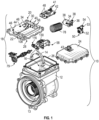
- a driveline assembly 10, shown in Figure 1 includes an actuator module 18 that is used to shift a component within the driveline assembly between multiple positions.
- the driveline assembly 10 is a gearbox, but other driveline components are contemplated, such as a transfer box, or a park lock.
- a shifting member 13, such as a shifting sleeve is arranged within a housing 12 of the driveline assembly 10.
- the shifting sleeve includes a collar having an annular groove (not shown), as is known.
- the actuator module 18 includes a shift fork 14 that cooperates with the shifting member 13 and is received in the collar. Sliding the shift fork 14 axially moves the shifting sleeve between multiple positions corresponding to different transmission gears positions.
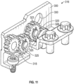
- the actuator module 18 is housed with respect to a cover housing 20 having first and second cover portions 22, 24 that are secured to one another about a gasket 26.
- the first cover portion 22 includes a "wet" first side 28 facing a cavity 16 of the housing 12 that is exposed to lubricant and a "dry" second side 30 facing the second cover portion 24 that is sealed from the lubricant.
- the actuator module 18 contains all the components that are needed to provide shifting to driveline component and can be secured to the housing 12 as a single unit.
- Bosses 44 are provided on the second side 30 and include holes 46.
- a printed circuit board (PCB) 42 is secured to the bosses 44 by fasteners 48. Terminals 41 from the PCB 42 extend to a connector 43 that is carried by the second cover portion 24 when the actuator module 18 is fully assembled.
- the connector 43 receives command signals from the vehicle that control the shifting of the driveline assembly.
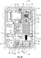
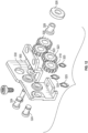
- the fork driving unit 58 cooperates with the drive assembly 79.
- the fork driving unit 58 includes a fork driver 60 that is mounted to a fork shaft 62, which has its opposing ends supported in bosses provided by the first side 28 of the first cover portion 22.
- the fork shaft 62 may be fixed against rotation as it need not rotate during operation.
- the fork driver 60 includes a central portion 63 that supports first and second walls 64, 66 that are spaced apart from one another to form a C-shaped configuration.
- the fork 14 is disposed within the central portion 63. Bores 68 are provided in the central portion 63 and in the fork 14 to slidably support the fork driving unit 58 on the fork shaft 62, which is parallel to the drive assembly 79.
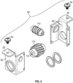
- the gearbox 50 uses interchangeable brackets 52 for simplicity.
- the brackets 52 can be located with respect to one another by complementary dimples and depressions or secured using fasteners.
- the brackets 52 support a worm 110 coupled to a worm gear 112.
- Worm gear 112 includes an opening 114 having a complementary shape to the second end 92 for mating with threaded shaft 90. If desired, holes in the brackets 52 may receive pressed-in bushings to support cylindrical ends of the worm 110 and the worm gear 112. Washers may be used to reduce friction.
- Different sets of worm/worm gears can be used in the gearbox 50.
- the gearbox 50 can be configured to provide a gear reduction ratio of up to 21.
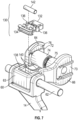
- shaped apertures 70 are provided in each of the first and second walls 64, 66.
- a pusher assembly includes first and second pushers 74, 75 respectively having first and second pusher ends 72, 73 received within respective apertures 70 of the first and second walls 64, 66.
- the first and second walls 64, 66 each include inner surfaces disposed about the aperture 70 to provide a seat 76.
- a spring 78 is arranged between the first and second walls 64, 66 and engage the seats 76 and flange seats of the pusher ends 72, 73. The spring 78 is configured to bias the pusher assembly and the fork driver 60 to a neutral position relative to one another.
- the pusher ends 72, 73 are received within the aperture 70 in a slip fit relationship to permit the pusher assembly to actually slide relative to the fork driver 60 between the neutral position and a transition position while preventing rotation of the pusher assembly relative to the fork driver 60.
- This configuration enables the smooth operation of the actuator module for example during a shifting sequence of the shifting member 13, avoiding jarring engagement of the shifting member 13 with its mating component.
- the drive assembly 79 includes a driving nut 80 having a flange 82.
- a threaded outer diameter 84 of the driving nut 80 secures to complementarily-shaped threaded inner diameter 86 of the spring pusher 74. This enables the pusher assembly to be installed onto the driving nut 80 and about the spring 78 during assembly.
- the driving nut 80 includes a threaded inner diameter 88 that cooperates with a leadscrew or threaded shaft 90 of the drive assembly 79.
- the threaded shaft 90 includes a first end 92 having a feature, such as a square end, that connects to the gearbox 50.
- a bearing 94 supports the first end 92 for rotation with respect to the first cover portion 22.
- the threaded shaft 90 includes a second end 96 supported by a bracket 100 using a lock nut 98 secured to the second end 96.
- the bracket 100 is mounted to the first cover portion 22 along with a reinforcing plate 104 that is secured to the first cover portion 22 by fasteners 106 extending through holes 108 ( Fig. 1 ).
- the rotary sensor assembly 116 measures the rotational position of the drive assembly 79 to determine the position of the shift fork 14.
- the rotary sensor assembly 116 includes a drive pulley 118 mounted to the lock nut 98 at a keyed interface.
- a follow pulley 120 is driven by the drive pulley 118 via a belt 122 providing a 1:1 ratio.
- the follow pulley 120 is supported by the first side 28 of the first cover portion 22 with a pin 124 mounted to a boss.
- a rotary sensor 126 is mounted to the drive pulley 118, and a connector 128 is secured to the pin 124 to capture the drive pulley 118 and rotary sensor 126.
- the drive assembly 79 has a drive axis
- the rotary sensor 126 has a sensor axis offset from the drive axis. This configuration enables the rotary sensor 126 to be located in position remote from the threaded shaft 90 for improved packaging.
- the linear sensor assembly 130 is supported by the fork driving unit 58 to measure the axial position of the shift fork 14.
- the linear sensor assembly 130 includes a sensor holder 132 that is mounted to the central portion 63 of the fork driver 60.
- the sensor holder 132 includes a channel 134 received in a lip 138 of the central portion 63, which takes advantage of the stamped sheet metal features of the fork drive 60. Snaps 136 provided by the sensor holder 132 cooperate with notches 140 in the central portion 63.
- a linear sensor 142 is mounted within the sensor holder 132.
- a separate bracket 200 may be used to house a bearing 206 supporting one end of the threaded shaft 290.
- the bracket 200 includes a first bracket portion 202, which may be cast, secured to the cover housing 20' using a plate 226 and fasteners 228.
- the second bracket portion 204 which may be stamped sheet metal, includes locating pins 205 received in corresponding recesses in the first bracket portion 202 to capture the bearing 206 within a pocket in the first bracket portion 202 using fasteners 214.
- the bearing 206 abuts a shoulder 208 on the threaded shaft 290 and is clamped thereto by a nut 210 freely disposed within an opening 212 in the second bracket portion 204.
- the driving nut 280 includes opposing right-hand and left-hand threads that are threadingly secured to the first and second spring pushers 274, 275, so as to provide a turnbuckle.
- the annular flange 282 includes notches 283 about its periphery so that a tool can be used to adjust the distance between the spring pushers during assembly to ensure flange seats are flush with those of the fork support, which ensures there is no undesired clearances or take-up in the drive assembly. Any motion in the system without movement in the fork 14 may lead to poor performance.
- the bracket 200 is also used to support the gears.
- the worm gear 112' is keyed to the end of the threaded rod 290 as previously described.
- the second bracket portion 204 has a flange 216 with a hole 218 that supports an end of the worm 110' by a first bushing 220, as shown in Figures 10A and 10B .
- the opposite end of the worm 110' is supported by a second bushing 222 that is mounted to the cover housing 20'. Seals 224 in the second bushing 222 isolate the motor from the lubricant in the cavity 16.
- One or more of the gears 320, 323 are supported for rotation relative to the bracket 300 by pins 324 and circlips 325. Having the threaded rod 290 and the rotary sensor assembly 316 supported by a common bracket reduces tolerances in the system.
- a reinforcement plate 400 is secured to end faces of the first and second walls 464, 466 using fasteners 402.
- the reinforcement plate 400 captures the spring pushers and prevents racking of the assembly.
- a fork support 470 is secured to the central portion 463 connecting the first and second walls 464, 466 with fasteners 472, such as rivets or welds, for example. In this way, different fork supports may be selected and secured to a common spring pusher support depending upon the application.
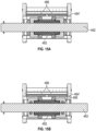
- a bearing assembly 480 supports the fork driver 460 for sliding motion along the fork shaft 462 in applications having increased loads.
- a spacer 482 extends through the fork (14 in the figures).
- Bearing end caps 484 are threaded onto the spacer 482 and clamp about lateral walls 486 of the fork support 470.
- the bearing end caps 484' are bushings, whereas the example bearing end caps 484 illustrated in Figure 15B include rolling elements 488 for increased load capability.
- the example bearing assembly 480 spreads the fork load over a relatively large distance on the fork shaft 462, which provides increased stability under high loads.
Landscapes
- Engineering & Computer Science (AREA)
- General Engineering & Computer Science (AREA)
- Mechanical Engineering (AREA)
- Gear-Shifting Mechanisms (AREA)
- Connection Of Motors, Electrical Generators, Mechanical Devices, And The Like (AREA)
- Gear Transmission (AREA)
- Transmission Devices (AREA)
Claims (7)
- Stellantriebsmodul (18) für eine Kraftübertragungsbaugruppe, das Folgendes umfasst:ein Abdeckungsgehäuse (20),eine Gabelantriebseinheit (58), die durch das Abdeckungsgehäuse (20) getragen wird, wobei die Gabelantriebseinheit (58) Folgendes einschließt:einen Gabelantrieb (60) zum Bewegen einer Schaltgabel,eine Schieberbaugruppe, die durch voneinander beabstandete Schieberenden (72, 73) an den Gabelantrieb (60) gekoppelt ist,eine Antriebsbaugruppe (79), die durch die Schieberbaugruppe getragen wird, um den Gabelantrieb (60) im Verhältnis zu dem Abdeckungsgehäuse (20) zu verschieben, undeine Feder, die dafür konfiguriert ist, die Schieberbaugruppe und den Gabelantrieb (60) in Verhältnis zueinander zu einer neutralen Position vorzuspannen,wobei das Stellantriebsmodul (18) ferner eine Gabelwelle (62) umfasst, die durch das Abdeckungsgehäuse (20) gestützt wird, und der Gabelantrieb (60) verschiebbar zwischen mehreren Schaltpositionen durch die Gabelwelle (62) getragen wird, wobei eine Gewindewelle (90) der Antriebsbaugruppe (79) parallel zu der Gabelwelle (62) angeordnet ist,wobei der Gabelantrieb (60) eine erste und eine zweite Wand (64, 66) einschließt, die sich von einem mittigen Abschnitt (63) aus erstrecken und voneinander beabstandet sind, wobei die erste und die zweite Wand (64, 66) geformte Öffnungen aufweisen, und die Schieberenden (72, 73) in den geformten Öffnungen (70) aufgenommen werden, um zu ermöglichen, dass sich die Schieberbaugruppe im Verhältnis zu dem Gabelantrieb (60) in Axialrichtung zwischen der neutralen Position und einer Übergangsposition verschiebt, während eine Drehung der Schieberbaugruppe im Verhältnis zu dem Gabelantrieb (60) verhindert wird,wobei die Schieberbaugruppe ferner einen ersten und einen zweiten Schieber (74, 75) einschließt, die durch eine Antriebmutter (80) mit Links- und Rechtsgewinde auf ihrem Außendurchmesser aneinandergefügt sind, wobei jeder von dem ersten und dem zweiten Schieber (74, 75) einen Flanschsitz einschließt, der in der jeweiligen Formöffnung (70) aufgenommen wird, um zu ermöglichen, dass sich die Schieberbaugruppe im Verhältnis zu dem Gabelantrieb (60) in Axialrichtung verschiebt, und jedes von entgegengesetzten Enden der Feder (78) eine von der ersten und der zweiten Wand und den jeweiligen Flanschsitz des ersten und des zweiten Schiebers in Eingriff nimmt, wobei die Antriebmutter (80) einen mit Gewinde versehenen Innendurchmesser (86) aufweist, der eine Gewindewelle (90) der Antriebsbaugruppe (79) in Gewindeeingriff nimmt.
- Stellantriebsmodul (18) nach Anspruch 1, wobei das Abdeckungsgehäuse (20) einen ersten und einen zweiten Abdeckungsabschnitt (22, 24) einschließt, welche die Antriebsbaugruppe (79) umschließen.
- Stellantriebsmodul (18) nach Anspruch 2, das einen Motor (34) und ein Getriebe (50), das den Motor (34) und die Antriebsbaugruppe (79) koppelt, umfasst, wobei der Motor (34) und das Getriebe (50) zwischen dem ersten und dem zweiten Abdeckungsabschnitt (22, 24) angeordnet sind.
- Stellantriebsmodul (18) nach Anspruch 1, wobei die Gewindewelle (90) ein erstes und ein zweites Ende (92, 96) aufweist, wobei das erste Ende (92) an ein Schneckenrad (11) eines Getriebes (50) gekoppelt ist, und das zweite Ende (96) durch einen Träger gestützt wird, der an dem Abdeckungsgehäuse (20) befestigt ist.
- Stellantriebsmodul (18) nach Anspruch 1, das eine Linearsensorbaugruppe (130) umfasst, die an dem Gabelantrieb (60) montiert und dafür konfiguriert ist, eine Position des Gabelantriebs (60) zu messen.
- Stellantriebsmodul (18) nach Anspruch 1, das ein Getriebe (50), das einen Motor (34) und die Antriebsbaugruppe (79) koppelt, umfasst, wobei das Getriebe (50) eine Schnecke (110) und ein Schneckenrad (112) aufweist, die an einem ersten und einem zweiten Getriebegehäuseträger (52) montiert sind, die eine L-Form aufweisen, wobei jeder von dem ersten und dem zweiten Getriebegehäuseträger (52) einen Montageflansch (53) einschließt, der an dem Abdeckungsgehäuse (20) befestigt ist.
- Stellantriebsmodul nach Anspruch 6, wobei der Motor (34) mit der Schnecke (110) verbunden ist, und die Antriebsbaugruppe (79) mit dem Schneckenrad (112) verbunden ist.
Applications Claiming Priority (2)
| Application Number | Priority Date | Filing Date | Title |
|---|---|---|---|
| US202062958766P | 2020-01-09 | 2020-01-09 | |
| PCT/US2021/012613 WO2021142201A1 (en) | 2020-01-09 | 2021-01-08 | Actuator module for a driveline assembly |
Publications (2)
| Publication Number | Publication Date |
|---|---|
| EP4088047A1 EP4088047A1 (de) | 2022-11-16 |
| EP4088047B1 true EP4088047B1 (de) | 2025-03-12 |
Family
ID=74505350
Family Applications (1)
| Application Number | Title | Priority Date | Filing Date |
|---|---|---|---|
| EP21703107.9A Active EP4088047B1 (de) | 2020-01-09 | 2021-01-08 | Betätigungsmodul für eine getriebeanordnung |
Country Status (5)
| Country | Link |
|---|---|
| US (1) | US11767903B2 (de) |
| EP (1) | EP4088047B1 (de) |
| JP (1) | JP2023509769A (de) |
| CN (1) | CN114945762B (de) |
| WO (1) | WO2021142201A1 (de) |
Families Citing this family (9)
| Publication number | Priority date | Publication date | Assignee | Title |
|---|---|---|---|---|
| JP7105557B2 (ja) * | 2017-11-27 | 2022-07-25 | Ntn株式会社 | 電動アクチュエータ |
| EP3835625B1 (de) * | 2019-12-09 | 2024-08-07 | Ningbo Geely Automobile Research & Development Co. Ltd. | Aktuatorsystem für ein fahrzeuggetriebe, fahrzeug mit einem aktuatorsystem und verfahren zum betrieb eines aktuatorsystems |
| JP7552086B2 (ja) * | 2020-06-16 | 2024-09-18 | 株式会社アイシン | シフト装置 |
| CN214248223U (zh) * | 2021-01-11 | 2021-09-21 | 捷世达企业股份有限公司 | 线性致动器 |
| CN214617727U (zh) * | 2021-01-11 | 2021-11-05 | 捷世达企业股份有限公司 | 线性致动器 |
| US12203545B2 (en) * | 2021-04-14 | 2025-01-21 | Ka Group Ag | External actuator system |
| DE102022208483A1 (de) * | 2022-08-16 | 2024-02-22 | Zf Cv Systems Global Gmbh | Getriebeaktuatoreinheit und Getriebe |
| WO2024063055A1 (ja) * | 2022-09-22 | 2024-03-28 | 株式会社デンソー | クラッチ装置 |
| WO2025192567A1 (ja) * | 2024-03-12 | 2025-09-18 | 株式会社デンソー | クラッチ装置 |
Family Cites Families (30)
| Publication number | Priority date | Publication date | Assignee | Title |
|---|---|---|---|---|
| US4449416A (en) * | 1981-09-04 | 1984-05-22 | J. I. Case Company | Transmission control system |
| US4498350A (en) * | 1982-09-20 | 1985-02-12 | Eaton Corporation | Shifting mechanism |
| US4811001A (en) * | 1986-03-03 | 1989-03-07 | Sweany Ralph S | Shaft speed monitor |
| US4713654A (en) * | 1986-03-03 | 1987-12-15 | Sweany Ralph S | Shaft speed monitor |
| US4846010A (en) | 1987-07-31 | 1989-07-11 | Mazda Motor Corporation | Transfer case operation mode shifting apparatus for a four-wheel drive vehicle |
| DE19527893C1 (de) | 1995-07-29 | 1996-10-31 | Ford Werke Ag | Elektrische Schaltvorrichtung für Wechselgetriebe von Kraftfahrzeugen |
| US5725453A (en) | 1995-08-17 | 1998-03-10 | New Venture Gear, Inc. | On-demand double offset transfer case |
| DE10143325A1 (de) | 2001-09-05 | 2003-03-20 | Zahnradfabrik Friedrichshafen | Getriebe mit elektromechanischen Getriebesteller |
| US6802794B2 (en) | 2003-02-21 | 2004-10-12 | Borgwarner, Inc. | Single actuator lost motion shift assembly |
| US7721615B2 (en) * | 2005-01-20 | 2010-05-25 | Luk Lamellen Und Kupplungsbau Beteiligungs Kg | Motor vehicle transmission actuator for operating a motor vehicle transmission |
| WO2006128290A1 (en) | 2005-06-02 | 2006-12-07 | Intier Automotive Inc. | Vehicle seat assembly with stand up position |
| US7793767B2 (en) | 2005-06-10 | 2010-09-14 | Warn Industries, Inc. | Four-wheel drive center disconnect electric actuator |
| EP2001702A4 (de) | 2006-04-06 | 2011-08-17 | Intier Automotive Inc | Stehsitz |
| DE102006052936A1 (de) * | 2006-11-08 | 2008-05-15 | Ims Gear Gmbh | Längsverstelleinheit für Sitze, insbesondere in Kraftfahrzeugen |
| TW200951326A (en) | 2008-06-11 | 2009-12-16 | Kwang Yang Motor Co | Gear-shifting structure of vehicle |
| US8746796B2 (en) | 2009-03-12 | 2014-06-10 | Magna Seating Inc. | Anti-backdrive for continuous disc recliner |
| JP5446373B2 (ja) * | 2009-03-27 | 2014-03-19 | アイシン精機株式会社 | 駆動伝達装置及び車両用シートスライド装置 |
| CA2819062C (en) | 2010-12-07 | 2017-08-15 | Magna Seating Inc. | Full memory armrest assembly |
| US8733192B2 (en) | 2011-03-11 | 2014-05-27 | Timotion Technology Co., Ltd. | High-load linear actuator |
| EP2714464B1 (de) | 2011-06-01 | 2016-01-20 | Magna Seating Inc. | Neigungsvorrichtung mit harmonischen antriebsscheiben für kraftfahrzeugsitze |
| CA2832350C (en) | 2011-06-20 | 2019-07-30 | Magna Seating Inc. | Disc recliner with internal leaf springs |
| CN202418533U (zh) * | 2011-12-26 | 2012-09-05 | 中国重汽集团济南动力有限公司 | 一种新型变速器选换挡机构总成 |
| JP6108783B2 (ja) | 2012-01-24 | 2017-04-05 | シロキ工業株式会社 | パワーシートスライド装置 |
| JP2013204668A (ja) * | 2012-03-28 | 2013-10-07 | Shiroki Corp | ギヤボックス |
| DE112014003878B4 (de) * | 2013-08-23 | 2023-08-03 | American Axle & Manufacturing, Inc. | Kraftübertragungsbauteil mit Doppelgabelaktuator |
| US9500237B2 (en) * | 2013-08-23 | 2016-11-22 | American & Axle Manufacturing, Inc. | Power transmitting component with twin-fork actuator |
| CN107087406B (zh) | 2014-09-19 | 2019-05-17 | 麦格纳座椅公司 | 用于机动车辆座椅的谐波驱动盘式调角器 |
| KR101666135B1 (ko) * | 2015-06-30 | 2016-10-13 | 현대위아(주) | 2wd 또는 4wd 전환을 위한 전자식 구동력 분배장치 |
| TWM533707U (en) | 2016-08-01 | 2016-12-11 | Timotion Technology Co Ltd | Micro linear actuator |
| JP2019533605A (ja) * | 2016-11-01 | 2019-11-21 | デーナ、オータモウティヴ、システィムズ、グループ、エルエルシー | リニアアクチュエータ機構および車両の車軸連結解除/連結システムにおける使用 |
-
2021
- 2021-01-08 EP EP21703107.9A patent/EP4088047B1/de active Active
- 2021-01-08 JP JP2022541957A patent/JP2023509769A/ja not_active Withdrawn
- 2021-01-08 CN CN202180008510.1A patent/CN114945762B/zh active Active
- 2021-01-08 US US17/144,408 patent/US11767903B2/en active Active
- 2021-01-08 WO PCT/US2021/012613 patent/WO2021142201A1/en not_active Ceased
Also Published As
| Publication number | Publication date |
|---|---|
| US11767903B2 (en) | 2023-09-26 |
| CN114945762A (zh) | 2022-08-26 |
| JP2023509769A (ja) | 2023-03-09 |
| US20210215237A1 (en) | 2021-07-15 |
| EP4088047A1 (de) | 2022-11-16 |
| WO2021142201A1 (en) | 2021-07-15 |
| CN114945762B (zh) | 2024-08-13 |
Similar Documents
| Publication | Publication Date | Title |
|---|---|---|
| EP4088047B1 (de) | Betätigungsmodul für eine getriebeanordnung | |
| US4770280A (en) | Snap-action arrangement for transfer case synchronizer | |
| KR101453114B1 (ko) | 아이들 휠로 설계된, 변속 장치의 기어 휠을 구동하는 장치 | |
| EP1022492B1 (de) | Elektrische Schaltsteuervorrichtung | |
| KR100648387B1 (ko) | 일체형 변속 조립체 | |
| US8028596B2 (en) | Transmission device having at least one shift element which can be actuated by means of an actuator arrangement which has at least one electrical component | |
| EP3936358B1 (de) | Doppel-elektromotorantriebssystem | |
| US20040055404A1 (en) | Transmission actuator driven by an electric motor | |
| US6783475B2 (en) | All-wheel distributor gearbox for a motor vehicle | |
| CN114458702B (zh) | 减速器断开装置、减速器及车辆 | |
| EP4047239A1 (de) | Achsanordnung und schaltmechanismus für eine schaltmuffe | |
| EP4047240B1 (de) | Achsanordnung mit schaltmuffe | |
| KR100852870B1 (ko) | 클러치 작동 장치 | |
| US8960041B2 (en) | Shifting arrangement for displacing a selector fork | |
| US7779713B2 (en) | Transmission device for motor vehicles, gear actuator, axial/radial bearing unit, and process for manufacturing a motor vehicle transmission device | |
| US10527107B2 (en) | Rotating electrical wedge torque transmitting device | |
| CN211737994U (zh) | 变速器挡位互锁机构、变速器及汽车 | |
| CN111706670A (zh) | 一种电动汽车旋钮换挡器 | |
| RU227857U1 (ru) | Устройство для переключения в узлах трансмиссии | |
| US20240060563A1 (en) | Gearbox actuator unit and gearbox | |
| CN118775508B (zh) | 一种电动车两挡轮毂电驱动系统的无刷换挡机构 | |
| US5146799A (en) | Actuator in power antenna device | |
| CN212273018U (zh) | 一种电动汽车旋钮换挡器 | |
| US12422040B2 (en) | Gear selection actuator for a shift-by-wire mechanism | |
| CN116816929A (zh) | 拨叉机构及具有其的分动器 |
Legal Events
| Date | Code | Title | Description |
|---|---|---|---|
| STAA | Information on the status of an ep patent application or granted ep patent |
Free format text: STATUS: UNKNOWN |
|
| STAA | Information on the status of an ep patent application or granted ep patent |
Free format text: STATUS: THE INTERNATIONAL PUBLICATION HAS BEEN MADE |
|
| PUAI | Public reference made under article 153(3) epc to a published international application that has entered the european phase |
Free format text: ORIGINAL CODE: 0009012 |
|
| STAA | Information on the status of an ep patent application or granted ep patent |
Free format text: STATUS: REQUEST FOR EXAMINATION WAS MADE |
|
| 17P | Request for examination filed |
Effective date: 20220629 |
|
| AK | Designated contracting states |
Kind code of ref document: A1 Designated state(s): AL AT BE BG CH CY CZ DE DK EE ES FI FR GB GR HR HU IE IS IT LI LT LU LV MC MK MT NL NO PL PT RO RS SE SI SK SM TR |
|
| DAV | Request for validation of the european patent (deleted) | ||
| DAX | Request for extension of the european patent (deleted) | ||
| P01 | Opt-out of the competence of the unified patent court (upc) registered |
Effective date: 20230529 |
|
| STAA | Information on the status of an ep patent application or granted ep patent |
Free format text: STATUS: EXAMINATION IS IN PROGRESS |
|
| 17Q | First examination report despatched |
Effective date: 20230721 |
|
| GRAP | Despatch of communication of intention to grant a patent |
Free format text: ORIGINAL CODE: EPIDOSNIGR1 |
|
| STAA | Information on the status of an ep patent application or granted ep patent |
Free format text: STATUS: GRANT OF PATENT IS INTENDED |
|
| INTG | Intention to grant announced |
Effective date: 20241004 |
|
| GRAS | Grant fee paid |
Free format text: ORIGINAL CODE: EPIDOSNIGR3 |
|
| GRAA | (expected) grant |
Free format text: ORIGINAL CODE: 0009210 |
|
| STAA | Information on the status of an ep patent application or granted ep patent |
Free format text: STATUS: THE PATENT HAS BEEN GRANTED |
|
| AK | Designated contracting states |
Kind code of ref document: B1 Designated state(s): AL AT BE BG CH CY CZ DE DK EE ES FI FR GB GR HR HU IE IS IT LI LT LU LV MC MK MT NL NO PL PT RO RS SE SI SK SM TR |
|
| REG | Reference to a national code |
Ref country code: GB Ref legal event code: FG4D |
|
| REG | Reference to a national code |
Ref country code: CH Ref legal event code: EP |
|
| REG | Reference to a national code |
Ref country code: DE Ref legal event code: R096 Ref document number: 602021027481 Country of ref document: DE |
|
| REG | Reference to a national code |
Ref country code: IE Ref legal event code: FG4D |
|
| PG25 | Lapsed in a contracting state [announced via postgrant information from national office to epo] |
Ref country code: RS Free format text: LAPSE BECAUSE OF FAILURE TO SUBMIT A TRANSLATION OF THE DESCRIPTION OR TO PAY THE FEE WITHIN THE PRESCRIBED TIME-LIMIT Effective date: 20250612 |
|
| PG25 | Lapsed in a contracting state [announced via postgrant information from national office to epo] |
Ref country code: FI Free format text: LAPSE BECAUSE OF FAILURE TO SUBMIT A TRANSLATION OF THE DESCRIPTION OR TO PAY THE FEE WITHIN THE PRESCRIBED TIME-LIMIT Effective date: 20250312 |
|
| PG25 | Lapsed in a contracting state [announced via postgrant information from national office to epo] |
Ref country code: ES Free format text: LAPSE BECAUSE OF FAILURE TO SUBMIT A TRANSLATION OF THE DESCRIPTION OR TO PAY THE FEE WITHIN THE PRESCRIBED TIME-LIMIT Effective date: 20250312 |
|
| REG | Reference to a national code |
Ref country code: LT Ref legal event code: MG9D |
|
| PG25 | Lapsed in a contracting state [announced via postgrant information from national office to epo] |
Ref country code: NO Free format text: LAPSE BECAUSE OF FAILURE TO SUBMIT A TRANSLATION OF THE DESCRIPTION OR TO PAY THE FEE WITHIN THE PRESCRIBED TIME-LIMIT Effective date: 20250612 |
|
| PG25 | Lapsed in a contracting state [announced via postgrant information from national office to epo] |
Ref country code: HR Free format text: LAPSE BECAUSE OF FAILURE TO SUBMIT A TRANSLATION OF THE DESCRIPTION OR TO PAY THE FEE WITHIN THE PRESCRIBED TIME-LIMIT Effective date: 20250312 |
|
| REG | Reference to a national code |
Ref country code: NL Ref legal event code: MP Effective date: 20250312 |
|
| PG25 | Lapsed in a contracting state [announced via postgrant information from national office to epo] |
Ref country code: LV Free format text: LAPSE BECAUSE OF FAILURE TO SUBMIT A TRANSLATION OF THE DESCRIPTION OR TO PAY THE FEE WITHIN THE PRESCRIBED TIME-LIMIT Effective date: 20250312 |
|
| PG25 | Lapsed in a contracting state [announced via postgrant information from national office to epo] |
Ref country code: BG Free format text: LAPSE BECAUSE OF FAILURE TO SUBMIT A TRANSLATION OF THE DESCRIPTION OR TO PAY THE FEE WITHIN THE PRESCRIBED TIME-LIMIT Effective date: 20250312 Ref country code: GR Free format text: LAPSE BECAUSE OF FAILURE TO SUBMIT A TRANSLATION OF THE DESCRIPTION OR TO PAY THE FEE WITHIN THE PRESCRIBED TIME-LIMIT Effective date: 20250613 |
|
| REG | Reference to a national code |
Ref country code: AT Ref legal event code: MK05 Ref document number: 1775231 Country of ref document: AT Kind code of ref document: T Effective date: 20250312 |
|
| PG25 | Lapsed in a contracting state [announced via postgrant information from national office to epo] |
Ref country code: NL Free format text: LAPSE BECAUSE OF FAILURE TO SUBMIT A TRANSLATION OF THE DESCRIPTION OR TO PAY THE FEE WITHIN THE PRESCRIBED TIME-LIMIT Effective date: 20250312 |
|
| PG25 | Lapsed in a contracting state [announced via postgrant information from national office to epo] |
Ref country code: SE Free format text: LAPSE BECAUSE OF FAILURE TO SUBMIT A TRANSLATION OF THE DESCRIPTION OR TO PAY THE FEE WITHIN THE PRESCRIBED TIME-LIMIT Effective date: 20250312 |
|
| PG25 | Lapsed in a contracting state [announced via postgrant information from national office to epo] |
Ref country code: SM Free format text: LAPSE BECAUSE OF FAILURE TO SUBMIT A TRANSLATION OF THE DESCRIPTION OR TO PAY THE FEE WITHIN THE PRESCRIBED TIME-LIMIT Effective date: 20250312 |
|
| PG25 | Lapsed in a contracting state [announced via postgrant information from national office to epo] |
Ref country code: PT Free format text: LAPSE BECAUSE OF FAILURE TO SUBMIT A TRANSLATION OF THE DESCRIPTION OR TO PAY THE FEE WITHIN THE PRESCRIBED TIME-LIMIT Effective date: 20250714 |
|
| PG25 | Lapsed in a contracting state [announced via postgrant information from national office to epo] |
Ref country code: IT Free format text: LAPSE BECAUSE OF FAILURE TO SUBMIT A TRANSLATION OF THE DESCRIPTION OR TO PAY THE FEE WITHIN THE PRESCRIBED TIME-LIMIT Effective date: 20250312 Ref country code: PL Free format text: LAPSE BECAUSE OF FAILURE TO SUBMIT A TRANSLATION OF THE DESCRIPTION OR TO PAY THE FEE WITHIN THE PRESCRIBED TIME-LIMIT Effective date: 20250312 |
|
| PG25 | Lapsed in a contracting state [announced via postgrant information from national office to epo] |
Ref country code: AT Free format text: LAPSE BECAUSE OF FAILURE TO SUBMIT A TRANSLATION OF THE DESCRIPTION OR TO PAY THE FEE WITHIN THE PRESCRIBED TIME-LIMIT Effective date: 20250312 |
|
| PG25 | Lapsed in a contracting state [announced via postgrant information from national office to epo] |
Ref country code: EE Free format text: LAPSE BECAUSE OF FAILURE TO SUBMIT A TRANSLATION OF THE DESCRIPTION OR TO PAY THE FEE WITHIN THE PRESCRIBED TIME-LIMIT Effective date: 20250312 Ref country code: CZ Free format text: LAPSE BECAUSE OF FAILURE TO SUBMIT A TRANSLATION OF THE DESCRIPTION OR TO PAY THE FEE WITHIN THE PRESCRIBED TIME-LIMIT Effective date: 20250312 |
|
| PG25 | Lapsed in a contracting state [announced via postgrant information from national office to epo] |
Ref country code: RO Free format text: LAPSE BECAUSE OF FAILURE TO SUBMIT A TRANSLATION OF THE DESCRIPTION OR TO PAY THE FEE WITHIN THE PRESCRIBED TIME-LIMIT Effective date: 20250312 |
|
| PG25 | Lapsed in a contracting state [announced via postgrant information from national office to epo] |
Ref country code: SK Free format text: LAPSE BECAUSE OF FAILURE TO SUBMIT A TRANSLATION OF THE DESCRIPTION OR TO PAY THE FEE WITHIN THE PRESCRIBED TIME-LIMIT Effective date: 20250312 |
|
| PG25 | Lapsed in a contracting state [announced via postgrant information from national office to epo] |
Ref country code: IS Free format text: LAPSE BECAUSE OF FAILURE TO SUBMIT A TRANSLATION OF THE DESCRIPTION OR TO PAY THE FEE WITHIN THE PRESCRIBED TIME-LIMIT Effective date: 20250712 |
|
| REG | Reference to a national code |
Ref country code: DE Ref legal event code: R097 Ref document number: 602021027481 Country of ref document: DE |
|
| PG25 | Lapsed in a contracting state [announced via postgrant information from national office to epo] |
Ref country code: DK Free format text: LAPSE BECAUSE OF FAILURE TO SUBMIT A TRANSLATION OF THE DESCRIPTION OR TO PAY THE FEE WITHIN THE PRESCRIBED TIME-LIMIT Effective date: 20250312 |
|
| PLBE | No opposition filed within time limit |
Free format text: ORIGINAL CODE: 0009261 |
|
| STAA | Information on the status of an ep patent application or granted ep patent |
Free format text: STATUS: NO OPPOSITION FILED WITHIN TIME LIMIT |
|
| REG | Reference to a national code |
Ref country code: CH Ref legal event code: L10 Free format text: ST27 STATUS EVENT CODE: U-0-0-L10-L00 (AS PROVIDED BY THE NATIONAL OFFICE) Effective date: 20260121 |
|
| 26N | No opposition filed |
Effective date: 20251215 |
|
| PGFP | Annual fee paid to national office [announced via postgrant information from national office to epo] |
Ref country code: GB Payment date: 20260122 Year of fee payment: 6 |
|
| PGFP | Annual fee paid to national office [announced via postgrant information from national office to epo] |
Ref country code: DE Payment date: 20260120 Year of fee payment: 6 |