EP0756981A1 - Front axle for a motor vehicle - Google Patents
Front axle for a motor vehicle Download PDFInfo
- Publication number
- EP0756981A1 EP0756981A1 EP96102819A EP96102819A EP0756981A1 EP 0756981 A1 EP0756981 A1 EP 0756981A1 EP 96102819 A EP96102819 A EP 96102819A EP 96102819 A EP96102819 A EP 96102819A EP 0756981 A1 EP0756981 A1 EP 0756981A1
- Authority
- EP
- European Patent Office
- Prior art keywords
- steering gear
- front axle
- vehicle body
- wheel
- strut
- Prior art date
- Legal status (The legal status is an assumption and is not a legal conclusion. Google has not performed a legal analysis and makes no representation as to the accuracy of the status listed.)
- Granted
Links
Images

Classifications
-
- B—PERFORMING OPERATIONS; TRANSPORTING
- B62—LAND VEHICLES FOR TRAVELLING OTHERWISE THAN ON RAILS
- B62D—MOTOR VEHICLES; TRAILERS
- B62D3/00—Steering gears
- B62D3/02—Steering gears mechanical
- B62D3/12—Steering gears mechanical of rack-and-pinion type
-
- B—PERFORMING OPERATIONS; TRANSPORTING
- B60—VEHICLES IN GENERAL
- B60G—VEHICLE SUSPENSION ARRANGEMENTS
- B60G7/00—Pivoted suspension arms; Accessories thereof
- B60G7/02—Attaching arms to sprung part of vehicle
-
- B—PERFORMING OPERATIONS; TRANSPORTING
- B62—LAND VEHICLES FOR TRAVELLING OTHERWISE THAN ON RAILS
- B62D—MOTOR VEHICLES; TRAILERS
- B62D7/00—Steering linkage; Stub axles or their mountings
- B62D7/20—Links, e.g. track rods
Definitions
- the invention relates to a front axle for a motor vehicle according to the preamble of claim 1.
- vehicles with front-wheel drive have generic front axles, usually with a steering gear arranged behind the center of the front wheels. If the steering gear is rigidly attached to the vehicle body, there is an increase in toe-in due to the inevitably present elasticities in the wheel suspension under the effect of a lateral force, which leads to an oversteering tendency of the front axle and to a "sharp articulation behavior" of the motor vehicle.
- both phenomena are undesirable in the sense of a neutral and safe driving behavior of the motor vehicle.
- steering gears of generic front axles are often mounted elastically. Since the steering gear is connected to the handlebars of the wheel suspension via the tie rods, the elastic displacements of the handlebars resulting from the lateral force can be used to move the steering gear via the tie rods and thus prevent a change in the trapezoid of the steering. Since the tie rod pressure forces that can be used to shift the steering gear in the transverse direction of the vehicle are very low, especially in smaller and lighter vehicles, the steering gear must be stored in a correspondingly soft manner in order to achieve the desired displacement paths. The soft steering gear bearing however, also leads to undesirable shifts z. B. in the longitudinal direction of the vehicle and to an imprecise steering feel.
- a front axle is known, in which the described displacement of the steering gear is achieved in that the steering gear is attached to a front axle support, which in turn is elastically connected to the vehicle body and displaced via the handlebars under lateral force or is twisted.
- the compensation of the steering trapezoid described above is thus achieved by the indirect displacement of the steering gear together with the front axle support.
- a disadvantage of the front axle according to DE-OS is that a separate front axle support is required, which is expensive to manufacture and assemble. Especially in front-wheel drive vehicles in the lower price categories, such an axle construction is generally not implemented for reasons of cost and weight.
- the object of the invention is to provide a front axle in which oversteer under lateral force is prevented with simple means, without the disadvantage of a too soft suspension of the steering gear.
- the main idea here is to attach the steering gear directly to the vehicle body and to effect the shifting of the steering gear with pressure struts specially provided for this purpose. These struts engage directly on the handlebars or in the area of the handlebars of the wheel suspension and can therefore directly transmit the side forces and the resulting displacement of the handlebars to the steering gear.
- a separate component is therefore provided, which has the task of "shifting the steering gear”. This component can be constructed in a very simple manner and therefore only causes low additional costs.
- the pressure struts are primarily aligned in the transverse direction of the vehicle, in accordance with the desired direction of displacement. As a rule, a small height and / or longitudinal offset between the links and the steering gear must be compensated for with the pressure struts.
- Front axles according to the invention are distinguished by the following advantages over the known front axles described above:
- the use of pressure struts according to the invention enables a force introduction that is five to ten times higher than the force introduction via the tie rods.
- the reason for this is that tie rods should remain as free of force as possible in order to suppress feedback on uneven road surfaces to the steering wheel if possible.
- tie rods in rear steering gears do not run in the vertical plane of the introduction of lateral force, so that direct power transmission in one plane is not possible. Due to the direct introduction of force according to the invention, the bearing of the steering gear on the vehicle body can be made correspondingly rigid, whereby a high steering precision is achieved.
- Vehicle side member according to claim 2 such as. B. the engine side members are to a limited extent transversely elastic, due to the height offset usually present in front-wheel drive vehicles between the force introduction point and the high engine carrier profile.
- the otherwise disadvantageous effect of the elastic deformation of the side member is used in order to simultaneously shift the pressure strut in the vehicle transverse direction and to compensate for the deformation of the steering trapezoid.
- Claim 3 provides for the connection of the handlebar and pressure strut to the vehicle body via a common intermediate member, which is designed according to claim 4 as a bearing block with a bushing.
- elastic means such as, for example, a bush made of rubber-elastic material are provided in order to achieve a sufficient displacement of the pressure strut in the transverse direction of the vehicle under the influence of lateral forces.
- the strut is usually connected directly to the end section of the handlebar. Deviating from this is also possible, the pressure strut in the immediate vicinity of the handlebar mounting z. B. connect directly to the side member of the vehicle body.
- the front axle according to the invention can equally be used for vehicles with front or rear drive. Since rear-driven passenger cars tend to have oversteering driving behavior, the invention has a particularly advantageous effect here.
- Figure 1 shows the schematic structure of a known front axle, the front wheels 1 are guided via wishbones 2 on the vehicle body.
- the front wheels 1 are steered via a steering gear 3 located behind the wheel center, as well as tie rods 4 and track levers 5.
- the steering gear 5 can be displaced under the action of the lateral forces S a , i , which are initiated via the track levers 5 and the tie rods 4, so that the Oversteer tendency can be compensated. Because of the unfavorable force application attack, however, the steering gear bearings are very soft to use this effect, which has disadvantages with regard to the steering behavior.
- the front axle shown in FIG. 2 has an elastic mounting 7b of the steering gear 1 and additional pressure struts 8.
- the pressure struts 8 guide the front wheels 1 and the handlebars 2 initiated lateral force to the steering gear 3, which is thereby shifted by the path s a .
- this does not result in a toe-in change on wheel 1 on the outside of the curve, but rather only a parallel shift (shown in dashed lines).
- On the wheel on the inside of the curve there is at the same time a clear toe-in decrease by the angle ⁇ i , as a result of which the overall driving behavior is significantly influenced in an understeering direction.
- the invention can also be applied in an analogous manner to vehicles with steering located in front of the wheel center. Due to the reverse situation, a mechanism, for example in the form of a bell crank, must also be provided in this case in order to achieve toe-in compensation by shifting the steering gear.
- FIG. 3 shows a possible embodiment of a front axle according to the invention in the view against the direction of travel FR.
- the front axle has, among other things, wishbones 10, tie rods 11, a steering gear 12, spring struts 13 and pressure struts 14.
- the wishbones 10 and with them also the pressure struts 14 are arranged on the motor side members 16 via bushings 15.
- the side forces S a and S i acting on the front wheels 17 cause the above-described displacement of the steering gear 12 by the path s in the vehicle transverse direction.
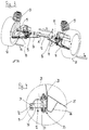
- FIG. 4 shows the attachment of the steering gear 12 to the end wall 25 of the motor vehicle in detail.
- a holder 26 welded to the end wall 25 receives a fastening element 33 (with a rubber element 27 and a fastening screw 28).
- the screw 28 passes through a fastening flange 29 on the housing 30 of the steering gear 12.
- On the side of the housing 30 facing away from the end wall a further flange 31 is provided, to which the pressure strut 14 is fastened by means of a screw 32.
- the rubber element 27 of the fastening element 33 can be made relatively hard, since a displacement path s of approximately +/- 1 mm on the steering gear 12 is sufficient to compensate for the maximum track deviations of approximately +/- 0.5 ° that occur under the influence of lateral forces .
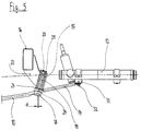
- FIG. 5 shows a portion of the front axle according to the invention.
- the wheel-facing end section of the wishbone 10 is designed as a ball joint 18 with a pin 19 projecting obliquely upwards.
- the pin 19 is inserted into the bushing 15 and its end-side threaded section 20 is fixed in the bushing 15 via a nut 21.
- the bushing 15 is welded to the side member 16 via a bearing block 22.
- the bearing block 22 compensates for the height offset between the link 10 and the side member 16.
- the pressure strut 14 is firmly clamped at its end section remote from the steering gear, which is designed as a disk 23.
- the conical seat 24 of the ball joint 18 ensures a play-free transmission of the transverse movements of the wishbone 10 to the pressure strut 14, which is fastened to the flange 31 of the steering gear 12 via the screw 32.
- the elastic deformation of the longitudinal beam 16 and / or bearing block 22 under the influence of lateral forces causes a displacement s of the cross strut 14 and thus of the steering gear 12.
Abstract
Description
Die Erfindung betrifft eine Vorderachse für ein Kraftfahrzeug nach dem Oberbegriff des Anspruchs 1.The invention relates to a front axle for a motor vehicle according to the preamble of
Insbesondere Kraftfahrzeuge mit Frontantrieb weisen gattungsgemäße Vorderachsen auf, in der Regel mit einem hinter der Radmitte der Vorderräder angeordneten Lenkgetriebe. Ist das Lenkgetriebe starr am Fahrzeugaufbau befestigt, so ergibt sich aufgrund der zwangsläufig vorhandenen Elastizitäten in der Radaufhängung unter der Wirkung einer Seitenkraft eine Vorspurzunahme, was zu einer Übersteuerungstendenz der Vorderachse und zu einem "spitzen Anlenkverhalten" des Kraftfahrzeuges führt. Beide Erscheinungen sind jedoch im Sinne eines neutralen und sicheren Fahrverhalten des Kraftfahrzeuges unerwünscht.In particular, vehicles with front-wheel drive have generic front axles, usually with a steering gear arranged behind the center of the front wheels. If the steering gear is rigidly attached to the vehicle body, there is an increase in toe-in due to the inevitably present elasticities in the wheel suspension under the effect of a lateral force, which leads to an oversteering tendency of the front axle and to a "sharp articulation behavior" of the motor vehicle. However, both phenomena are undesirable in the sense of a neutral and safe driving behavior of the motor vehicle.
Aus diesem Grund werden Lenkgetriebe gattungsgemäßer Vorderachsen häufig elastisch gelagert. Da das Lenkgetriebe über die Spurstangen mit den Lenkern der Radaufhängung verbunden ist, können die aus der Seitenkraft resultierenden elastischen Verschiebungen der Lenker genutzt werden, um über die Spurstangen das Lenkgetriebe mit zu verschieben und damit eine Veränderung des Lenktrapezes zu verhindern. Da gerade bei kleineren und leichteren Fahrzeugen die für die Verschiebung des Lenkgetriebes in Fahrzeugquerrichtung nutzbaren Spurstangendruckkräfte sehr niedrig sind, muß das Lenkgetriebe entsprechend weich gelagert werden, um die gewünschten Verschiebewege zu erreichen. Die weiche Lenkgetriebelagerung führt jedoch auch zu unerwünschten Verschiebungen z. B. in Fahrzeuglängsrichtung und zu einem unpräzisen Lenkgefühl.For this reason, steering gears of generic front axles are often mounted elastically. Since the steering gear is connected to the handlebars of the wheel suspension via the tie rods, the elastic displacements of the handlebars resulting from the lateral force can be used to move the steering gear via the tie rods and thus prevent a change in the trapezoid of the steering. Since the tie rod pressure forces that can be used to shift the steering gear in the transverse direction of the vehicle are very low, especially in smaller and lighter vehicles, the steering gear must be stored in a correspondingly soft manner in order to achieve the desired displacement paths. The soft steering gear bearing however, also leads to undesirable shifts z. B. in the longitudinal direction of the vehicle and to an imprecise steering feel.
Des weiteren ist aus der DE-OS 23 30 229 eine Vorderachse bekannt, bei der die beschriebene Verschiebung des Lenkgetriebes dadurch erreicht wird, daß das Lenkgetriebe an einem Vorderachsträger befestigt ist, der seinerseits elastisch an den Fahrzeugaufbau angebunden ist und über die Lenker unter Seitenkraft verschoben oder verdreht wird. Die oben beschriebene Kompensation des Lenktrapezes wird also durch die mittelbare Verlagerung des Lenkgetriebes zusammen mit dem Vorderachsträger erzielt.Furthermore, from DE-OS 23 30 229 a front axle is known, in which the described displacement of the steering gear is achieved in that the steering gear is attached to a front axle support, which in turn is elastically connected to the vehicle body and displaced via the handlebars under lateral force or is twisted. The compensation of the steering trapezoid described above is thus achieved by the indirect displacement of the steering gear together with the front axle support.
Nachteilig bei der Vorderachse gemäß der DE-OS ist es, daß ein eigener Vorderachsträger erforderlich ist, der kostenintensiv in der Herstellung und Montage ist. Gerade bei Frontantriebsfahrzeugen der unteren Preiskategorien wird eine derartige Achskonstruktion aus Kosten- und Gewichtsgründen in der Regel nicht realisiert.A disadvantage of the front axle according to DE-OS is that a separate front axle support is required, which is expensive to manufacture and assemble. Especially in front-wheel drive vehicles in the lower price categories, such an axle construction is generally not implemented for reasons of cost and weight.
Aufgabe der Erfindung ist es, eine Vorderachse bereitzustellen, bei der mit einfachen Mitteln ein Übersteuern unter Seitenkraft verhindert wird, ohne den Nachteil einer zu weichen Aufhängung des Lenkgetriebes.The object of the invention is to provide a front axle in which oversteer under lateral force is prevented with simple means, without the disadvantage of a too soft suspension of the steering gear.
Diese Aufgabe wird durch die Merkmale des Anspruchs 1 gelöst.
Kerngedanke ist es dabei, das Lenkgetriebe direkt am Fahrzeugaufbau zu befestigen und die Verlagerung des Lenkgetriebes mit eigens hierfür vorgesehenen Druckstreben zu bewirken. Diese Druckstreben greifen direkt an den Lenkern oder im Bereich der Lenker der Radaufhängung an und können damit die Seitenkräfte und die daraus resultierende Verschiebung der Lenker unmittelbar an das Lenkgetriebe weiterleiten. Es ist damit im Unterschied zum Stand der Technik ein eigenes Bauteil vorgesehen, dem die Aufgabe "Verschiebung des Lenkgetriebes" zukommt. Dieses Bauteil kann sehr einfach aufgebaut sein und verursacht dadurch nur geringe Mehrkosten. Die Druckstreben sind vornehmlich in Fahrzeugquerrichtung ausgerichtet, entsprechend der gewünschten Verschieberichtung. In der Regel muß mit den Druckstreben ein geringer Höhen- und/oder Längsversatz zwischen den Lenkern und dem Lenkgetriebe ausgeglichen werden.This object is solved by the features of
The main idea here is to attach the steering gear directly to the vehicle body and to effect the shifting of the steering gear with pressure struts specially provided for this purpose. These struts engage directly on the handlebars or in the area of the handlebars of the wheel suspension and can therefore directly transmit the side forces and the resulting displacement of the handlebars to the steering gear. In contrast to the prior art, a separate component is therefore provided, which has the task of "shifting the steering gear". This component can be constructed in a very simple manner and therefore only causes low additional costs. The pressure struts are primarily aligned in the transverse direction of the vehicle, in accordance with the desired direction of displacement. As a rule, a small height and / or longitudinal offset between the links and the steering gear must be compensated for with the pressure struts.
Erfindungsgemäße Vorderachsen zeichnen sich durch folgende Vorteile gegenüber den bekannten, oben beschriebenen Vorderachsen aus:
Durch den erfindungsgemäßen Einsatz von Druckstreben ist eine um den Faktor fünf bis zehn höhere Krafteinleitung gegenüber der Krafteinleitung über die Spurstangen möglich. Dies hat seinen Grund darin, daß Spurstangen möglichst kraftfrei bleiben sollten, um Rückmeldungen über Fahrbahnunebenheiten an das Lenkrad nach Möglichkeit zu unterdrücken. Außerdem verlaufen Spurstangen bei hintenliegenden Lenkgetrieben nicht in der vertikalen Ebene der Seitenkrafteinleitung, so daß eine direkte Kraftübertragung in einer Ebene nicht möglich ist.
Aufgrund der direkten Krafteinleitung gemäß der Erfindung kann die Lagerung des Lenkgetriebes am Fahrzeugaufbau entsprechend steif ausgebildet werden, wodurch eine hohe Lenkpräzision erreicht wird. Unerwünschte Vorspuränderungen in Richtung einer Übersteuerungstendenz infolge von Seitenkraft aus Kurvenfahrt und einseitiger Brems- oder Antriebskraft werden durch die erfindungsgemäße Vorderachse zuverlässig kompensiert. Durch die elastische Anbindung des Lenkgetriebes an den Fahrzeugaufbau erfolgt zudem eine akustische Entkopplung des Lenkgetriebes, was insbesondere wegen der gängigen Anordnung des Lenkgetriebes im Stirnwandbereich des Kraftfahrzeuges aus akustischen Gründen sehr vorteilhaft ist.
Ein weiterer Vorteil ergibt sich daraus, daß im Gegensatz zu der aufwendigen Lösung der DE-OS die konventionelle Anordnung des Lenkgetriebes im Prinzip erhalten bleibt. Durch den Verzicht auf einen eigenen Vorderachsträger ist die erfindungsgemäße Vorderachse deutlich einfacher im Aufbau und damit billiger in Herstellung und Montage. Gleichzeitig ergeben sich keinerlei Funktionsnachteile. Damit kann die erfindungsgemäße Vorderachse auch bei Fahrzeugen unterer Preiskategorien mit großem Vorteil eingesetzt werden, da sie in ihren positiven Auswirkungen auf das Fahrverhalten des Kraftfahrzeugs der aus der DE-OS bekannten aufwendigen Lösung gleichwertig ist.Front axles according to the invention are distinguished by the following advantages over the known front axles described above:
The use of pressure struts according to the invention enables a force introduction that is five to ten times higher than the force introduction via the tie rods. The reason for this is that tie rods should remain as free of force as possible in order to suppress feedback on uneven road surfaces to the steering wheel if possible. In addition, tie rods in rear steering gears do not run in the vertical plane of the introduction of lateral force, so that direct power transmission in one plane is not possible.
Due to the direct introduction of force according to the invention, the bearing of the steering gear on the vehicle body can be made correspondingly rigid, whereby a high steering precision is achieved. Unwanted toe-in changes in the direction of an oversteer tendency due to lateral force from cornering and one-sided braking or driving force are reliably compensated for by the front axle according to the invention. Due to the elastic connection of the steering gear to the vehicle body, there is also an acoustic decoupling of the steering gear, which is particularly advantageous for acoustic reasons because of the common arrangement of the steering gear in the end wall area of the motor vehicle.
Another advantage results from the fact that, in contrast to the complex solution of DE-OS, the conventional arrangement of the steering gear is in principle retained. By dispensing with a separate front axle support, the front axle according to the invention is significantly simpler in construction and therefore cheaper to manufacture and assemble. At the same time, there are no functional disadvantages. The front axle according to the invention can thus also be used with great advantage in vehicles of lower price categories, since its positive effects on the driving behavior of the motor vehicle are equivalent to the complex solution known from DE-OS.
Kraftfahrzeuge mit einer in Fahrzeugquerrichtung bauartbedingten relativ elastischen Querlenker-Anbindung eignen sich in besonderer Weise für den Einsatz der erfindungsgemäßen Vorderachse. Fahrzeug-Längsträger nach Anspruch 2, wie z. B. die Motorlängsträger sind in begrenztem Maß querelastisch, bedingt durch den bei Frontantriebsfahrzeugen in der Regel vorhandenen Höhenversatz zwischen der Krafteinleitungsstelle und dem hohen Motorträgerverlauf. Mit der Anbindung der Druckstrebe an den Fahrzeuglängsträger im Bereich der Lenkeranbindung wird der ansonsten nachteilige Effekt der elastischen Verformung des Längsträgers genutzt, um damit gleichzeitig auch die Druckstrebe in Fahrzeugquerrichtung zu verschieben und eine Kompensation der Verformung des Lenktrapezes zu erreichen.Motor vehicles with a relatively elastic wishbone connection in the transverse direction of the vehicle are particularly suitable for the use of the front axle according to the invention. Vehicle side member according to
Anspruch 3 sieht die Anbindung von Lenker und Druckstrebe am Fahrzeugaufbau über ein gemeinsames Zwischenglied vor, das gemäß Anspruch 4 als Lagerbock mit einer Buchse ausgebildet ist. Bei steifen Längsträgern sind gemäß Anspruch 5 elastische Mittel wie beispielsweise eine Buchse aus gummielastischem Material vorgesehen, um unter Seitenkrafteinfluß eine ausreichende Verschiebung der Druckstrebe in Fahrzeugquerrichtung zu erreichen.
Die Druckstrebe ist in der Regel unmittelbar an den Endabschnitt des Lenkers angebunden. Abweichend hiervon ist ebenso möglich, die Druckstrebe in unmittelbarer Nähe der Lenkerlagerung z. B. direkt an den Längsträger des Fahrzeugaufbaus anzubinden.The strut is usually connected directly to the end section of the handlebar. Deviating from this is also possible, the pressure strut in the immediate vicinity of the handlebar mounting z. B. connect directly to the side member of the vehicle body.
Die erfindungsgemäße Vorderachse ist gleichermaßen für Fahrzeuge mit Front- oder Heckantrieb einsetzbar. Da heckangetriebene Personenkraftwagen tendenziell ein übersteuerndes Fahrverhalten zeigen, wirkt sich hier die Erfindung besonders vorteilhaft aus.The front axle according to the invention can equally be used for vehicles with front or rear drive. Since rear-driven passenger cars tend to have oversteering driving behavior, the invention has a particularly advantageous effect here.
Die Erfindung und weitere Einzelheiten sind im folgenden anhand von Prinzipdarstellungen und möglicher Ausführungsbeispiele näher erläutert. Es zeigt:
Figur 1- eine schematische Darstellung einer Vorderachse nach dem Stand der Technik in der Draufsicht,
Figur 2- eine entsprechende Darstellung einer erfindungsgemäßen Vorderachse,
Figur 3- eine perspektivische Darstellung eines Ausführungsbeispiels einer erfindungsgemäßen Vorderachse,
Figur 4- eine in
Figur 3 mit A bezeichnete Einzelheit in vergrößerter Schnittdarstellung und Figur 5- die Anbindung der rechten Druckstrebe in einer gegenüber
Figur 3 vergrößerten Darstellung in der Ansicht von vorne.
- Figure 1
- 1 shows a schematic illustration of a front axle according to the prior art in plan view,
- Figure 2
- a corresponding representation of a front axle according to the invention,
- Figure 3
- 2 shows a perspective illustration of an exemplary embodiment of a front axle according to the invention,
- Figure 4
- a detail denoted by A in Figure 3 in an enlarged sectional view and
- Figure 5
- the connection of the right pressure strut in an enlarged view compared to Figure 3 in the view from the front.
Figur 1 zeigt den schematischen Aufbau einer bekannten Vorderachse, deren Vorderräder 1 über Dreieckslenker 2 am Fahrzeugaufbau geführt sind. Die Lenkung der Vorderräder 1 erfolgt über ein hinter der Radmitte liegendes Lenkgetriebe 3 sowie über Spurstangen 4 und Spurhebel 5.Figure 1 shows the schematic structure of a known front axle, the
Bei Kurvenfahrt nach rechts entsteht am kurvenäußeren Vorderrad 1 eine Seitenkraft Sa, die eine geringfügige Verschiebung des kurvenäußeren Dreiecklenkers 2 zur mit der Bezugszahl 6 bezeichneten Fahrzeugmitte bewirkt. Da das Lenkgetriebe 3 über die Befestigung 7a starr an den Fahrzeugaufbau angebunden ist, ergibt sich am kurvenäußeren Rad eine Verschiebung des Lenktrapezes um den Betrag sa. Hieraus resultiert die in Figur 1 strichpunktiert dargestellte Stellung des Vorderrades 1 unter einem Spurwinkel µa, das heißt, es ergibt sich eine deutliche Vorspurzunahme am kurvenäußeren Vorderrad 1. Gleichzeitig bewirkt die Seitenkraft Si am kurveninneren Vorderrad 1 eine Verschiebung um den Weg si sowie eine leichte Vorspurabnahme um den Winkel µi. Insgesamt ergibt sich bei Vorderachse gemäß Figur 1 eine deutliche Übersteuertendenz und ein "spitzes Anlenken".When cornering to the right, a lateral force S a arises on the
Wird bei der bekannten Vorderachse das Lenkgetriebe elastisch gelagert (in Figur 1 nicht ausgeführt), so kann das Lenkgetriebe 5 unter der Wirkung der Seitenkräfte Sa,i, die über die Spurhebel 5 und die Spurstangen 4 eingeleitet werden, so verschoben werden, daß die Übersteuerungstendenz kompensiert werden kann. Wegen des ungünstigen Krafteinleitungsangriffes sind jedoch die Lenkgetriebelager zur Ausnutzung dieses Effektes sehr weich auszuführen, was Nachteile hinsichtlich des Lenkverhaltens mit sich bringt.If the steering gear is mounted elastically in the known front axle (not shown in FIG. 1), the
Die in Figur 2 dargestellte Vorderachse weist gegenüber der Vorderachse aus Figur 1 eine elastische Lagerung 7b des Lenkgetriebes 1 sowie zusätzliche Druckstreben 8 auf. Die Druckstreben 8 leiten die über die Vorderräder 1 und die Lenker 2 eingeleitete Seitenkraft an das Lenkgetriebe 3 weiter, das hierdurch um den Weg sa verschoben wird. Hierdurch ergibt sich letztendlich keine Vorspuränderung am kurvenäußeren Rad 1, sondern lediglich eine Parallelverschiebung (strichliert dargestellt). Am kurveninneren Rad ergibt sich zugleich eine deutliche Vorspurabnahme um den Winkel µi, wodurch das Fahrverhalten insgesamt deutlich in Richtung untersteuernd beeinflußt wird.Compared to the front axle from FIG. 1, the front axle shown in FIG. 2 has an
Die Erfindung kann in analoger Weise auch bei Fahrzeugen mit vor der Radmitte liegender Lenkung angewandt werden. Aufgrund der umgekehrten Verhältnisse ist für diesen Fall jedoch zusätzlich ein Mechanismus, beispielsweise in Form eines Umlenkhebels, vorzusehen, um durch eine Verschiebung des Lenkgetriebes eine Vorspurkompensation zu erreichen.The invention can also be applied in an analogous manner to vehicles with steering located in front of the wheel center. Due to the reverse situation, a mechanism, for example in the form of a bell crank, must also be provided in this case in order to achieve toe-in compensation by shifting the steering gear.
Figur 3 zeigt ein mögliches Ausführungsbeispiel einer erfindungsgemäßen Vorderachse in der Ansicht entgegen der Fahrtrichtung FR. Die Vorderachse weist unter anderem Dreieckslenker 10, Spurstangen 11, ein Lenkgetriebe 12, Federbeine 13 sowie Druckstreben 14 auf. Die Dreieckslenker 10 und mit ihnen auch die Druckstreben 14 sind über Buchsen 15 an den Motorlängsträgern 16 angeordnet. Die an den Vorderrädern 17 angreifenden Seitenkräfte Sa und Si bewirken die oben beschriebene Verschiebung des Lenkgetriebes 12 um den Weg s in Fahrzeugquerrichtung.Figure 3 shows a possible embodiment of a front axle according to the invention in the view against the direction of travel FR. The front axle has, among other things,
Figur 4 zeigt die Befestigung des Lenkgetriebes 12 an der Stirnwand 25 des Kraftfahrzeuges im Detail. Ein an die Stirnwand 25 angeschweißter Halter 26 nimmt ein Befestigungselement 33 (mit einem Gummielement 27 und einer Befestigungsschraube 28) auf. Die Schraube 28 durchsetzt einen Befestigungsflansch 29 am Gehäuse 30 des Lenkgetriebes 12. Auf der stirnwandabgewandten Seite des Gehäuses 30 ist ein weiterer Flansch 31 vorgesehen, an dem über eine Schraube 32 die Druckstrebe 14 befestigt ist.
Das Gummielement 27 des Befestigungselements 33 kann relativ hart ausgeführt sein, da am Lenkgetriebe 12 bereits ein Verschiebeweg s von ca. +/- 1 mm ausreicht, um die maximalen, unter Seitenkrafteinfluß auftretenden Spurabweichungen von ca. +/-0,5° zu kompensieren.Figure 4 shows the attachment of the
The
Figur 5 zeigt einen Teilabschnitt der erfindungsgemäßen Vorderachse. Der radabgewandte Endabschnitt des Dreieckslenkers 10 ist als Kugelgelenk 18 ausgebildet, mit einem schräg aufwärts abstehenden Zapfen 19. Der Zapfen 19 ist in die Buchse 15 eingesetzt und mit seinem endseitigen Gewindeabschnitt 20 über eine Mutter 21 in der Buchse 15 fixiert. Die Buchse 15 ist über einen Lagerbock 22 am Längsträger 16 angeschweißt. Der Lagerbock 22 gleicht den Höhenversatz zwischen dem Lenker 10 und dem Längsträger 16 aus. Zwischen dem Kugelgelenk 18 und der unteren Stirnfläche der Buchse 15 ist die Druckstrebe 14 an ihrem lenkgetriebeabgewandten Endabschnitt, der als Scheibe 23 ausgebildet ist, fest eingespannt. Der Kegelsitz 24 des Kugelgelenks 18 sorgt für eine spielfreie Übertragung der Querbewegungen des Dreieckslenkers 10 auf die Druckstrebe 14, die über die Schraube 32 am Flansch 31 des Lenkgetriebes 12 befestigt ist. Somit bewirkt die elastische Verformung von Längsträger 16 und/oder Lagerbock 22 unter Seitenkrafteinfluß eine Verschiebung s der Querstrebe 14 und damit des Lenkgetriebes 12.Figure 5 shows a portion of the front axle according to the invention. The wheel-facing end section of the
Claims (5)
dadurch gekennzeichnet, daß der radabgewandte Endabschnitt des Lenkers (2, 10) an einem Längsträger (16) des Fahrzeugaufbaus angelenkt ist.Front axle according to claim 1,
characterized in that the end portion of the handlebar (2, 10) facing away from the wheel is articulated on a longitudinal member (16) of the vehicle body.
dadurch gekennzeichnet, daß sowohl der radabgewandte Endabschnitt des Lenkers (10) als auch der lenkgetriebeabgewandte Endabschnitt der Druckstrebe (14) an einem am Fahrzeugaufbau (16) angeordneten Zwischenglied (19) angreifen.Front axle according to claim 1 and / or 2,
characterized in that both the end portion of the handlebar (10) facing away from the wheel and the end portion of the pressure strut (14) facing away from the steering gear engage an intermediate member (19) arranged on the vehicle body (16).
dadurch gekennzeichnet, daß das Zwischenglied (19) als ein am Längsträger (16) angeordneter Lagerbock (22) mit einer Lagerbuchse (15) ausgebildet ist.Front axle according to claim 3,
characterized in that the intermediate member (19) is designed as a bearing block (22) arranged on the longitudinal member (16) with a bearing bush (15).
dadurch gekennzeichnet, daß eine Lagerbuchse mit gummielastischem Material vorgesehen ist.Front axle according to claim 3 and / or 4,
characterized in that a bearing bush is provided with rubber-elastic material.
Applications Claiming Priority (2)
| Application Number | Priority Date | Filing Date | Title |
|---|---|---|---|
| DE19528431A DE19528431A1 (en) | 1995-08-02 | 1995-08-02 | Front axle for a motor vehicle |
| DE19528431 | 1995-08-02 |
Publications (2)
| Publication Number | Publication Date |
|---|---|
| EP0756981A1 true EP0756981A1 (en) | 1997-02-05 |
| EP0756981B1 EP0756981B1 (en) | 2001-10-24 |
Family
ID=7768538
Family Applications (1)
| Application Number | Title | Priority Date | Filing Date |
|---|---|---|---|
| EP96102819A Expired - Lifetime EP0756981B1 (en) | 1995-08-02 | 1996-02-26 | Front axle for a motor vehicle |
Country Status (3)
| Country | Link |
|---|---|
| EP (1) | EP0756981B1 (en) |
| DE (2) | DE19528431A1 (en) |
| ES (1) | ES2164175T3 (en) |
Cited By (2)
| Publication number | Priority date | Publication date | Assignee | Title |
|---|---|---|---|---|
| EP1270374A3 (en) * | 2001-06-29 | 2004-03-24 | Sistemi Sospensioni S.p.A. | A cross-member for a motor-vehicle suspension system |
| WO2004058558A1 (en) * | 2002-12-23 | 2004-07-15 | Dana Corporation | Single-piece steering gear fixation-bracket and steering gear joint-member |
Families Citing this family (3)
| Publication number | Priority date | Publication date | Assignee | Title |
|---|---|---|---|---|
| DE19751450A1 (en) * | 1997-11-20 | 1999-05-27 | Zahnradfabrik Friedrichshafen | Axle system for motor vehicles |
| DE10221697B4 (en) * | 2002-05-16 | 2011-05-05 | Dr. Ing. H.C. F. Porsche Aktiengesellschaft | Steerable axle for a motor vehicle |
| DE102019109499A1 (en) * | 2019-04-10 | 2020-10-15 | Bayerische Motoren Werke Aktiengesellschaft | Vehicle axle with a steering gear and understeering driving behavior |
Citations (2)
| Publication number | Priority date | Publication date | Assignee | Title |
|---|---|---|---|---|
| EP0143558A2 (en) * | 1983-11-02 | 1985-06-05 | Bl Technology Limited | Steering and suspension system |
| JPS6150808A (en) * | 1984-08-20 | 1986-03-13 | Daihatsu Motor Co Ltd | Front body construction of automobile |
Family Cites Families (2)
| Publication number | Priority date | Publication date | Assignee | Title |
|---|---|---|---|---|
| DE2330229C2 (en) * | 1973-06-14 | 1982-09-02 | Volkswagenwerk Ag, 3180 Wolfsburg | Front axle for motor vehicles |
| DE4414020C1 (en) * | 1994-04-22 | 1995-06-08 | Daimler Benz Ag | Elastic mounting for rack-and-pinion automotive steering gear |
-
1995
- 1995-08-02 DE DE19528431A patent/DE19528431A1/en not_active Withdrawn
-
1996
- 1996-02-26 EP EP96102819A patent/EP0756981B1/en not_active Expired - Lifetime
- 1996-02-26 ES ES96102819T patent/ES2164175T3/en not_active Expired - Lifetime
- 1996-02-26 DE DE59607983T patent/DE59607983D1/en not_active Expired - Lifetime
Patent Citations (2)
| Publication number | Priority date | Publication date | Assignee | Title |
|---|---|---|---|---|
| EP0143558A2 (en) * | 1983-11-02 | 1985-06-05 | Bl Technology Limited | Steering and suspension system |
| JPS6150808A (en) * | 1984-08-20 | 1986-03-13 | Daihatsu Motor Co Ltd | Front body construction of automobile |
Non-Patent Citations (1)
| Title |
|---|
| PATENT ABSTRACTS OF JAPAN vol. 010, no. 211 (M - 501) 24 July 1986 (1986-07-24) * |
Cited By (3)
| Publication number | Priority date | Publication date | Assignee | Title |
|---|---|---|---|---|
| EP1270374A3 (en) * | 2001-06-29 | 2004-03-24 | Sistemi Sospensioni S.p.A. | A cross-member for a motor-vehicle suspension system |
| WO2004058558A1 (en) * | 2002-12-23 | 2004-07-15 | Dana Corporation | Single-piece steering gear fixation-bracket and steering gear joint-member |
| US6880842B2 (en) | 2002-12-23 | 2005-04-19 | Torque-Traction Technologies, Inc. | Single-piece steering gear bracket and steering gear joint member |
Also Published As
| Publication number | Publication date |
|---|---|
| ES2164175T3 (en) | 2002-02-16 |
| DE19528431A1 (en) | 1997-02-06 |
| EP0756981B1 (en) | 2001-10-24 |
| DE59607983D1 (en) | 2001-11-29 |
Similar Documents
| Publication | Publication Date | Title |
|---|---|---|
| DE19521875C2 (en) | Axle suspension for rigid axles in vehicles | |
| DE3714688C2 (en) | ||
| WO2007118629A1 (en) | Steering knuckle for a vehicle | |
| EP1057665A1 (en) | Axle suspension for rigid axles in vehicles | |
| EP1882600B1 (en) | Twist beam axle | |
| WO2007087793A1 (en) | Driven vehicle axle comprising an independent wheel suspension | |
| EP3452310B1 (en) | Single-wheel suspension arrangement of a vehicle having a wheel-controlling leaf spring element composed of a fiber composite material | |
| DE3809995C2 (en) | ||
| DE102014205990B4 (en) | Articulated connection for transmitting a steering movement to a wheel of a vehicle and steering lever | |
| DE19717069A1 (en) | Independent wheel suspension for motor vehicles, in particular passenger cars | |
| WO2020038855A1 (en) | Rear axle of a vehicle | |
| DE102009032644A1 (en) | Semi-rigid axle i.e. twist-beam rear axle, for multi-lane motor vehicle, has wheel carriers mounted at semi-trailing arms around drag axis, and steering wheels are connected on actuator for rotating carriers around axis | |
| DE102016207631A1 (en) | Independent suspension of a vehicle with a wheel-guiding leaf spring element made of a fiber composite material | |
| EP3649038A1 (en) | Adjusting device for a chassis of a motor vehicle and rear-axle steering system | |
| EP0756981B1 (en) | Front axle for a motor vehicle | |
| DE3912520B4 (en) | Rear axle for a motor vehicle | |
| DE3242930A1 (en) | Wheel suspension for motor vehicles | |
| EP0800937B1 (en) | Axle fixation | |
| DE3133312A1 (en) | Body-side bearing support of a motor vehicle | |
| DE3918359A1 (en) | Vehicle wheel suspension - has upper and lower link arms connected by coupling that forces wheel-side joints of arms to move in same direction | |
| DE4008465A1 (en) | Preloaded automotive suspension bearing - has recesses in elastomer body opposite each other in transverse direction | |
| EP0812712B1 (en) | Subframe for connecting the wheel guiding elements of a vehicle with its body | |
| WO2017137186A1 (en) | Steerable twist-beam rear suspension | |
| DE102017201747B3 (en) | Independent suspension of a vehicle | |
| DE19721754B4 (en) | Independent suspension for motor vehicles, in particular passenger cars |
Legal Events
| Date | Code | Title | Description |
|---|---|---|---|
| PUAI | Public reference made under article 153(3) epc to a published international application that has entered the european phase |
Free format text: ORIGINAL CODE: 0009012 |
|
| AK | Designated contracting states |
Kind code of ref document: A1 Designated state(s): DE ES FR GB IT |
|
| 17P | Request for examination filed |
Effective date: 19970730 |
|
| 17Q | First examination report despatched |
Effective date: 19990430 |
|
| GRAG | Despatch of communication of intention to grant |
Free format text: ORIGINAL CODE: EPIDOS AGRA |
|
| GRAG | Despatch of communication of intention to grant |
Free format text: ORIGINAL CODE: EPIDOS AGRA |
|
| GRAH | Despatch of communication of intention to grant a patent |
Free format text: ORIGINAL CODE: EPIDOS IGRA |
|
| GRAH | Despatch of communication of intention to grant a patent |
Free format text: ORIGINAL CODE: EPIDOS IGRA |
|
| GRAA | (expected) grant |
Free format text: ORIGINAL CODE: 0009210 |
|
| AK | Designated contracting states |
Kind code of ref document: B1 Designated state(s): DE ES FR GB IT |
|
| REF | Corresponds to: |
Ref document number: 59607983 Country of ref document: DE Date of ref document: 20011129 |
|
| REG | Reference to a national code |
Ref country code: GB Ref legal event code: IF02 |
|
| ET | Fr: translation filed | ||
| GBT | Gb: translation of ep patent filed (gb section 77(6)(a)/1977) |
Effective date: 20020105 |
|
| REG | Reference to a national code |
Ref country code: ES Ref legal event code: FG2A Ref document number: 2164175 Country of ref document: ES Kind code of ref document: T3 |
|
| PLBE | No opposition filed within time limit |
Free format text: ORIGINAL CODE: 0009261 |
|
| STAA | Information on the status of an ep patent application or granted ep patent |
Free format text: STATUS: NO OPPOSITION FILED WITHIN TIME LIMIT |
|
| 26N | No opposition filed | ||
| PGFP | Annual fee paid to national office [announced via postgrant information from national office to epo] |
Ref country code: DE Payment date: 20120322 Year of fee payment: 17 |
|
| PGFP | Annual fee paid to national office [announced via postgrant information from national office to epo] |
Ref country code: IT Payment date: 20120223 Year of fee payment: 17 |
|
| PGFP | Annual fee paid to national office [announced via postgrant information from national office to epo] |
Ref country code: ES Payment date: 20130131 Year of fee payment: 18 Ref country code: FR Payment date: 20130319 Year of fee payment: 18 Ref country code: GB Payment date: 20130227 Year of fee payment: 18 |
|
| REG | Reference to a national code |
Ref country code: DE Ref legal event code: R119 Ref document number: 59607983 Country of ref document: DE Effective date: 20130903 |
|
| PG25 | Lapsed in a contracting state [announced via postgrant information from national office to epo] |
Ref country code: DE Free format text: LAPSE BECAUSE OF NON-PAYMENT OF DUE FEES Effective date: 20130903 |
|
| GBPC | Gb: european patent ceased through non-payment of renewal fee |
Effective date: 20140226 |
|
| REG | Reference to a national code |
Ref country code: FR Ref legal event code: ST Effective date: 20141031 |
|
| PG25 | Lapsed in a contracting state [announced via postgrant information from national office to epo] |
Ref country code: FR Free format text: LAPSE BECAUSE OF NON-PAYMENT OF DUE FEES Effective date: 20140228 Ref country code: GB Free format text: LAPSE BECAUSE OF NON-PAYMENT OF DUE FEES Effective date: 20140226 |
|
| REG | Reference to a national code |
Ref country code: ES Ref legal event code: FD2A Effective date: 20150401 |
|
| PG25 | Lapsed in a contracting state [announced via postgrant information from national office to epo] |
Ref country code: ES Free format text: LAPSE BECAUSE OF NON-PAYMENT OF DUE FEES Effective date: 20140227 |
|
| PG25 | Lapsed in a contracting state [announced via postgrant information from national office to epo] |
Ref country code: IT Free format text: LAPSE BECAUSE OF NON-PAYMENT OF DUE FEES Effective date: 20140226 |