EP0755795A2 - Vorrichtung zum Einfüllen von Flüssigkeit in einen Behälter - Google Patents
Vorrichtung zum Einfüllen von Flüssigkeit in einen Behälter Download PDFInfo
- Publication number
- EP0755795A2 EP0755795A2 EP96810248A EP96810248A EP0755795A2 EP 0755795 A2 EP0755795 A2 EP 0755795A2 EP 96810248 A EP96810248 A EP 96810248A EP 96810248 A EP96810248 A EP 96810248A EP 0755795 A2 EP0755795 A2 EP 0755795A2
- Authority
- EP
- European Patent Office
- Prior art keywords
- container
- cylinder
- ink
- liquid
- piston
- Prior art date
- Legal status (The legal status is an assumption and is not a legal conclusion. Google has not performed a legal analysis and makes no representation as to the accuracy of the status listed.)
- Granted
Links
Images
Classifications
-
- B—PERFORMING OPERATIONS; TRANSPORTING
- B41—PRINTING; LINING MACHINES; TYPEWRITERS; STAMPS
- B41J—TYPEWRITERS; SELECTIVE PRINTING MECHANISMS, i.e. MECHANISMS PRINTING OTHERWISE THAN FROM A FORME; CORRECTION OF TYPOGRAPHICAL ERRORS
- B41J2/00—Typewriters or selective printing mechanisms characterised by the printing or marking process for which they are designed
- B41J2/005—Typewriters or selective printing mechanisms characterised by the printing or marking process for which they are designed characterised by bringing liquid or particles selectively into contact with a printing material
- B41J2/01—Ink jet
- B41J2/17—Ink jet characterised by ink handling
- B41J2/175—Ink supply systems ; Circuit parts therefor
- B41J2/17503—Ink cartridges
- B41J2/17506—Refilling of the cartridge
Definitions
- a device for refilling ink into a print head of an ink jet printer comprises two cylinders arranged side by side. One contains ink, the other a piston and acts as a suction pump when it is filled. Hollow needles protrude from the cylinders and are inserted into the printhead container. The tips of the hollow needles are protected by pins which are pulled off before use.
- the present invention has for its object to improve this device. This object is achieved by the combination of features of the claims.
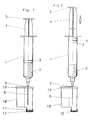
- the device according to Figures 1 and 2 comprises a cylinder 1 which is only a fraction, i.e. is less than half full of Ink 2.
- a piston 3 with a piston rod 4 which has a grip head 5 at the free end, is located directly above the ink 2.
- a hollow needle 6 with a sealing ring 7 is attached to the cylinder 1 at the lower end.
- the nozzle openings 11 are first sealed airtight with a sealing cap 12.
- the hollow needle 6 is inserted until the sealing ring 7 is in sealing contact with the lid 13.
- the piston 3 is then raised to the position shown in FIG. 2.
- Part of the air in the printhead 10 is sucked through the ink.
- the grip head 5 is released, the ink 2 is now sucked into the print head 10 by the negative pressure prevailing therein.
- the cylinder 1 can have an air supply opening 8 adjacent to its upper end. Through this air flows in as soon as the piston 3 has reached its upper end position shown in FIG. 2.
- the device described is considerably simpler than that according to the above-mentioned DE-GM 295 02 908 and only requires a single opening in the lid 13 of the print head 10, which is usually present anyway. It has been shown that by sucking the ink into the foam body 32 under vacuum, the latter can be filled considerably more efficiently and a decrease in the filling capacity after several fillings can be avoided. This is attributed to the fact that the vacuum is sucked out of the air in the air-filled pores of the foam body 32.
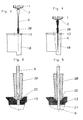
- FIGS. 3 to 6 differs mainly from that according to FIGS. 1 and 2 in that, in the delivery state, a pin 20 is plugged onto the free end of the hollow needle 6 and is pierced through the cover 13 of the print head 10 when the hollow needle 6 is inserted .
- the pin 20 is centered in a conical countersink 22 arranged coaxially with the opening 21 in the cover 13. This configuration ensures that the pin 20 does not have to be removed before the needle 6 is inserted! In the event of overpressure of the ink 2 in the cylinder 1, no ink can thus spray from the needle 6 into the surroundings.
- This embodiment is also suitable for filling the printhead with pressure, so that the piston 3 is not first pulled up, but is pressed down. This requires that the printhead is not airtight.
- the pin 20 also serves as a stop when the needle 6 is inserted so that it penetrates to the optimum height within the print head 10.
- the device described is also suitable for filling other containers with liquid, e.g. in the medical field.
Landscapes
- Basic Packing Technique (AREA)
- Filling Of Jars Or Cans And Processes For Cleaning And Sealing Jars (AREA)
- Ink Jet (AREA)
Abstract
Description
- Aus dem DE-GM 295 02 908 ist eine Vorrichtung zum Nachfüllen von Tinte in einen Druckkopf eines Ink-Jet-Printers bekannt. Sie umfasst zwei nebeneinander angeordnete Zylinder. Der eine enthält Tinte, der andere einen Kolben und wirkt beim Befüllen als Saugpumpe. Von den Zylindern stehen Hohlnadeln ab, die in den Behälter des Druckkopfs eingesteckt werden. Die Spitzen der Hohlnadeln sind durch Zapfen geschützt, welche vor dem Gebrauch abgezogen werden.
- Der vorliegenden Erfindung liegt die Aufgabe zugrunde, diese Vorrichtung zu verbessern. Diese Aufgabe wird durch die Merkmalskombination der Ansprüche gelöst.
- Nachfolgend wird ein Ausführungsbeispiel der Erfindung anhand der Zeichnungen erläutert. Darin zeigt:
- Figuren 1 und 2 eine erste Ausführungsform, und
- Figuren 3 bis 6 eine zweite Ausführungsform.
- Die Vorrichtung nach Figuren 1 und 2 umfasst einen Zylinder 1, der nur zu einem Bruchteil, d.h. zu weniger als der Hälfte mit Tinte 2 gefüllt ist. Im Ausgangszustand (Figur 1) befindet sich unmittelbar oberhalb der Tinte 2 ein Kolben 3 mit einer Kolbenstange 4, die am freien Ende einen Griffkopf 5 aufweist. Am unteren Ende ist am Zylinder 1 eine Hohlnadel 6 angebracht mit einem Dichtring 7.
- Zum Nachfüllen des Druckkopfs 10 werden zunächst dessen Düsenöffnungen 11 mit einer Dichtkappe 12 luftdicht verschlossen. Durch eine Oeffnung im Deckel 13 des Druckkopfs 10 wird die Hohlnadel 6 bis zur abdichtenden Anlage des Dichtrings 7 am Deckel 13 eingesteckt. Anschliessend wird der Kolben 3 in die Position nach Figur 2 hochgezogen. Dabei wird ein Teil der Luft im Druckkopf 10 durch die Tinte hindurch abgesaugt. Beim Loslassen des Griffkopfs 5 wird nun die Tinte 2 in den Druckkopf 10 durch den darin herrschenden Unterdruck eingesaugt. Um das Einfliessen der Tinte 2 zu erleichtern kann der Zylinder 1 benachbart seinem oberen Ende eine Luftzufuhröffnung 8 haben. Durch diese strömt Luft ein, sobald der Kolben 3 seine in Fig. 2 dargestellte obere Endstellung erreicht hat.
- Die beschriebene Vorrichtung ist erheblich einfacher als jene gemäss dem eingangs erwähnten DE-GM 295 02 908 und erfordert bloss eine einzige Oeffnung im Deckel 13 des Druckkopfs 10, welche üblicherweise ohnehin vorhanden ist. Es hat sich gezeigt, dass durch das Einsaugen der Tinte unter Vakuum in den Schaumkörper 32 dieser erheblich effizienter gefüllt und ein Absinken der Füllkapazität nach mehreren Füllungen vermieden werden kann. Dies wird darauf zurückgeführt, dass durch den Unterdruck die Luft in den luftgefüllten Poren des Schaumkörpers 32 abgesaugt wird.
- Die Ausführungsform nach Figuren 3 bis 6 unterscheidet sich hauptsächlich dadurch von jener nach Figuren 1 und 2, dass im Lieferzustand auf das freie Ende der Hohlnadel 6 ein Zapfen 20 aufgesteckt ist, welcher beim Einstecken der Hohlnadel 6 durch den Deckel 13 des Druckkopfs 10 durchstochen wird. Der Zapfen 20 wird in einer koaxial zur Oeffnung 21 im Deckel 13 angeordneten konischen Ansenkung 22 zentriert. Durch diese Ausbildung wird erreicht, dass der Zapfen 20 vor dem Einstecken der Nadel 6 nicht entfernt werden muss! Damit kann bei einem allfälligen Ueberdruck der Tinte 2 im Zylinder 1 keine Tinte aus der Nadel 6 in die Umgebung spritzen.
- Diese Ausführungsform eignet sich auch zum Befüllen des Druckkopfs mit Druck, wo also der Kolben 3 nicht zuerst hochgezogen, sondern hinunter gedrückt wird. Dies setzt voraus, dass der Druckkopf nicht luftdicht ist. Der Zapfen 20 dient gleichzeitig als Anschlag beim Einstecken der Nadel 6, damit diese auf die optimale Höhe innerhalb des Druckkopfs 10 eindringt.
- Die beschriebene Vorrichtung eignet sich auch zum Befüllen anderer Behälter mit Flüssigkeit, z.B. im Medizinalbereich.
Claims (5)
- Vorrichtung zum Einfüllen einer Flüssigkeit in einen Behälter (10), insbesondere von Tinte in einen Druckkopf eines Ink-Jet-Printers, umfassend einen die Flüssigkeit (2) enthaltenden Zylinder (1), von welchem eine Hohlnadel (6) absteht, gekennzeichnet durch ein Abdichtelement (7,20), das bei in den Behälter (10) eingesteckter Hohlnadel (6) gegen eine Behälterwand (13) abdichtet.
- Vorrichtung nach Anspruch 1, wobei das Abdichtelement durch einen Zapfen (20) gebildet ist, der im Lieferzustand auf die Hohlnadel abdichtend aufgesteckt ist und beim Eindringen der Hohlnadel (6) in den Behälter (10) von dieser durchstochen wird.
- Vorrichtung nach Anspruch 1 oder 2, wobei der Zylinder (1) oberhalb der Flüssigkeit (2) einen Kolben (3) mit Kolbenstange (4) enthält, welche am freien Ende einen Griff (5) aufweist.
- Vorrichtung nach Anspruch 3, wobei die Flüssigkeit (2) nur einen Bruchteil des Zylinders (1) füllt, so dass der Kolben (3) beim Befüllen des Behälters (10) zunächst gezogen werden kann, um Luft aus dem Behälter (10) durch die Flüssigkeit hindurch abzusaugen.
- Vorrichtung nach Anspruch 4, wobei der Zylinder (1) benachbart seinem der Hohlnadel (6) gegenüberliegenden Ende eine Luftzufuhröffnung (8) aufweist.
Applications Claiming Priority (2)
| Application Number | Priority Date | Filing Date | Title |
|---|---|---|---|
| DE29512003U | 1995-07-25 | ||
| DE29512003U DE29512003U1 (de) | 1995-07-25 | 1995-07-25 | Vorrichtung zum Einfüllen von Flüssigkeit in einen Behälter |
Publications (3)
| Publication Number | Publication Date |
|---|---|
| EP0755795A2 true EP0755795A2 (de) | 1997-01-29 |
| EP0755795A3 EP0755795A3 (de) | 1997-07-30 |
| EP0755795B1 EP0755795B1 (de) | 2006-07-26 |
Family
ID=8010973
Family Applications (1)
| Application Number | Title | Priority Date | Filing Date |
|---|---|---|---|
| EP96810248A Expired - Lifetime EP0755795B1 (de) | 1995-07-25 | 1996-04-19 | Vorrichtung und Verfahren zum Einfüllen von Flüssigkeit in einen Behälter |
Country Status (4)
| Country | Link |
|---|---|
| US (1) | US5883652A (de) |
| EP (1) | EP0755795B1 (de) |
| AT (1) | ATE333999T1 (de) |
| DE (2) | DE29512003U1 (de) |
Cited By (4)
| Publication number | Priority date | Publication date | Assignee | Title |
|---|---|---|---|---|
| EP0872349A3 (de) * | 1997-04-14 | 1998-11-18 | Pelikan Produktions Ag | Tintennachfüllvorrichtung eines Behälters in einer Druckkassette |
| EP0853001A3 (de) * | 1997-01-08 | 1999-04-21 | Brother Kogyo Kabushiki Kaisha | Farbstoffpatrone, Herstellungsverfahren und Farbzufuhr |
| EP0878309A3 (de) * | 1997-05-12 | 1999-04-28 | Hana Company Limited | Nachfüllanordnung für eine Tintenstrahldruckpatrone |
| CN111422808A (zh) * | 2020-03-19 | 2020-07-17 | 安徽恒达药业有限公司 | 一种颠茄流浸膏生产用快速灌装设备 |
Families Citing this family (10)
| Publication number | Priority date | Publication date | Assignee | Title |
|---|---|---|---|---|
| US5903292A (en) * | 1991-06-19 | 1999-05-11 | Hewlett-Packard Company | Ink refill techniques for an inkjet print cartridge which leave correct back pressure |
| AUPP176598A0 (en) * | 1998-02-10 | 1998-03-05 | Calidad Distributors Pty Ltd | Method and apparatus for refilling printer ink cartridges |
| US6056395A (en) * | 1998-12-22 | 2000-05-02 | Liu; Win-Yin | Device to prevent from ink interruption in a printing head of an ink cartridge in a printer |
| US6172695B1 (en) * | 1999-01-25 | 2001-01-09 | Win-Yin Liu | Ink replenishing device for link cartridge of a jet printer |
| US6213597B1 (en) * | 2000-02-29 | 2001-04-10 | Win-Yin Liu | Apparatus for ink cartridge of a jet printer |
| US6920903B2 (en) * | 2003-06-24 | 2005-07-26 | Mark James Ansier | Apparatus and method for refurbishing used cartridges for ink jet type imaging devices |
| US20050225592A1 (en) * | 2004-04-07 | 2005-10-13 | Stratitec Inc. | Inkjet cartridge cleaning devices |
| JP5760399B2 (ja) | 2010-11-16 | 2015-08-12 | セイコーエプソン株式会社 | 液体補充容器 |
| US20150109380A1 (en) * | 2010-12-27 | 2015-04-23 | North America Wales Group International Ltd. | Vacuum piston device |
| JP2022168619A (ja) * | 2021-04-26 | 2022-11-08 | 船井電機株式会社 | インクカートリッジ、カートリッジ保持機構および印刷装置 |
Family Cites Families (11)
| Publication number | Priority date | Publication date | Assignee | Title |
|---|---|---|---|---|
| JPS5656874A (en) * | 1979-10-17 | 1981-05-19 | Canon Inc | Ink jet recording device |
| US4500895A (en) * | 1983-05-02 | 1985-02-19 | Hewlett-Packard Company | Disposable ink jet head |
| US4967207A (en) * | 1989-07-26 | 1990-10-30 | Hewlett-Packard Company | Ink jet printer with self-regulating refilling system |
| US5510820A (en) * | 1992-04-22 | 1996-04-23 | Lexmark International, Inc. | Device for ink refill of a reservoir in a print cartridge |
| US5329294A (en) * | 1992-09-24 | 1994-07-12 | Repeat-O-Type Mfg. Co., Inc. | User refillable ink jet cartridge and method for making said cartridge |
| JPH06106729A (ja) * | 1992-09-28 | 1994-04-19 | Sharp Corp | インク補給装置 |
| JPH06191055A (ja) * | 1992-12-25 | 1994-07-12 | Canon Inc | インクジェット記録装置のインク再充填装置 |
| JP3222294B2 (ja) * | 1993-01-01 | 2001-10-22 | キヤノン株式会社 | インク再充填容器及び該容器を用いたインク再充填方法 |
| IT1261876B (it) * | 1993-09-23 | 1996-06-03 | Olivetti Canon Ind Spa | Modulo di stampa a getto di inchiostro ricaricabile |
| AU1519995A (en) * | 1993-12-29 | 1995-07-17 | Renewable Resources Company | Thermoplastic closure for a fluid container and system for refilling a fluid reservoir |
| DE29502908U1 (de) * | 1995-02-21 | 1995-03-30 | Pelikan Produktions Ag, Egg | Vorrichtung zum Nachfüllen von Tinte in einen Druckkopf eines Ink-Jet-Printers |
-
1995
- 1995-07-25 DE DE29512003U patent/DE29512003U1/de not_active Expired - Lifetime
-
1996
- 1996-03-26 US US08/646,128 patent/US5883652A/en not_active Expired - Fee Related
- 1996-04-19 DE DE59611368T patent/DE59611368D1/de not_active Expired - Lifetime
- 1996-04-19 AT AT96810248T patent/ATE333999T1/de not_active IP Right Cessation
- 1996-04-19 EP EP96810248A patent/EP0755795B1/de not_active Expired - Lifetime
Cited By (6)
| Publication number | Priority date | Publication date | Assignee | Title |
|---|---|---|---|---|
| EP0853001A3 (de) * | 1997-01-08 | 1999-04-21 | Brother Kogyo Kabushiki Kaisha | Farbstoffpatrone, Herstellungsverfahren und Farbzufuhr |
| US6109743A (en) * | 1997-01-08 | 2000-08-29 | Brother Kogyo Kabushiki Kaisha | Ink cartridge, process for forming it and liquid ink feeder |
| EP0872349A3 (de) * | 1997-04-14 | 1998-11-18 | Pelikan Produktions Ag | Tintennachfüllvorrichtung eines Behälters in einer Druckkassette |
| EP0878309A3 (de) * | 1997-05-12 | 1999-04-28 | Hana Company Limited | Nachfüllanordnung für eine Tintenstrahldruckpatrone |
| US6120138A (en) * | 1997-05-12 | 2000-09-19 | Hana Company Limited | Refill assembly for printer ink cartridges |
| CN111422808A (zh) * | 2020-03-19 | 2020-07-17 | 安徽恒达药业有限公司 | 一种颠茄流浸膏生产用快速灌装设备 |
Also Published As
| Publication number | Publication date |
|---|---|
| US5883652A (en) | 1999-03-16 |
| EP0755795A3 (de) | 1997-07-30 |
| ATE333999T1 (de) | 2006-08-15 |
| EP0755795B1 (de) | 2006-07-26 |
| DE29512003U1 (de) | 1995-10-05 |
| DE59611368D1 (de) | 2006-09-07 |
Similar Documents
| Publication | Publication Date | Title |
|---|---|---|
| DE68909037T2 (de) | Belüftung von Flüssigkeiten. | |
| EP0755795B1 (de) | Vorrichtung und Verfahren zum Einfüllen von Flüssigkeit in einen Behälter | |
| DE69308159T2 (de) | Tintennachfüllpatrone für tintenstrahldrucker und herstellungsverfahren der patrone | |
| DE3780550T2 (de) | Tintenversorgungssysteme. | |
| DE69013883T2 (de) | Pumpenanordnung. | |
| DE69908262T2 (de) | Sprühbehälter | |
| DE2110960A1 (de) | Fluessigkeitsfoerderrohr mit Belueftungseinrichtung | |
| DE2618202A1 (de) | Abgabeeinrichtung fuer substanzen fuer die koerperhygiene | |
| DE102007040108A1 (de) | Vorrichtung zur Wiederbefüllung einer Tintenpatrone für einen Tintenstrahldrucker | |
| EP0872349A2 (de) | Tintennachfüllvorrichtung eines Behälters in einer Druckkassette | |
| DE60036642T2 (de) | Flüssigkeitsabgabevorrichtung | |
| DE4112033A1 (de) | Einrichtungen und verfahren zum schreiben und zeichnen, insbesondere fuer einen plotter | |
| DE3818238C2 (de) | ||
| EP2121331A1 (de) | Vorrichtung zur wiederbefüllung einer tintenpatrone für einen tintenstrahldrucker | |
| DE2211274C3 (de) | Flüssigkeitsbehälter zum Anschluß an eine ein Handgerät zur Körperpflege speisende Flüssigkeitspumpe | |
| DE1948492A1 (de) | Gasabfuellbehaelter fuer das Fuellen von Gasfeuerzeugen | |
| DE20301533U1 (de) | Klobürste | |
| DE68922132T2 (de) | Behälter für Flüssigkeiten. | |
| DE29502908U1 (de) | Vorrichtung zum Nachfüllen von Tinte in einen Druckkopf eines Ink-Jet-Printers | |
| DE2757897B2 (de) | Einrichtung zur impulsweisen Abgabe sehr kleiner Flüssigkeitsmengen, insbesondere H2 O2 | |
| DE911185C (de) | Pipette | |
| EP2244881A2 (de) | Verfahren und vorrichtung zur wiederbefüllung einer tintenpatrone für einen tintenstrahldrucker | |
| CH659771A5 (de) | Vorrichtung zur kombinierten therapeutischen und anregenden behandlung von zahnfleisch. | |
| DE1134179B (de) | Zahnaerztliches Handstueck zur Abgabe medikamentoeser Spritzmittel | |
| DE2740663A1 (de) | Drainage- und affanggeraet, insbesondere fuer medizinische zwecke |
Legal Events
| Date | Code | Title | Description |
|---|---|---|---|
| PUAI | Public reference made under article 153(3) epc to a published international application that has entered the european phase |
Free format text: ORIGINAL CODE: 0009012 |
|
| AK | Designated contracting states |
Kind code of ref document: A2 Designated state(s): AT CH DE ES FR GB IT LI |
|
| PUAL | Search report despatched |
Free format text: ORIGINAL CODE: 0009013 |
|
| AK | Designated contracting states |
Kind code of ref document: A3 Designated state(s): AT CH DE ES FR GB IT LI |
|
| 17P | Request for examination filed |
Effective date: 19971203 |
|
| 17Q | First examination report despatched |
Effective date: 19980916 |
|
| GRAP | Despatch of communication of intention to grant a patent |
Free format text: ORIGINAL CODE: EPIDOSNIGR1 |
|
| RTI1 | Title (correction) |
Free format text: APPARATUS AND METHOD FOR FILLING A LIQUID IN A CONTAINER |
|
| GRAS | Grant fee paid |
Free format text: ORIGINAL CODE: EPIDOSNIGR3 |
|
| RAP1 | Party data changed (applicant data changed or rights of an application transferred) |
Owner name: PELIKAN HARDCOPY PRODUCTION AG |
|
| GRAJ | Information related to disapproval of communication of intention to grant by the applicant or resumption of examination proceedings by the epo deleted |
Free format text: ORIGINAL CODE: EPIDOSDIGR1 |
|
| GRAP | Despatch of communication of intention to grant a patent |
Free format text: ORIGINAL CODE: EPIDOSNIGR1 |
|
| GRAS | Grant fee paid |
Free format text: ORIGINAL CODE: EPIDOSNIGR3 |
|
| GRAA | (expected) grant |
Free format text: ORIGINAL CODE: 0009210 |
|
| AK | Designated contracting states |
Kind code of ref document: B1 Designated state(s): AT CH DE ES FR GB IT LI |
|
| PG25 | Lapsed in a contracting state [announced via postgrant information from national office to epo] |
Ref country code: IT Free format text: LAPSE BECAUSE OF FAILURE TO SUBMIT A TRANSLATION OF THE DESCRIPTION OR TO PAY THE FEE WITHIN THE PRE;WARNING: LAPSES OF ITALIAN PATENTS WITH EFFECTIVE DATE BEFORE 2007 MAY HAVE OCCURRED AT ANY TIME BEFORE 2007. THE CORRECT EFFECTIVE DATE MAY BE DIFFERENT FROM THE ONE RECORDED.SCRIBED TIME-LIMIT Effective date: 20060726 Ref country code: GB Free format text: LAPSE BECAUSE OF FAILURE TO SUBMIT A TRANSLATION OF THE DESCRIPTION OR TO PAY THE FEE WITHIN THE PRESCRIBED TIME-LIMIT Effective date: 20060726 |
|
| REG | Reference to a national code |
Ref country code: GB Ref legal event code: FG4D Free format text: NOT ENGLISH |
|
| REG | Reference to a national code |
Ref country code: CH Ref legal event code: EP |
|
| REF | Corresponds to: |
Ref document number: 59611368 Country of ref document: DE Date of ref document: 20060907 Kind code of ref document: P |
|
| REG | Reference to a national code |
Ref country code: CH Ref legal event code: NV Representative=s name: ISLER & PEDRAZZINI AG |
|
| PG25 | Lapsed in a contracting state [announced via postgrant information from national office to epo] |
Ref country code: ES Free format text: LAPSE BECAUSE OF FAILURE TO SUBMIT A TRANSLATION OF THE DESCRIPTION OR TO PAY THE FEE WITHIN THE PRESCRIBED TIME-LIMIT Effective date: 20061106 |
|
| GBV | Gb: ep patent (uk) treated as always having been void in accordance with gb section 77(7)/1977 [no translation filed] |
Effective date: 20060726 |
|
| PGFP | Annual fee paid to national office [announced via postgrant information from national office to epo] |
Ref country code: CH Payment date: 20070413 Year of fee payment: 12 |
|
| EN | Fr: translation not filed | ||
| PLBE | No opposition filed within time limit |
Free format text: ORIGINAL CODE: 0009261 |
|
| STAA | Information on the status of an ep patent application or granted ep patent |
Free format text: STATUS: NO OPPOSITION FILED WITHIN TIME LIMIT |
|
| 26N | No opposition filed |
Effective date: 20070427 |
|
| REG | Reference to a national code |
Ref country code: CH Ref legal event code: PCAR Free format text: ISLER & PEDRAZZINI AG;POSTFACH 1772;8027 ZUERICH (CH) |
|
| PG25 | Lapsed in a contracting state [announced via postgrant information from national office to epo] |
Ref country code: FR Free format text: LAPSE BECAUSE OF FAILURE TO SUBMIT A TRANSLATION OF THE DESCRIPTION OR TO PAY THE FEE WITHIN THE PRESCRIBED TIME-LIMIT Effective date: 20070511 |
|
| PG25 | Lapsed in a contracting state [announced via postgrant information from national office to epo] |
Ref country code: AT Free format text: LAPSE BECAUSE OF NON-PAYMENT OF DUE FEES Effective date: 20070419 |
|
| PG25 | Lapsed in a contracting state [announced via postgrant information from national office to epo] |
Ref country code: FR Free format text: LAPSE BECAUSE OF FAILURE TO SUBMIT A TRANSLATION OF THE DESCRIPTION OR TO PAY THE FEE WITHIN THE PRESCRIBED TIME-LIMIT Effective date: 20060726 |
|
| REG | Reference to a national code |
Ref country code: CH Ref legal event code: PL |
|
| PG25 | Lapsed in a contracting state [announced via postgrant information from national office to epo] |
Ref country code: LI Free format text: LAPSE BECAUSE OF NON-PAYMENT OF DUE FEES Effective date: 20080430 Ref country code: CH Free format text: LAPSE BECAUSE OF NON-PAYMENT OF DUE FEES Effective date: 20080430 |
|
| PGFP | Annual fee paid to national office [announced via postgrant information from national office to epo] |
Ref country code: DE Payment date: 20100629 Year of fee payment: 15 |
|
| REG | Reference to a national code |
Ref country code: DE Ref legal event code: R119 Ref document number: 59611368 Country of ref document: DE |
|
| REG | Reference to a national code |
Ref country code: DE Ref legal event code: R119 Ref document number: 59611368 Country of ref document: DE |
|
| PG25 | Lapsed in a contracting state [announced via postgrant information from national office to epo] |
Ref country code: DE Free format text: LAPSE BECAUSE OF NON-PAYMENT OF DUE FEES Effective date: 20111031 |