EP0754106B1 - Procede pour fabriquer des preformes de poudres et des articles abrasifs a partir de ces preformes - Google Patents
Procede pour fabriquer des preformes de poudres et des articles abrasifs a partir de ces preformes Download PDFInfo
- Publication number
- EP0754106B1 EP0754106B1 EP95908805A EP95908805A EP0754106B1 EP 0754106 B1 EP0754106 B1 EP 0754106B1 EP 95908805 A EP95908805 A EP 95908805A EP 95908805 A EP95908805 A EP 95908805A EP 0754106 B1 EP0754106 B1 EP 0754106B1
- Authority
- EP
- European Patent Office
- Prior art keywords
- preform
- layer
- assembly
- abrasive particles
- particles
- Prior art date
- Legal status (The legal status is an assumption and is not a legal conclusion. Google has not performed a legal analysis and makes no representation as to the accuracy of the status listed.)
- Expired - Lifetime
Links
Images


Classifications
-
- B—PERFORMING OPERATIONS; TRANSPORTING
- B24—GRINDING; POLISHING
- B24D—TOOLS FOR GRINDING, BUFFING OR SHARPENING
- B24D18/00—Manufacture of grinding tools or other grinding devices, e.g. wheels, not otherwise provided for
- B24D18/0009—Manufacture of grinding tools or other grinding devices, e.g. wheels, not otherwise provided for using moulds or presses
Definitions
- This invention relates generally to the making of abrasive articles and the like, and is more particularly concerned with the use of soft, flexible and easily deformable powdered pieces as preforms for the manufacture of abrasive articles having superabrasive particles therein (see for example US-A-5 264 011).
- Powdered preforms are widely used in the manufacture of abrasive articles that include a plurality of superabrasive particles such as diamond, cubic boron nitride and the like.
- Such powdered preforms are conventionally manufactured by compacting powder mixtures of retaining compositions and superabrasives particles in cold presses or roll compactors.
- Compacting pressure ranges from 300 to 10,000 kg/sq. cm, resulting in 20-50% relative density of the green compacts.
- Such green compacts are hard, stiff and brittle.
- the green compacts are sintered, either with or without pressure, and with or without impregnation.
- abrasive articles wherein a non-compacted mixture of the powdered retaining composition, with the plurality of superabrasive particles therein, is placed directly into a sinter mold, then compacted and sintered in the sinter mold.
- This method requires a lot of adjustments in attempts to spread the powder evenly within the sinter mold. The required adjustments slow the manufacturing process, so the method does not fit well with mass production requirements.
- the powdered mixture can contain some binders, but the conventional green compacts are held together, not by the binder, but primarily by interaction among the particles of the powder, e.g. by mechanical interlocking of the particles.
- the above mentioned methods are widely used to produce traditional cutting, drilling, and grinding abrasive tools and elements of abrasive tool, such as segments for saws and the like.
- Soft and flexible preforms of powders and/or fibers including both metallic and non-metallic materials, are also known; but, to the knowledge of the present inventor, such preforms are not known in the art of manufacturing articles that include superabrasive particles.
- the soft and flexible preforms are made by casting, or extruding a composition of brazing filler metal, or ceramic components, or hard facing compositions including metallic components and non-metallic abrasive components such as tungsten carbide particles.
- Such soft and flexible preforms can be bent more than 90°, and can be cut by scissors or the like.
- the earlier known soft and flexible preforms comprise a high content of various binders, up to 95% by volume, and up to 20% by weight. It is the binder that makes such preforms soft and flexible; but, even with the high content of binders, the preforms are flimsy and must be handled with care. This is especially true for the very thin preforms, around .005--.010", or 0.10--0.25 mm.
- a roll compacted product includes a binder
- the binder is in a much smaller quantity than in a flexible preform.
- the roll compacted product is held together, not by the binder, but by the mechanical interlocking of particles, which makes the roll compacted product much less flexible than the soft and flexible preforms.
- Soft and flexible preforms made of brazing filler metal compositions are used to put some parts together through brazing, mostly through furnace brazing.
- Soft and flexible preforms made for hard facing compositions are used to repair worn parts. For this purpose, the preforms are applied to a worn spot on the part.
- the brazing process using the soft and flexible preforms made of brazing filler metal has a significant time duration because of the necessity for removal of the substantial quantity of binder.
- the time for removal of the binder is called the "dewaxing" cycle, and it allows the binder to melt, evaporate, or run out from the preform. It has been found that, if the dewaxing time is shortened or omitted, the powder of the soft and flexible preform can be literally washed out by the liquefied binder.
- the present invention provides a method for manufacturing abrasive articles and wear resistant parts, such articles or parts comprising a plurality of superabrasive particles such as diamond, cubic boron nitride or the like randomly or systematically distributed in a retaining matrix.
- the method of the present invention is defined in claim 1 and includes the preparation and utilization of powdered preforms in the form of soft, easily deformable flexible (SEDF) bodies from a mixture, in the form of a slurry or paste, of a matrix material and a liquid binder phase that may include a plurality of superabrasive particles.
- SEDF soft, easily deformable flexible
- the powdered compositions will be chosen based on criteria related to the holding necessary for the superabrasive particles to be included. Any number of matrix materials, or powdered compositions may be used, with any number of binders.
- the binder will be selected to provide the desired integrity of the product, while maintaining the flexibility and processability.
- the concentration of powdered composition and abrasive particles (if included) is low, and the volume of the binder phase is high. In fact, the volume of the binder phase in the mixture substantially exceeds the volume of the powdered composition and the abrasive particles.
- a porous layer will be placed against the SEDF preform.
- the purpose of the porous layer is to hold the abrasive particles in place during subsequent processing of the material. Successful material can be made without the porous layer, but the porous layer provides a better quality product than is obtained without the porous layer.
- Final processing of the SEDF preforms of the present invention includes sintering or other heat treating.
- the result is a high quality abrasive material, with or without a porous layer therein, which can be used for numerous cutting or abrasive tools and the like.
- the invention has two major parts: preparation of soft, easily deformed flexible (SEDF) preforms ; and, utilization of SEDF preforms for making abrasive articles.
- SEDF soft, easily deformed flexible
- the preform is prepared by mixing a liquid binder phase with a powder composition in the required proportions.
- the mixture may or may not include a plurality of superabrasive particles.
- one may produce the binder phase-powder mixture in the form of a slurry or a paste.
- the binder phase may be organic or inorganic, but should be selected to carry the particles of the powder, keep the particles suspended, and provide integrity and flexibility to the final preform. It is preferable to choose a binder phase that allows air, a low vacuum, heat, or a combination of these, to evaporate at least some of the volatile components of the binder phase for at least partial curing of the binder therein.
- binders include water soluble cement.
- the prior art powder technology requires that a person mix powders and superabrasive particles. Such powders and superabrasive particles become air borne, and are deleterious to the health of workers. Safety masks and the like are available, but are uncomfortable to wear, and of course are not totally effective.
- the present invention overcomes this difficulty with the prior art in that the powders and superabrasive particles can be handled by machines, appropriately covered to minimize the escape of particles.
- the material is available to be manipulated by people only after mixing powdered components with the binder phase, so there is no longer a hazard of air borne particles.
- binder phase many materials will be acceptable as the binder phase, depending on the precise characteristics desired.
- Sanford's Rubber Cement commercially available from Sanford Corporation, Bellwood IL
- Carter's Rubber Cement Thinner commercially available from Dennison Carter's Division, Dennison Manufacturing Company, Framington, MA
- Nicrocoat Cements available from Wall Colmanoy Company, Madison Heights, MI
- Exosen No. 40 available from Smithkline Beckman Company, Lewistown, PA.
- the binder phase-powder composition In the binder phase-powder composition, the binder phase is usually 3 to 20% by weight of the composition, but the ratio can be extended. By volume, the percentage of the powder within the binder phase-powder composition is usually from 1 to 5%, but it can be extended to a range of 0.3 to 10%.
- One successful preform has from 5.0 to 8.5% by weight of a binder phase of rubber cement and thinner. The retaining powder is dispersed in the binder phase and held thereby. Superabrasive particles may also be dispersed within the binder phase, and also held therein.
- the substrate 10 comprises mostly binder phase 11.
- binder phase 11 There is a plurality of particles 12 of a retaining powder distributed in the binder phase 11, and there are superabrasive particles 14 also distributed in the binder phase. From the above discussion it will be understood that the superabrasive particles 14 may or may not be included. This will also be discussed in more detail below.
- the substrate 10 includes the binder phase 11 and retaining powder 12.
- Superabrasive particles 15 are here shown as fixed to a layer 16, the layer 16 then being placed against the substrate 10.
- the layer 16 may take many forms, including a film having a low melting point or the like, but it is preferably a porous material, which will be discussed in more detail hereinafter.
- Fig. 3 shows a modification of Fig. 2, the substrate 10 being substantially the same.
- the superabrasive particles 18 in Fig. 3, however, are placed on the upper surface of the substrate 10.
- the superabrasive particles may be pressed into the substrate 10, or may be held by an adhesive.
- the adhesive may be the binder phase 11, or may be a separately applied adhesive.
- Fig. 4 shows the arrangement of Fig. 3, but with a carrier 19 having the abrasive particles 20 adhered thereto. The particles 20 on the carrier 19 can therefore be brought into contact with the substrate 10 when desired.
- SEDF preforms can be formed by spreading a liquid binder phase-powder composition on a surface to form a substrate 10.
- the composition may be in the form of a slurry or a paste.
- the substrate is then cured, e.g. dried, on the surface to remove the volatile components and form the SEDF preform, and one may use applied heat or pressure if desired.
- the superabrasive particles in the substrates are not surrounded by closely packed particles of a retaining powder as in the traditional green compacts. Rather, the superabrasive particles in the substrate are suspended predominantly by the binder phase, and in contact with a very few particles of the retaining powder. This is illustrated in Figs. 1--4 of the drawings.
- Superabrasive particles can be added to the substrate during the process of forming or curing the substrate to form the preform.
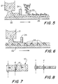
- FIG. 5 of the drawings A binder phase-powder composition 21 is dispensed onto a surface 22, and doctored to a uniform thickness by a doctor blade 24 to form a substrate 26.
- superabrasive particles 25 are dispensed onto the surface of the substrate 26. It will be understood that the composition 21 is not cured at the time the superabrasive particles 25 are placed onto the substrate 26, so the particles will be adhered thereto.
- pressure can be applied to assist in urging the superabrasive particles 25 at least partially into the substrate 26. Also, additional adhesives or the like can be applied as needed.
- Fig. 6 illustrates a modification of the arrangement shown in Fig. 5.
- the binder phase-powder composition 21 is dispensed onto the surface 22 and doctored to the desired thickness by doctor blade 24.
- the surface 22 carries a plurality of superabrasive particles 28, and the binder phase-powder composition is dispensed onto the particles 28.
- the superabrasive particles 28 may be completely covered, or only partially covered by the binder phase-powder composition as desired.
- Fig. 7 shows a substrate 10 having superabrasive particles 14 therein.
- the thickness t of the substrate may be equal to 3d to 10d, where d is the dimension of the superabrasive particles in the direction of the thickness of the substrate.
- Fig. 8 After curing the substrate to form a SEDF preform and sintering, the same is shown in Fig. 8. It will of course be realized that the superabrasive particles 14 will not change in size during sintering, but the preform will be significantly condensed.
- the weight of the dry retaining powder per unit volume of the SEDF preform determines the thickness of the sintered abrasive material, it being realized that the binder of the binder phase will run off, or evaporate, during sintering or other heat processing.
- the density of cobalt is 8.9 g/cm 3
- a cobalt preform contains 0.8 g/cm 2 of the dry cobalt powder; therefore, the thickness of the fully densified, sintered product will be about 0.9 mm, which is found by dividing 0.8 g/cm 2 by 8.9 g/cm 3 .
- the thickness of the SEDF preform is not in the calculation, this being irrelevant. The important consideration is the quantity of the dry powder per unit area of the preform.
- a plurality of trays 29 is moved under a hopper 30 which dispenses the binder phase-powder composition.
- Each tray 29 will receive a predetermined quantity of the composition to ultimately provide SEDF preforms of predetermined weight.
- the trays 29 can be placed on a conveyor 31, or may be part of a conveyor 31 which can move continuously, or intermittently, and timed so the binder phase in the composition will be cured before the preforms are removed from the trays 29.
- the preforms are received by another conveyor 32 which will carry the preforms to the next processing step.
- the conveyor 31 can take various geometrical arrangements, including a zig-zag shape in the horizontal plane and a stepped shape in vertical plane.
- the layer, with or without superabrasive particles thereon can be placed in the bottom of the trays 29. Also, superabrasive particles, with or without a layer, can be placed on top of the composition after the tray 29 is filled to the desired extent.
- SEDF preform may be made in the form of discrete plates as shown in Fig. 9, or may be made in the form of continuous tapes as shown in Figs. 5 and 6. Either form can then be cut easily with scissors, paper cutter, die cutting or the like.
- Fig. 10 of the drawings shows the preferred means and method for heating an SEDF preform and condensing the preform.
- Fig. 10 illustrates a generally conventional sinter fixture for sintering under pressure. It will be seen that there is a bottom punch 34 and a top punch 35, the space between the punches 34 and 35 being closed by the side plates 36. Within the cavity so defined, there is an SEDF preform 38, here shown as having superabrasive particles 39 distributed therein, and a plurality of superabrasive particles 40 on the top side of the preform 38.
- the punches 34 and 35 will be urged towards each other as indicated by the arrows, and an electric current will be passed through the sinter fixture and/or the preform to heat the preform.
- An important feature of the present method is that the side plates 36 will tend to restrain lateral movement of the SEDF preform during sintering, even though there may be a flow of liquid as the binder and/or retaining matrix melt and run.
- a further advantage of the SEDF preform in a sintering fixture as shown in Fig. 10 is that the softness of the preform makes redistribution of material quite easy. As a result, variations in thickness and stress can be made uniform simply through the usual pressure on the preform during sintering. The preform therefore has less sensitivity to various non- uniformities, and tends to reduce damage to the sinter molds. The inventor has experienced a 50-fold reduction in consumption of graphite mold parts since using the technique disclosed herein. It should be noted that, because of the softness and deformability of the SEDF preform, abrasive articles with a corrugated shape can be mass produced without significant consumption of corrugated (hence expensive) punches, e.g. graphite or metal punches.
- the sinter mold can be loaded with several assemblies of SEDF preforms, the assemblies being separated from one another by punches and/or separators as disclosed in U. S. Patent No. 5,203,880, "Method and Apparatus for Making Abrasive Tools", by the present inventor.
- Such sintering "in stock” is illustrated in Fig. 10A.
- the unique uniformity, softness and deformability of the SEDF preform make sintering in stock acceptable for mass production technology.
- the heating of the SEDF preforms under pressure has many advantages, there is one severe disadvantage: the heating melts and vaporizes the binder, which runs; and, the liquid or vaporized binder, intensified by the applied pressure, tends to carry the retaining powder and superabrasive particles out of the mold. If most of the retaining powder is washed out of the mold, there will of course be practically no matrix material to hold the left over superabrasive particles in place. Also, melted binder and/or melted or moved retaining matrix of SEDF preform will catch the superabrasive particles, which can be washed out of the mold.
- porous layer can be placed against the SEDF preform to prevent lateral movement of the particles.
- the porous layer may take many forms, but will not be held together by a binder as used in the SEDF preform. Rather, the porous layer may be screen wire, a conventional compacted preform, egg-crate or reticulated metal structures or the like.
- the superabrasive particles 41 are larger than the openings in the porous layer 42. Under pressure, the particles 41 may cut into the porous layer 42.
- the particles 44 of the retaining powder are smaller than the opening in the layer 42, so these particles will pass easily into the openings of the layer 42.
- porous layer 45 there is a second porous layer 45 on the opposite side of the SEDF preform; and, the assembly shown in Fig. 11 will be urged together and heated under pressure.
- the porous layers 42 and 45 will support the superabrasive particles and prevent lateral movement (perpendicular to the direction of the applied compaction force), and will provide additional volume to receive the SEDF preform, and restrain lateral motion of the particles of retaining powder in the SEDF preform.
- the porous layers will also temporarily absorb liquid binder to reduce the flow of binder and thereby help prevent washout of retaining powder and superabrasive particles.
- the porous layer, or layers, can be placed in various positions relative to the SEDF preform and other layers of an assembly to be sintered.
- Fig. 12 shows the SEDF preform 46 having a porous layer 48 on one side, and a layer of abrasive particles 49 on the opposite side of the porous layer 48, a substrate, or carrier 50 holding the particles 49 in place.
- Fig. 13 shows the same arrangement, but the substrate 50 is between the particles 49 and the porous layer 48.
- Fig. 14 shows the SEDF preform 46 in the middle with the porous layer 48 on one side, and the superabrasive particles 49 and substrate 50 on the opposite side.
- Fig. 15 shows the superabrasive particles 49 and substrate in the middle, with the SEDF preform 46 on one side, and the porous layer 48 on the opposite side.
- Fig. 16 is like Fig. 15, except that the positions of the superabrasive particles 49 and the substrate 50 are reversed.
- Fig. 17 shows two SEDF preforms 46 and 46'.
- a porous layer 48 is between the preforms, and the superabrasive particles 49 with the substrate 50 are on the opposite side of one of the preforms.
- the porous layer may take the form of a woven mesh, a nonwoven material, expanded foil, knitted materials and textile fabrics. Also, a material that is roll-compacted, extruded, sintered or the like can be used. Virtually any material can be used so long as the material is highly porous (about 30% to 99.5% porosity), having pores open to the surface and interconnected, with sufficient integrity to support the superabrasive particles and to restrain motion of the retaining powder in the process of sintering.
- porous layers are metallic non-woven materials, and particularly a nickel fiber powder non-woven mat, manufactured by National Standard, Woven production Division, Corbin KY, and sold under the trademark "Fibrex".
- the porosity of this mat is 85-98%; the fiber is 20 microns in diameter and is about 80 weight percent of the mat, while the powder is about 20 weight percent.
- copper wire mesh in the range of 20 to 200 mesh, works well as the porous layer.
- Some expanded metals manufactured by Delker Corporation have been used, for the same purpose.
- Fig. 18 of the drawings illustrate an SEDF preform 51 after the preform 51 has been urged against a porous layer 52.
- the porous layer 52 is here shown as having some substantial thickness, and being made up of a plurality of cells 54 so the porous layer 52 comprises a cellular type of material. It will be seen, then, that the material of the preform 51 has been urged into the cells 54. It has been found desirable in some cases to compress the preform 51 with the porous layer 52 prior to applying heat and pressure during sintering. The material of the preform 51, being received in the openings, or cells, 54 of the porous layer 42, tends to stay within the openings and not to move laterally.
- a porous layer 52 can be made of a material having a melting point below the sintering temperatures.
- the porous layer will melt onto the preform, and thereby modify the retaining composition.
- a cobalt-nickel SEDF preform may utilize a porous layer made of copper, bronze, brass, zinc, aluminum, or various combinations of these, as well as other porous layers.
- porous layer 52 may be conduction of heat and/or electricity during heating of the preform.
- a mesh or expanded foil of copper will readily conduct heat or electricity to facilitate uniform heating.
- the porous layer may include superabrasive particles within the cells 54.
- a preform as shown in Fig. 18 may be placed against a porous layer 52 having superabrasive particles therein, or the porous layer may be used as a substrate in an arrangement such as that shown in Fig. 6 of the drawings.
- Fig. 19 of the drawings it will be seen that the SEDF preform of the present invention is admirably suited to mass production techniques.
- the arrangement shown in Fig. 19 includes rolls 55 and 56 for assembling a plurality of layers to be sintered.
- a roll of a porous layer 60 is placed between the preform 58 and the substrate 59.
- the substrate 59 may have a plurality of superabrasive particles 61 previously placed thereon; or, as here illustrated, a dispenser 62 may place superabrasive particles on the substrate 59 during the assembling process. In either case it is contemplated that the substrate, or carrier, 59 will have an adhesive to hold the superabrasive particles 61 temporarily.
- the SEDF preform 58 may take many forms as discussed above.
- the preform 58 may include a plurality of superabrasive and abrasive particles, or may not. Further, the preform may be placed on a substrate in order to give the preform greater integrity.
- the porous layer 60 may or may not be included in the assembly.
- the preform 58 may utilize a porous layer as a substrate, or carrier, and this may be sufficient for some products. However, if one or more additional porous layers are desired, they may be fed to the assembly as shown in Fig. 19.
- Fig. 19 also shows separators 66 and 67.
- separators are disclosed in U. S. patent No. 5,203,880, "Method and Apparatus for Making Abrasive Tools", by the present inventor. In accordance with the disclosure in that patent, these separators assist in protrusion of the superabrasive particles through the retaining matrix, and in distribution of the temperature within the sinter mold during the sintering process.
- These separators 66 and 67 may or may not be attached to the SEDF preform assembly. When attached to the preform, the separators will be part of the assembly itself.
- separators such as the separators 66 and 67 may or may not be used. If separators are used, they may also be utilized as the substrate for SEDF preform (see numeral 22 in Figs. 5 and 6). It should be understood that, in the majority of the figures in the drawings, separators are not shown for the sake of simplification of the illustration.
- rolls 55 and 56 will urge the layers 58, 59 and 60, and separators 66 and 67 together into a single assembly 64. It is contemplated that the assembly 64 will then be cut into discrete pieces, or plates, 65 by a cutter 66.
- the individual plates 65 can be received by a conveyer 68 for transport to means for sintering.
- Figs. 20 and 21 of the drawings show one assembly and one resulting sintered abrasive material respectively in accordance with the present invention.
- SEDF preform 70 having superabrasive particles 71 distributed therein.
- SEDF preform 72 without abrasive particles.
- additional preforms 74 and 75 both having superabrasive particles distributed therein.
- a porous layer 76 between the preforms 70 and 74 there is a porous layer 76; and between the preforms 74 and 75 there is a porous layer 78.
- Fig. 21 it can be seen that the superabrasive particles remain in layers; and, on one side, the superabrasive particles 71 are at the surface of the sintered assembly, while on the opposite side the preform 72 provides a backing without superabrasive particles.
- This sintered abrasive material can now be used to manufacture cutting and grinding tools.
- the SEDF preform may have a profiled shape, which may or may not correspond to the shape of a compacting means, e.g. punches used for providing pressure during sintering.
- the profiled SEDF preform, along with the non-profiled, or flat ones, are utilized by the present inventor for manufacturing abrasive articles according to U. S. patent No. 5,190,568 titled "Abrasive Tool with Contoured Surface".
- Fig. 19A illustrates a one-sided profiled SEDF preform.
- One-way to manufacture the one-sided profiled SEDF preform includes the use of a profiled substrate 111, a binder-powder composition 112 being poured onto the substrate 111.
- Fig. 19B illustrates the formation of a two-sided profiled SEDF preform.
- Fig. 19B shows two substrates, or walls, 114 and 115 and a binder-powder composition 116 between the walls 114 and 115.
- the two-sided profiled SEDF preform is manufactured by pouring a binder-powder slurry between the two profiled walls 114 and 115, resulting in the formation of the two-sided profiled SEDF preform 116.
- wall 114 and wall 115 may have different profiles, and each side of the SEDF preform has a profile corresponding to the profile (relief) of the respective wall. It also should be understood that the walls can be positioned vertically or horizontally; and, application of pressure and/or changing the distance between the walls in the process of solidification of the binder-powder composition 116 are optional.
- a non-profiled, or flat, SEDF preform can be converted prior to sintering into a profiled one.
- the flat profile 118 can be shaped between profiled compacting means.
- Fig. 19C illustrates one of the processes for shaping a flat SEDF preform 118 into a profiled SEDF preform 119 by two profiled rolls or gears 120 and 121.
- the preferable arrangement does not require change of the thickness of the SEDF preform as a result of the shaping. This type of shaping does not require very great pressure because of the easy deformability of the SEDF preform.
- Fig. 20 also-shows separators 66a and 67a placed against SEDF preforms 70 and 72 as a part of the assembly itself.
- Fig. 21 does not show these separators, indicating that at least some of the separators have been removed from the sintered abrasive material in the process of after-sintering cleaning, or in the process of dressing the abrasive tool.
- Fig. 20A One method for utilization of the separators in combination with the SEDF preform is shown in Fig. 20A.
- the separator 100 is placed on one side of the assembly 103 that includes an SEDF preform 101, a layer of porous material 102 and a layer of superabrasive particles 104 on a substrate 105.
- a mesh type material 106 having openings 108 is applied against the separator 100; and, the preferable mesh type material 106 has orderly distributed openings 108.
- the assembly 103 Under pressure provided by one or both of the punches 35a and 35b, the assembly 103 extrudes at least partially into openings 108 of the mesh type material 106, de forming the separator 100 and leaving imprints on the surface of the assembly 103.
- the whole assembly 103 is put into the sintering mold as is shown in Figs. 10 and 10A, and then sintered, providing that sintering under pressure is preferable.
- the pressure to extrude the assembly 103 into the openings 108 can be applied prior to sintering, outside of the sinter mold and/or within this sinter mold, and/or in the process of sintering.
- the mesh type material 106 is removed from the mold, as well as the separator 100.
- the removal of the mesh type material 106 from the sintered abrasive article is not a problem because the separator 100 prevents diffusion between the assembly 103 and the mesh type material 106.
- the resulting abrasive article will comprise a profile corresponding to the design of the mesh type material 106.
- the mesh type material 106 can be placed against both sides of the SEDF preform 101 for making two-sided profiled abrasive article (see separator 109 in Fig. 20A); another separator 110 can be used to separate mesh type material 106 from the punch 35a, and separator 115 can be used to separate another side of the assembly 103 from the punch 35b. It also should be understood that several assemblies comprising SEDF preforms and the mesh material for extrusion can be sintered in stock as is shown in Fig. 10A. Furthermore, separators of different thicknesses and different types can be used for opposite sides of the SEDF preform 101.
- the mesh type material 106 for extrusion can be made from different materials, e.g. steel woven mesh, expanded metal, machined crags, honeycomb or the like. It is also preferable that openings in the mesh 106 be big enough to allow at least one superabrasive particle 104 to go therethrough. For example, diamonds have sizes of 0.015 to 0.200 mm (80-100 mesh) while the mesh type material for extrusion comprises openings of 1.00 to 0.850 mm (18 to 20 mesh). It is also preferable that the mesh type material 106 for extrusion does not melt under, sintering temperatures, and have a minimum deformability under the pressure that makes this mesh multiusable.
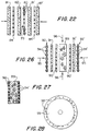
- Figs. 22 and 23 of the drawings show an assembly and a sintered single layer cutting tool respectively.
- Fig. 22 illustrates the layers to be assembled, and includes a central porous layer 79 having a plurality of superabrasive particles 80 in the openings thereof. It should be noticed that the particles 80 are at least as wide as the layer 79, so the particles 80 extend completely through the porous layer 79.
- Each side of the central layer 79 includes two SEDF preforms 81, 82 and 81', 82', separated by porous layers 84, 84'.
- abrasive article When the assembly is heated under pressure, the material shown in Fig. 23 results.
- the present inventor has used this method to produce abrasive articles with one layer of diamonds as shown. It should be understood, however, that the abrasive article can include as many layers as desired, in accordance with other disclosures herein.
- Figs. 24 and 25 show the production of a no-diamond foot on a conventional diamond segment.
- Current methods are difficult to use because the foot 85 is quite thin, requiring that powder be distributed very thinly, yet very uniformly, in a sinter mold.
- an SEDF preform 86 can be placed against the segment 88, and the retaining powder is readily distributed uniformly. As is discussed in detail above, the final thickness of the foot 85 can be easily calculated.
- Figs. 26 and 27 show the use of a conventional green compact having randomly distributed abrasive and/or superabrasive particles in combination with preforms of the present invention, and porous layers having orderly arranged superabrasive particles.
- the central green compact 89 has a porous layer 90, 90' on each side thereof, then an SEDF preform 91, 91'.
- the outside comprises a porous, or cellular, layer 92, 92' having a plurality of superabrasive particles 94, 94' distributed therein in an orderly fashion.
- the assembly of Fig. 26 can be compressed in the direction indicated by the arrows 95, or in the direction indicated by the arrows 96.
- the inventor has used this technique, with pressure in the direction of the arrows 95, to manufacture diamond segments for saw blades, and a ream saw blade.
- Fig. 28 illustrates the making of a cut-off disk.
- Individual pieces 98, or a complete ring, of the SEDF preform can be prepared of the proper shape, and placed around the periphery of a core 99. From the foregoing discussion it will be understood that the pieces 98 may include any number of layers, may or may not include porous layers, and may have as many or as few superabrasive particles as desired.
- the assembly will be sintered (preferably under pressure) so the sintering of the preform and fixing the preform to the core 99 are performed in one step.
- the preferred embodiments of the invention here presented comprise assemblies of superabrasive particles such as diamonds, cubic boron nitride or the like, distributed in an orderly fashion on a substrate, or a carrier, and a pre-made SEDF preform formed from metals, ceramics, epoxy materials with binders or other plastics.
- the assemblies of the above components are heated or sintered, preferably under an external pressure.
- the SEDF preform may or may not include randomly distributed superabrasive particles therein; and, and a separator can be a part of the assembly itself to prevent contacting and/or diffusion between the SEDF preforms and the molding parts.
Landscapes
- Engineering & Computer Science (AREA)
- Manufacturing & Machinery (AREA)
- Mechanical Engineering (AREA)
- Polishing Bodies And Polishing Tools (AREA)
- Processing And Handling Of Plastics And Other Materials For Molding In General (AREA)
- Powder Metallurgy (AREA)
Claims (59)
- Procédé de fabrication d'un article abrasif, dans lequel une pluralité de particules abrasives et une quantité de matériau de matrice pulvérulente susceptible d'être fritté sont combinés ensemble et frittés pour former l'article,
caractérisé en ce qu'il permet :de fournir un mélange de ladite quantité de matériau de matrice pulvérulente susceptible d'être fritté et d'une phase de liant liquide, le volume de la phase de liant liquide dans le mélange étant supérieur au volume du matériau de matrice susceptible d'être fritté, de former un préformé mou, pouvant facilement se déformer et flexible à partir dudit mélange, de placer une pluralité de particules abrasives au moins partiellement dans ledit préformé, puis de fritter ledit préformé pour former ledit article abrasif. - Procédé selon la revendication 1, dans lequel le préformé est fritté sous pression.
- Procédé selon la revendication 1, dans lequel la pluralité de particules abrasives est placée dans le préformé par combinaison des particules avec le mélange du matériau de matrice pulvérulent susceptible d'être fritté et de la phase de liant liquide avant de former ledit préformé.
- Procédé selon la revendication 1, dans lequel la pluralité de particules abrasives est placée dans le préformé en plaçant les particules d'un côté au moins dudit préformé, puis en forçant les particules dans ledit préformé.
- Procédé selon la revendication 4, dans lequel les particules abrasives sont forcées dans le préformé avant que le préformé soit fritté.
- Procédé selon la revendication 4, dans lequel les particules abrasives sont forcées dans le préformé pendant le frittage du préformé.
- Procédé selon la revendication 1, dans lequel les particules abrasives sont réparties de façon aléatoire dans ledit préformé.
- Procédé selon la revendication 1, dans lequel les particules abrasives sont réparties dans le préformé selon un motif non aléatoire.
- Procédé selon la revendication 1, dans lequel une partie des particules abrasives est répartie de façon aléatoire dans ledit préformé et une autre partie est répartie de façon non aléatoire d'un côté au moins dudit préformé, puis est forcé dans ledit préformé.
- Procédé selon la revendication 1, dans lequel ledit préformé mou, pouvant facilement se déformer et flexible est formé à partir d'une suspension ou d'une pâte dudit mélange de matériau de matrice susceptible d'être fritté pulvérulent et de phase de liant liquide, ladite phase de liant liquide comprenant au moins un liant et au moins un composant liquide volatil de celui-ci, le volume de la phase de liant liquide dans le mélange étant supérieur au volume du matériau de matrice frittable pulvérulent, la suspension ou la pâte étant formée en un substrat sur une surface de support, ce substrat étant ensuite durci pour éliminer au moins une partie du composant liquide volatil de celui-ci et pour former ledit préformé.
- Procédé selon la revendication 10, dans lequel la pluralité de particules abrasives est placée dans le préformé en plaçant les particules sur la surface du support avant que le substrat soit formé sur celui-ci.
- Procédé selon la revendication 11, dans lequel les particules abrasives sont réparties de façon aléatoire sur la surface du support.
- Procédé selon la revendication 11, dans lequel les particules abrasives sont réparties sur la surface du support selon un motif non aléatoire.
- Procédé selon la revendication 11, dans lequel la surface du support comprend une pluralité d'ouvertures s'étendant vers la surface de celui-ci et les particules abrasives sont placées dans les ouvertures de la surface du support.
- Procédé selon la revendication 10, dans lequel la pluralité de particules abrasives est placée dans le préformé en plaçant les particules à la surface du substrat opposé à la surface du support avant que le substrat soit durci.
- Procédé selon la revendication 15, dans lequel les particules abrasives sont placées de façon aléatoire sur la surface du substrat.
- Procédé selon la revendication 15, dans lequel les particules abrasives sont placées sur la surface su substrat selon un motif non aléatoire.
- Procédé selon la revendication 10, dans lequel la pluralité de particules abrasives est placée dans le préformé en plaçant les particules d'un côté du préformé après la formation dudit préformé, puis en forçant les particules dans ledit préformé.
- Procédé selon la revendication 2, comprenant le fait de placer au moins une couche poreuse contre un côté dudit préformé pour former un assemblage avant le frittage dudit préformé sous pression, ledit assemblage étant ensuite fritté sous pression, afin que ladite couche poreuse soit forcée dans ledit préformé, ladite couche poreuse ayant une pluralité d'ouvertures s'étendant vers la surface opposée de celle-ci pour limiter le mouvement dudit matériau de matrice susceptible d'être fritté et des particules abrasives pendant le frittage sous pression.
- Procédé selon la revendication 19, dans lequel les particules abrasives sont placées dans le préformé en plaçant les particules d'un côté de la couche poreuse, les particules et la couche poreuse étant forcées dans le préformé pour placer au moins partiellement la pluralité de particules abrasives dans ledit préformé pendant le frittage de l'assemblage sous pression.
- Procédé selon la revendication 19, dans lequel l'assemblage comprend un deuxième préformé placé contre un côté de ladite couche poreuse opposé audit côte de ladite couche poreuse avant le frittage dudit assemblage, afin que ladite couche poreuse soit forcée dans lesdits deux préformés pendant le frittage de l'assemblage sous pression.
- Procédé selon la revendication 19, dans lequel le préformé est formé sur une surface de ladite couche poreuse.
- Procédé selon la revendication 22, dans lequel les particules abrasives sont placées dans le préformé en plaçant les particules sur la couche poreuse avant que le préformé soit formé sur la couche poreuse.
- Procédé selon la revendication 19, dans lequel la couche poreuse a une température de fusion inférieure à celle du matériau de matrice susceptible d'être fritté.
- Procédé selon la revendication 24, dans lequel la couche poreuse fond au moins partiellement pendant le frittage de l'assemblage.
- Procédé selon la revendication 19, dans lequel l'assemblage comprenant une deuxième couche poreuse placée contre un côté dudit préformé opposé audit côté dudit préformé avant le frittage dudit assemblage, afin que les deux couches poreuses soient forcées dans ledit préformé pendant le frittage de l'assemblage sous pression.
- Procédé selon la revendication 19, comprenant le fait de placer au moins une couche de matériau de séparation au moins d'un côté dudit assemblage avant le frittage dudit assemblage sous pression, puis de retirer la couche de matériau de séparation dudit assemblage.
- Procédé selon la revendication 27, comprenant le fait de placer une deuxième couche de matériau de séparation du côté opposé audit côté dudit assemblage avant le frittage dudit assemblage sous pression, puis de retirer ladite deuxième couche de matériau de séparation dudit assemblage.
- Procédé selon la revendication 27, comprenant le fait de placer au moins une couche de matériau de tamis contre ladite couche de matériau de séparation avant le frittage, afin que le matériau de tamis soit forcé à travers ladite couche de matériau de séparation dans ledit assemblage pendant le frittage de l'assemblage sous pression pour former un profilé du matériau de tamis d'un côté de l'assemblage, puis de retirer ladite couche de matériau de tamis et ladite couche de matériau de séparation dudit assemblage.
- Procédé selon la revendication 29, comprenant le fait de placer une deuxième couche de matériau de séparation d'un côté du matériau de tamis opposé audit assemblage avant le frittage de l'assemblage sous pression, puis de retirer les deux couches de matériau de séparation dudit assemblage.
- Procédé selon la revendication 29, dans lequel le matériau de tamis est un tamis métallique ayant un maillage ordonné.
- Procédé selon la revendication 29, dans lequel le matériau de tamis est un métal expansé.
- Procédé selon la revendication 2, comprenant le fait de placer au moins une couche de matériau de séparation d'un côté au moins dudit préformé avant le frittage dudit préformé sous pression, puis de retirer ladite couche de matériau de séparation dudit préformé.
- Procédé selon la revendication 33, comprenant le fait de placer une deuxième couche de matériau de séparation d'un côté dudit préformé opposé audit côté dudit préformé avant le frittage dudit préformé sous pression, puis de retirer ladite deuxième couche de matériau de séparation dudit préformé.
- Procédé selon la revendication 1, dans lequel l'épaisseur du préformé avant son frittage est de 3 à 10 fois la granulométrie des particules abrasives.
- Procédé selon la revendication 10, dans lequel le volume du matériau de matrice pulvérulent susceptible d'être fritté dans ledit mélange constitue de 0,3 à 10%.
- Procédé selon la revendication 10, dans lequel le poids de la phase de liant liquide dans ledit mélange constitue de 3 à 20%.
- Procédé selon la revendication 37, dans lequel le poids de la phase de liant liquide dans ledit mélange est de 5,0 à 8,5%.
- Procédé selon la revendication 10, dans lequel le liant est un ciment de caoutchouc.
- Procédé selon la revendication 30, comprenant le fait de placer une troisième couche de matériau de séparation d'un côté dudit assemblage opposé audit côté dudit assemblage avant le frittage dudit assemblage sous pression, puis de retirer ladite troisième couche de matériau de séparation dudit assemblage.
- Procédé selon la revendication 29, comprenant le fait de placer une deuxième couche de matériau de séparation du côté dudit assemblage opposé audit côté dudit assemblage et de placer une deuxième couche de matériau de tamis adjacente à ladite deuxième couche de matériau de séparation avant le frittage, afin que les deux couches de matériau de tamis soient forcées à travers les couches de matériau de séparation adjacentes respectives dans ledit assemblage pendant le frittage de l'assemblage sous pression afin qu'un profilé du matériau de tamis soit formé des deux côtés de l'assemblage, puis de retirer lesdites deux couches de matériau de tamis et de séparation.
- Procédé selon la revendication 41, dans lequel chaque couche de matériau de séparation a une épaisseur différente.
- Procédé selon la revendication 41, dans lequel chaque couche de matériau de tamis est constituée d'un matériau différent.
- Procédé selon la revendication 33, comprenant le fait de placer au moins une couche de matériau de tamis adjacente à ladite couche de matériau de séparation avant le frittage, afin que le matériau de tamis soit forcé à travers ladite couche de matériau de séparation pendant le frittage du préformé sous pression pour former un profilé du matériau de tamis d'un côté du préformer, puis de retirer ladite couche de matériau de tamis et ladite couche de matériau de séparation dudit préformé.
- Procédé selon la revendication 44, dans lequel le matériau de tamis est un tamis métallique ayant un maillage ordonné.
- Procédé selon la revendication 44, dans lequel le matériau de tamis est un métal expansé.
- Procédé selon la revendication 44, comprenant le fait de placer une deuxième couche de matériau de séparation d'un côté du matériau de tamis opposé audit préformé avant le frittage du préformé sous pression, puis de retirer la deuxième couche de matériau de séparation dudit préformé.
- Procédé selon la revendication 47, comprenant le fait de placer une troisième couche de matériau de séparation d'un côté dudit préformé opposé audit côté dudit préformé avant le frittage dudit préformé sous pression, puis de retirer ladite troisième couche de matériau de séparation dudit préformé.
- Procédé selon la revendication 44, comprenant le fait de placer une deuxième couche de matériau de séparation du côté dudit préformé opposé audit côté dudit préformé et de placer une deuxième couche de matériau de tamis adjacente à ladite deuxième couche de matériau de séparation avant le frittage, afin que les deux couches de matériau de tamis soient forcées à travers les couches de matériau de séparation adjacentes respectives dans ledit préformé pendant le frittage du préformé sous pression, afin de former un profilé du matériau de tamis des deux côtés du préformé, puis de retirer lesdites deux couches de matériau de tamis et de séparation.
- Procédé selon la revendication 49, dans lequel chaque couche de matériau de séparation a une épaisseur différente.
- Procédé selon la revendication 49, dans lequel chaque couche de matériau de tamis est constituée d'un matériau différent.
- Procédé selon la revendication 2, dans lequel la pluralité de particules abrasives est placée dans le préformé par répartition aléatoire des particules dans une couche de matériau vert de matrice comprimé susceptible d'être fritté, le procédé comprenant l'étape consistant à placer un côté de cette couche contre ledit préformé pour former un assemblage, puis à fritter ledit assemblage sous pression pour former ledit article abrasif.
- Procédé selon la revendication 52, dans lequel l'assemblage comprend en outre un deuxième préformé placé du côté de ladite couche opposé audit côté de ladite couche de matériau vert de matrice comprimé susceptible d'être fritté avant le frittage dudit assemblage sous pression.
- Procédé selon la revendication 53, dans lequel l'assemblage comprend une couche de matériau poreux placée contre chacun desdits préformés, lesdites couches poreuses ayant des pores ouverts vers la surface de celles-ci et étant forcées dans lesdits préformés pendant le frittage dudit assemblage sous pression.
- Procédé selon la revendication 54, dans lequel des particules abrasives supplémentaires sont placées dans les couches poreuses de manière non aléatoire avant le frittage.
- Procédé selon la revendication 1, dans lequel la pluralité de particules abrasives est placée dans le préformé en appliquant un adhésif au moins sur certaines zones de la surface du préformé mou, pouvant facilement se déformer et flexible, en appliquant une pluralité de particules abrasives sur au moins lesdites zones adhésives, puis en forçant les particules abrasives dans ledit préformé.
- Procédé selon la revendication 56, dans lequel des particules abrasives ne collant pas aux zones adhésives sont éliminées de ladite surface du préformé avant que les particules abrasives soient forcées dans le préformé.
- Procédé selon la revendication 56 ou 57, dans lequel les particules abrasives sont forcées dans le préformé avant le frittage du préformé.
- Procédé selon la revendication 56 ou 57, dans lequel les particules abrasives sont forcées dans le préformé pendant le frittage du préforme.
Applications Claiming Priority (3)
| Application Number | Priority Date | Filing Date | Title |
|---|---|---|---|
| US22525194A | 1994-04-08 | 1994-04-08 | |
| US225251 | 1994-04-08 | ||
| PCT/US1995/001503 WO1995027596A1 (fr) | 1994-04-08 | 1995-02-10 | Procede pour fabriquer des preformes de poudres et des articles abrasifs a partir de ces preformes |
Publications (2)
| Publication Number | Publication Date |
|---|---|
| EP0754106A1 EP0754106A1 (fr) | 1997-01-22 |
| EP0754106B1 true EP0754106B1 (fr) | 2000-05-10 |
Family
ID=22844157
Family Applications (1)
| Application Number | Title | Priority Date | Filing Date |
|---|---|---|---|
| EP95908805A Expired - Lifetime EP0754106B1 (fr) | 1994-04-08 | 1995-02-10 | Procede pour fabriquer des preformes de poudres et des articles abrasifs a partir de ces preformes |
Country Status (14)
| Country | Link |
|---|---|
| US (1) | US5620489A (fr) |
| EP (1) | EP0754106B1 (fr) |
| JP (1) | JP3294277B2 (fr) |
| KR (1) | KR100310788B1 (fr) |
| CN (1) | CN1094087C (fr) |
| AT (1) | ATE192686T1 (fr) |
| AU (1) | AU682932B2 (fr) |
| CA (1) | CA2186481C (fr) |
| DE (1) | DE69516863T2 (fr) |
| DK (1) | DK0754106T3 (fr) |
| ES (1) | ES2148490T3 (fr) |
| TW (1) | TW252936B (fr) |
| WO (1) | WO1995027596A1 (fr) |
| ZA (1) | ZA9410384B (fr) |
Cited By (2)
| Publication number | Priority date | Publication date | Assignee | Title |
|---|---|---|---|---|
| EP2105256A1 (fr) | 2008-03-28 | 2009-09-30 | Cedric Sheridan | Procédé et appareil pour former des grains abrasifs agrégés pour la production d'outils abrasifs ou coupants |
| EP2368959A1 (fr) | 2010-03-23 | 2011-09-28 | Cedric Sheridan | Abrasifs agrégés pour la production d'outils abrasifs ou coupants |
Families Citing this family (71)
| Publication number | Priority date | Publication date | Assignee | Title |
|---|---|---|---|---|
| US5766394A (en) * | 1995-09-08 | 1998-06-16 | Smith International, Inc. | Method for forming a polycrystalline layer of ultra hard material |
| US9463552B2 (en) | 1997-04-04 | 2016-10-11 | Chien-Min Sung | Superbrasvie tools containing uniformly leveled superabrasive particles and associated methods |
| US6679243B2 (en) | 1997-04-04 | 2004-01-20 | Chien-Min Sung | Brazed diamond tools and methods for making |
| US9868100B2 (en) | 1997-04-04 | 2018-01-16 | Chien-Min Sung | Brazed diamond tools and methods for making the same |
| US20040112359A1 (en) * | 1997-04-04 | 2004-06-17 | Chien-Min Sung | Brazed diamond tools and methods for making the same |
| US9238207B2 (en) | 1997-04-04 | 2016-01-19 | Chien-Min Sung | Brazed diamond tools and methods for making the same |
| US9199357B2 (en) | 1997-04-04 | 2015-12-01 | Chien-Min Sung | Brazed diamond tools and methods for making the same |
| US7368013B2 (en) * | 1997-04-04 | 2008-05-06 | Chien-Min Sung | Superabrasive particle synthesis with controlled placement of crystalline seeds |
| US9409280B2 (en) | 1997-04-04 | 2016-08-09 | Chien-Min Sung | Brazed diamond tools and methods for making the same |
| US7124753B2 (en) * | 1997-04-04 | 2006-10-24 | Chien-Min Sung | Brazed diamond tools and methods for making the same |
| US7323049B2 (en) * | 1997-04-04 | 2008-01-29 | Chien-Min Sung | High pressure superabrasive particle synthesis |
| US9221154B2 (en) | 1997-04-04 | 2015-12-29 | Chien-Min Sung | Diamond tools and methods for making the same |
| US6110031A (en) * | 1997-06-25 | 2000-08-29 | 3M Innovative Properties Company | Superabrasive cutting surface |
| US6196911B1 (en) | 1997-12-04 | 2001-03-06 | 3M Innovative Properties Company | Tools with abrasive segments |
| US6358133B1 (en) | 1998-02-06 | 2002-03-19 | 3M Innovative Properties Company | Grinding wheel |
| US6159087A (en) * | 1998-02-11 | 2000-12-12 | Applied Materials, Inc. | End effector for pad conditioning |
| US6416560B1 (en) | 1999-09-24 | 2002-07-09 | 3M Innovative Properties Company | Fused abrasive bodies comprising an oxygen scavenger metal |
| US7201645B2 (en) * | 1999-11-22 | 2007-04-10 | Chien-Min Sung | Contoured CMP pad dresser and associated methods |
| US6551176B1 (en) | 2000-10-05 | 2003-04-22 | Applied Materials, Inc. | Pad conditioning disk |
| US8545583B2 (en) * | 2000-11-17 | 2013-10-01 | Wayne O. Duescher | Method of forming a flexible abrasive sheet article |
| US6575353B2 (en) * | 2001-02-20 | 2003-06-10 | 3M Innovative Properties Company | Reducing metals as a brazing flux |
| US6669745B2 (en) | 2001-02-21 | 2003-12-30 | 3M Innovative Properties Company | Abrasive article with optimally oriented abrasive particles and method of making the same |
| US7073496B2 (en) * | 2003-03-26 | 2006-07-11 | Saint-Gobain Abrasives, Inc. | High precision multi-grit slicing blade |
| US20070026754A1 (en) * | 2003-04-25 | 2007-02-01 | Carmen Martin Rivera | Scouring material |
| KR100551216B1 (ko) | 2004-06-22 | 2006-02-09 | 신한다이아몬드공업 주식회사 | 테이프 캐스팅법을 이용한 다이아몬드 그린테이프의제조방법 및 다이아몬드 그린테이프 |
| US7089925B1 (en) | 2004-08-18 | 2006-08-15 | Kinik Company | Reciprocating wire saw for cutting hard materials |
| US7258708B2 (en) * | 2004-12-30 | 2007-08-21 | Chien-Min Sung | Chemical mechanical polishing pad dresser |
| KR100623304B1 (ko) * | 2005-04-14 | 2006-09-13 | 이화다이아몬드공업 주식회사 | 절삭팁, 절삭팁의 제조방법 및 절삭공구 |
| KR100680850B1 (ko) * | 2005-04-20 | 2007-02-09 | 이화다이아몬드공업 주식회사 | 다이아몬드 공구용 절삭팁 및 다이아몬드 공구 |
| KR100764912B1 (ko) * | 2005-04-21 | 2007-10-09 | 이화다이아몬드공업 주식회사 | 절삭공구용 절삭팁 및 절삭공구 |
| US8622787B2 (en) * | 2006-11-16 | 2014-01-07 | Chien-Min Sung | CMP pad dressers with hybridized abrasive surface and related methods |
| US9724802B2 (en) | 2005-05-16 | 2017-08-08 | Chien-Min Sung | CMP pad dressers having leveled tips and associated methods |
| US8398466B2 (en) * | 2006-11-16 | 2013-03-19 | Chien-Min Sung | CMP pad conditioners with mosaic abrasive segments and associated methods |
| US8393934B2 (en) | 2006-11-16 | 2013-03-12 | Chien-Min Sung | CMP pad dressers with hybridized abrasive surface and related methods |
| US9138862B2 (en) | 2011-05-23 | 2015-09-22 | Chien-Min Sung | CMP pad dresser having leveled tips and associated methods |
| US8678878B2 (en) | 2009-09-29 | 2014-03-25 | Chien-Min Sung | System for evaluating and/or improving performance of a CMP pad dresser |
| TWI290337B (en) * | 2005-08-09 | 2007-11-21 | Princo Corp | Pad conditioner for conditioning a CMP pad and method of making the same |
| US7883398B2 (en) * | 2005-08-11 | 2011-02-08 | Saint-Gobain Abrasives, Inc. | Abrasive tool |
| US7840305B2 (en) * | 2006-06-28 | 2010-11-23 | 3M Innovative Properties Company | Abrasive articles, CMP monitoring system and method |
| EP2057244B1 (fr) * | 2006-09-01 | 2010-05-12 | Cedric Sheridan | Produit intermédiaire s'utilisant pour la fabrication d'outils d'abrasion ou de coupe |
| US20080092714A1 (en) * | 2006-10-09 | 2008-04-24 | Texas Instruments Incorporated | Multilayer dicing blade |
| TW200904591A (en) * | 2007-07-18 | 2009-02-01 | Kinik Co | Polishing tool having brazing filler layer made from spraying molding and processing method utilizing the same |
| JP4584971B2 (ja) * | 2007-10-09 | 2010-11-24 | 株式会社ナノテム | 研削砥石の製造方法 |
| TWI388402B (en) | 2007-12-06 | 2013-03-11 | Methods for orienting superabrasive particles on a surface and associated tools | |
| US8252263B2 (en) * | 2008-04-14 | 2012-08-28 | Chien-Min Sung | Device and method for growing diamond in a liquid phase |
| GB0818186D0 (en) * | 2008-10-06 | 2008-11-12 | 3M Innovative Properties Co | Scouring material comprising natural fibres |
| US8496511B2 (en) | 2010-07-15 | 2013-07-30 | 3M Innovative Properties Company | Cathodically-protected pad conditioner and method of use |
| US8616847B2 (en) * | 2010-08-30 | 2013-12-31 | Siemens Energy, Inc. | Abrasive coated preform for a turbine blade tip |
| CN103221180A (zh) | 2010-09-21 | 2013-07-24 | 铼钻科技股份有限公司 | 具有基本平坦颗粒尖端的超研磨工具及其相关方法 |
| CN102001056B (zh) * | 2010-09-27 | 2012-08-15 | 安泰科技股份有限公司 | 一种钎焊-热压烧结金刚石工具及其制造方法 |
| JP5691777B2 (ja) | 2011-04-14 | 2015-04-01 | 株式会社Ihi | 粉末圧延装置及び粉末圧延方法 |
| WO2012162430A2 (fr) | 2011-05-23 | 2012-11-29 | Chien-Min Sung | Tampon de polissage mécano-chimique (cmp) à pointes nivelées et procédés associés |
| US9089946B1 (en) | 2012-02-14 | 2015-07-28 | Jeff Toycen | Low speed high feed grinder |
| US10300581B2 (en) | 2014-09-15 | 2019-05-28 | 3M Innovative Properties Company | Methods of making abrasive articles and bonded abrasive wheel preparable thereby |
| WO2016064726A1 (fr) | 2014-10-21 | 2016-04-28 | 3M Innovative Properties Company | Préformes abrasives, procédé de fabrication d'article abrasif, et article abrasif lié |
| US10086500B2 (en) * | 2014-12-18 | 2018-10-02 | Applied Materials, Inc. | Method of manufacturing a UV curable CMP polishing pad |
| EP3257660A1 (fr) * | 2016-06-13 | 2017-12-20 | Siemens Aktiengesellschaft | Procédé de fourniture de moyens abrasifs et de fabrication d'un élément de manière additive |
| JP7134971B2 (ja) * | 2016-12-23 | 2022-09-12 | スリーエム イノベイティブ プロパティズ カンパニー | ポリマーボンド研磨物品及びそれらの製造方法 |
| JP7186770B2 (ja) * | 2017-10-04 | 2022-12-09 | サンーゴバン アブレイシブズ,インコーポレイティド | 研磨用物品およびその形成方法 |
| EP3670041A1 (fr) * | 2018-12-21 | 2020-06-24 | Hilti Aktiengesellschaft | Procédé de fabrication d'un segment de traitement pour le traitement à sec de matériaux de béton |
| WO2020128086A1 (fr) * | 2018-12-21 | 2020-06-25 | Hilti Aktiengesellschaft | Procédé pour fabriquer une ébauche crue et procédé pour transformer l'ébauche crue en segment d'usinage pour l'usinage à sec de matériaux de béton |
| EP3670036A1 (fr) * | 2018-12-21 | 2020-06-24 | Hilti Aktiengesellschaft | Procédé de fabrication d'un segment de traitement pour le traitement à sec de matériaux de béton |
| EP3670038A1 (fr) * | 2018-12-21 | 2020-06-24 | Hilti Aktiengesellschaft | Procédé de fabrication d'un segment de traitement pour le traitement à sec de matériaux de béton |
| EP3670037A1 (fr) * | 2018-12-21 | 2020-06-24 | Hilti Aktiengesellschaft | Procédé de fabrication d'un segment de traitement pour le traitement à sec des matériaux de béton |
| CN110125821B (zh) * | 2019-05-27 | 2021-08-17 | 福建省泉州市华钻金刚石工具有限公司 | 一种石材抛光用金属磨块及其制作方法 |
| EP3928896A1 (fr) * | 2020-06-24 | 2021-12-29 | Hilti Aktiengesellschaft | Procédé de fabrication d'une ébauche et procédé de traitement ultérieur de l'ébauche en un segment de traitement |
| EP3928905A1 (fr) * | 2020-06-24 | 2021-12-29 | Hilti Aktiengesellschaft | Procédé de fabrication d'une ébauche et procédé de traitement ultérieur de l'ébauche en un segment de traitement |
| EP3928903A1 (fr) * | 2020-06-24 | 2021-12-29 | Hilti Aktiengesellschaft | Procédé de fabrication d'un segment de traitement doté d'une projection de particules de matériau dur sur les surfaces latérales du segment de traitement |
| EP3928894A1 (fr) * | 2020-06-24 | 2021-12-29 | Hilti Aktiengesellschaft | Procédé de fabrication d'une ébauche et procédé de traitement ultérieur de l'ébauche en un segment de traitement |
| EP3928895A1 (fr) * | 2020-06-24 | 2021-12-29 | Hilti Aktiengesellschaft | Procédé de fabrication d'une ébauche et procédé de traitement ultérieur de l'ébauche en un segment de traitement |
| EP3928893A1 (fr) * | 2020-06-24 | 2021-12-29 | Hilti Aktiengesellschaft | Procédé de fabrication d'un segment de traitement doté d'une projection de particules de matériau dur sur la face supérieure |
Family Cites Families (27)
| Publication number | Priority date | Publication date | Assignee | Title |
|---|---|---|---|---|
| US2268663A (en) * | 1939-09-19 | 1942-01-06 | J K Smit & Sons Inc | Abrasive tool |
| US2876086A (en) * | 1954-06-21 | 1959-03-03 | Minnesota Mining & Mfg | Abrasive structures and method of making |
| US2811960A (en) * | 1957-02-26 | 1957-11-05 | Fessel Paul | Abrasive cutting body |
| US3127715A (en) * | 1960-04-27 | 1964-04-07 | Christensen Diamond Prod Co | Diamond cutting devices |
| US3276852A (en) * | 1962-11-20 | 1966-10-04 | Jerome H Lemelson | Filament-reinforced composite abrasive articles |
| FR2029390A1 (fr) * | 1969-01-24 | 1970-10-23 | Ferrand Marcel | |
| GB1375571A (fr) * | 1971-07-27 | 1974-11-27 | ||
| US3952782A (en) * | 1973-11-28 | 1976-04-27 | Colgate-Palmolive Company | Apparatus for filling containers with composite fluent material |
| DE2918103C2 (de) * | 1979-05-04 | 1985-12-05 | Sia Schweizer Schmirgel- & Schleifindustrie Ag, Frauenfeld | Verfahren zum Auftragen eines Grundbindemittels und Vorrichtung zur Durchführung desselben |
| US4409054A (en) * | 1981-01-14 | 1983-10-11 | United Technologies Corporation | Method for applying abradable material to a honeycomb structure and the product thereof |
| FR2565870B1 (fr) * | 1984-06-15 | 1988-05-13 | Triefus France Applic Indles | Procede de fabrication d'outils diamantes sur support souple et outils en resultant |
| US4634453A (en) * | 1985-05-20 | 1987-01-06 | Norton Company | Ceramic bonded grinding wheel |
| US4949511A (en) * | 1986-02-10 | 1990-08-21 | Toshiba Tungaloy Co., Ltd. | Super abrasive grinding tool element and grinding tool |
| US4680199A (en) * | 1986-03-21 | 1987-07-14 | United Technologies Corporation | Method for depositing a layer of abrasive material on a substrate |
| US4652277A (en) * | 1986-04-25 | 1987-03-24 | Dresser Industries, Inc. | Composition and method for forming an abrasive article |
| GB8713177D0 (en) * | 1987-06-05 | 1987-07-08 | Mixalloy Ltd | Producing strip |
| US4925457B1 (en) * | 1989-01-30 | 1995-09-26 | Ultimate Abrasive Syst Inc | Method for making an abrasive tool |
| US5190568B1 (en) * | 1989-01-30 | 1996-03-12 | Ultimate Abrasive Syst Inc | Abrasive tool with contoured surface |
| US5049165B1 (en) * | 1989-01-30 | 1995-09-26 | Ultimate Abrasive Syst Inc | Composite material |
| GB8915449D0 (en) * | 1989-07-06 | 1989-08-23 | Unicorn Ind Plc | Grinding tools |
| US5203881A (en) * | 1990-02-02 | 1993-04-20 | Wiand Ronald C | Abrasive sheet and method |
| US5160509A (en) * | 1991-05-22 | 1992-11-03 | Norton Company | Self-bonded ceramic abrasive wheels |
| US5221294A (en) * | 1991-05-22 | 1993-06-22 | Norton Company | Process of producing self-bonded ceramic abrasive wheels |
| US5143523A (en) * | 1991-09-20 | 1992-09-01 | General Electric Company | Dual-coated diamond pellets and saw blade semgents made therewith |
| US5203880B1 (en) * | 1992-07-24 | 1995-10-17 | Ultimate Abrasive Syst Inc | Method and apparatus for making abrasive tools |
| US5264011A (en) * | 1992-09-08 | 1993-11-23 | General Motors Corporation | Abrasive blade tips for cast single crystal gas turbine blades |
| ZA941116B (en) * | 1993-03-05 | 1994-08-30 | Smith International | Polycrystalline diamond compact |
-
1994
- 1994-12-29 ZA ZA9410384A patent/ZA9410384B/xx unknown
-
1995
- 1995-01-10 TW TW084100185A patent/TW252936B/zh not_active IP Right Cessation
- 1995-02-10 EP EP95908805A patent/EP0754106B1/fr not_active Expired - Lifetime
- 1995-02-10 WO PCT/US1995/001503 patent/WO1995027596A1/fr active IP Right Grant
- 1995-02-10 DK DK95908805T patent/DK0754106T3/da active
- 1995-02-10 JP JP52631795A patent/JP3294277B2/ja not_active Expired - Lifetime
- 1995-02-10 DE DE69516863T patent/DE69516863T2/de not_active Expired - Lifetime
- 1995-02-10 CA CA002186481A patent/CA2186481C/fr not_active Expired - Fee Related
- 1995-02-10 CN CN95192482A patent/CN1094087C/zh not_active Expired - Lifetime
- 1995-02-10 AU AU17000/95A patent/AU682932B2/en not_active Ceased
- 1995-02-10 AT AT95908805T patent/ATE192686T1/de not_active IP Right Cessation
- 1995-02-10 ES ES95908805T patent/ES2148490T3/es not_active Expired - Lifetime
- 1995-02-10 KR KR1019960705584A patent/KR100310788B1/ko not_active IP Right Cessation
-
1996
- 1996-01-31 US US08/594,388 patent/US5620489A/en not_active Expired - Lifetime
Cited By (5)
| Publication number | Priority date | Publication date | Assignee | Title |
|---|---|---|---|---|
| EP2105256A1 (fr) | 2008-03-28 | 2009-09-30 | Cedric Sheridan | Procédé et appareil pour former des grains abrasifs agrégés pour la production d'outils abrasifs ou coupants |
| EP2596911A1 (fr) | 2008-03-28 | 2013-05-29 | Cedric Sheridan | Procédé et appareil de formation des grains abrasifs agrégés destinés pour une utilisation dans la production d'outils d'abrasion ou de coupe |
| US8568497B2 (en) | 2008-03-28 | 2013-10-29 | Cedric Sheridan | Aggregate abrasive grains for abrading or cutting tools production |
| EP2368959A1 (fr) | 2010-03-23 | 2011-09-28 | Cedric Sheridan | Abrasifs agrégés pour la production d'outils abrasifs ou coupants |
| WO2011117244A1 (fr) | 2010-03-23 | 2011-09-29 | Sheridan Cedric | Abrasifs agrégés pour la fabrication d'outils d'abrasion ou de coupe |
Also Published As
| Publication number | Publication date |
|---|---|
| KR100310788B1 (ko) | 2001-12-15 |
| EP0754106A1 (fr) | 1997-01-22 |
| ZA9410384B (en) | 1996-02-01 |
| ATE192686T1 (de) | 2000-05-15 |
| CN1094087C (zh) | 2002-11-13 |
| JP3294277B2 (ja) | 2002-06-24 |
| AU682932B2 (en) | 1997-10-23 |
| DE69516863D1 (de) | 2000-06-15 |
| JPH10503428A (ja) | 1998-03-31 |
| ES2148490T3 (es) | 2000-10-16 |
| AU1700095A (en) | 1995-10-30 |
| DK0754106T3 (da) | 2000-10-02 |
| TW252936B (en) | 1995-08-01 |
| CA2186481C (fr) | 2002-11-26 |
| CA2186481A1 (fr) | 1995-10-19 |
| CN1145048A (zh) | 1997-03-12 |
| US5620489A (en) | 1997-04-15 |
| WO1995027596A1 (fr) | 1995-10-19 |
| DE69516863T2 (de) | 2000-10-12 |
Similar Documents
| Publication | Publication Date | Title |
|---|---|---|
| EP0754106B1 (fr) | Procede pour fabriquer des preformes de poudres et des articles abrasifs a partir de ces preformes | |
| AU717867B2 (en) | Patterned abrasive tools | |
| US6478831B2 (en) | Abrasive surface and article and methods for making them | |
| JP4287301B2 (ja) | パターン化された研磨材料およびその製造方法 | |
| US4908046A (en) | Multilayer abrading tool and process | |
| US5022895A (en) | Multilayer abrading tool and process | |
| US4945686A (en) | Multilayer abrading tool having an irregular abrading surface and process | |
| US5133782A (en) | Multilayer abrading tool having an irregular abrading surface and process | |
| EP1237679B1 (fr) | Surface et article abrasifs et leurs procedes de fabrication | |
| JPS6092406A (ja) | ボンドドレツサの製造法 | |
| US5139722A (en) | Method of forming concrete structures | |
| MXPA96004629A (en) | Method for making powder preform and abrasive articles made therefrom | |
| US2383519A (en) | Manufacture of abrasive articles | |
| JP3451903B2 (ja) | 薄刃砥石の製造方法 | |
| JPH11277442A (ja) | 薄刃砥石およびその製造方法 | |
| RU2309816C2 (ru) | Способ изготовления режущих элементов из сверхтвердых материалов | |
| MXPA99010461A (en) | Patterned abrasive tools | |
| JPS6322273A (ja) | 焼結型研摩体 | |
| JPH10146764A (ja) | 精密研削用砥石およびその製造方法 | |
| JPS61103782A (ja) | 遠心力を利用した砥石車の製造法 | |
| PL203288B1 (pl) | Ściernica do cięcia, sposób wytwarzania ściernic do cięcia oraz zespół urządzeń stosowany do wytwarzania ściernic według sposobu |
Legal Events
| Date | Code | Title | Description |
|---|---|---|---|
| PUAI | Public reference made under article 153(3) epc to a published international application that has entered the european phase |
Free format text: ORIGINAL CODE: 0009012 |
|
| 17P | Request for examination filed |
Effective date: 19960925 |
|
| AK | Designated contracting states |
Kind code of ref document: A1 Designated state(s): AT BE CH DE DK ES FR GB IT LI LU NL SE |
|
| RAP1 | Party data changed (applicant data changed or rights of an application transferred) |
Owner name: ULTIMATE ABRASIVE SYSTEMS, L.L.C. |
|
| 17Q | First examination report despatched |
Effective date: 19970327 |
|
| GRAG | Despatch of communication of intention to grant |
Free format text: ORIGINAL CODE: EPIDOS AGRA |
|
| GRAG | Despatch of communication of intention to grant |
Free format text: ORIGINAL CODE: EPIDOS AGRA |
|
| GRAH | Despatch of communication of intention to grant a patent |
Free format text: ORIGINAL CODE: EPIDOS IGRA |
|
| GRAH | Despatch of communication of intention to grant a patent |
Free format text: ORIGINAL CODE: EPIDOS IGRA |
|
| GRAA | (expected) grant |
Free format text: ORIGINAL CODE: 0009210 |
|
| AK | Designated contracting states |
Kind code of ref document: B1 Designated state(s): AT BE CH DE DK ES FR GB IT LI LU NL SE |
|
| REF | Corresponds to: |
Ref document number: 192686 Country of ref document: AT Date of ref document: 20000515 Kind code of ref document: T |
|
| REG | Reference to a national code |
Ref country code: CH Ref legal event code: NV Representative=s name: KIRKER & CIE SA Ref country code: CH Ref legal event code: EP |
|
| REF | Corresponds to: |
Ref document number: 69516863 Country of ref document: DE Date of ref document: 20000615 |
|
| ET | Fr: translation filed | ||
| ITF | It: translation for a ep patent filed |
Owner name: JACOBACCI & PERANI S.P.A. |
|
| REG | Reference to a national code |
Ref country code: DK Ref legal event code: T3 |
|
| REG | Reference to a national code |
Ref country code: ES Ref legal event code: FG2A Ref document number: 2148490 Country of ref document: ES Kind code of ref document: T3 |
|
| PLBE | No opposition filed within time limit |
Free format text: ORIGINAL CODE: 0009261 |
|
| STAA | Information on the status of an ep patent application or granted ep patent |
Free format text: STATUS: NO OPPOSITION FILED WITHIN TIME LIMIT |
|
| 26N | No opposition filed | ||
| REG | Reference to a national code |
Ref country code: GB Ref legal event code: IF02 |
|
| PGFP | Annual fee paid to national office [announced via postgrant information from national office to epo] |
Ref country code: ES Payment date: 20080226 Year of fee payment: 14 Ref country code: DK Payment date: 20080228 Year of fee payment: 14 Ref country code: CH Payment date: 20080228 Year of fee payment: 14 |
|
| PGFP | Annual fee paid to national office [announced via postgrant information from national office to epo] |
Ref country code: SE Payment date: 20080227 Year of fee payment: 14 Ref country code: LU Payment date: 20080307 Year of fee payment: 14 |
|
| PGFP | Annual fee paid to national office [announced via postgrant information from national office to epo] |
Ref country code: AT Payment date: 20080122 Year of fee payment: 14 |
|
| PGFP | Annual fee paid to national office [announced via postgrant information from national office to epo] |
Ref country code: BE Payment date: 20080306 Year of fee payment: 14 |
|
| PGFP | Annual fee paid to national office [announced via postgrant information from national office to epo] |
Ref country code: GB Payment date: 20090227 Year of fee payment: 15 |
|
| BERE | Be: lapsed |
Owner name: *ULTIMATE ABRASIVE SYSTEMS L.L.C. Effective date: 20090228 |
|
| PGFP | Annual fee paid to national office [announced via postgrant information from national office to epo] |
Ref country code: IT Payment date: 20090226 Year of fee payment: 15 |
|
| REG | Reference to a national code |
Ref country code: CH Ref legal event code: PL |
|
| EUG | Se: european patent has lapsed | ||
| REG | Reference to a national code |
Ref country code: DK Ref legal event code: EBP |
|
| PG25 | Lapsed in a contracting state [announced via postgrant information from national office to epo] |
Ref country code: LI Free format text: LAPSE BECAUSE OF NON-PAYMENT OF DUE FEES Effective date: 20090228 Ref country code: CH Free format text: LAPSE BECAUSE OF NON-PAYMENT OF DUE FEES Effective date: 20090228 Ref country code: AT Free format text: LAPSE BECAUSE OF NON-PAYMENT OF DUE FEES Effective date: 20090210 |
|
| PG25 | Lapsed in a contracting state [announced via postgrant information from national office to epo] |
Ref country code: BE Free format text: LAPSE BECAUSE OF NON-PAYMENT OF DUE FEES Effective date: 20090228 |
|
| REG | Reference to a national code |
Ref country code: ES Ref legal event code: FD2A Effective date: 20090211 |
|
| PG25 | Lapsed in a contracting state [announced via postgrant information from national office to epo] |
Ref country code: ES Free format text: LAPSE BECAUSE OF NON-PAYMENT OF DUE FEES Effective date: 20090211 Ref country code: DK Free format text: LAPSE BECAUSE OF NON-PAYMENT OF DUE FEES Effective date: 20090831 |
|
| GBPC | Gb: european patent ceased through non-payment of renewal fee |
Effective date: 20100210 |
|
| PG25 | Lapsed in a contracting state [announced via postgrant information from national office to epo] |
Ref country code: GB Free format text: LAPSE BECAUSE OF NON-PAYMENT OF DUE FEES Effective date: 20100210 Ref country code: IT Free format text: LAPSE BECAUSE OF NON-PAYMENT OF DUE FEES Effective date: 20100210 |
|
| PG25 | Lapsed in a contracting state [announced via postgrant information from national office to epo] |
Ref country code: LU Free format text: LAPSE BECAUSE OF NON-PAYMENT OF DUE FEES Effective date: 20090210 |
|
| PG25 | Lapsed in a contracting state [announced via postgrant information from national office to epo] |
Ref country code: SE Free format text: LAPSE BECAUSE OF NON-PAYMENT OF DUE FEES Effective date: 20090211 |
|
| PGFP | Annual fee paid to national office [announced via postgrant information from national office to epo] |
Ref country code: NL Payment date: 20110228 Year of fee payment: 17 |
|
| REG | Reference to a national code |
Ref country code: NL Ref legal event code: V1 Effective date: 20120901 |
|
| PG25 | Lapsed in a contracting state [announced via postgrant information from national office to epo] |
Ref country code: NL Free format text: LAPSE BECAUSE OF NON-PAYMENT OF DUE FEES Effective date: 20120901 |
|
| PGFP | Annual fee paid to national office [announced via postgrant information from national office to epo] |
Ref country code: DE Payment date: 20140227 Year of fee payment: 20 |
|
| PGFP | Annual fee paid to national office [announced via postgrant information from national office to epo] |
Ref country code: FR Payment date: 20140220 Year of fee payment: 20 |
|
| REG | Reference to a national code |
Ref country code: DE Ref legal event code: R071 Ref document number: 69516863 Country of ref document: DE |