EP0753333A2 - Selbstreinigender Bandfilter und Verfahren - Google Patents
Selbstreinigender Bandfilter und Verfahren Download PDFInfo
- Publication number
- EP0753333A2 EP0753333A2 EP96110705A EP96110705A EP0753333A2 EP 0753333 A2 EP0753333 A2 EP 0753333A2 EP 96110705 A EP96110705 A EP 96110705A EP 96110705 A EP96110705 A EP 96110705A EP 0753333 A2 EP0753333 A2 EP 0753333A2
- Authority
- EP
- European Patent Office
- Prior art keywords
- substrate
- pleats
- suction
- endless
- extending
- Prior art date
- Legal status (The legal status is an assumption and is not a legal conclusion. Google has not performed a legal analysis and makes no representation as to the accuracy of the status listed.)
- Granted
Links
- 238000004140 cleaning Methods 0.000 title claims abstract description 20
- 238000000034 method Methods 0.000 title claims description 11
- 239000000758 substrate Substances 0.000 claims abstract description 75
- 239000013618 particulate matter Substances 0.000 claims abstract description 16
- 239000012530 fluid Substances 0.000 claims abstract description 14
- 239000011236 particulate material Substances 0.000 claims abstract description 4
- 238000001914 filtration Methods 0.000 claims description 6
- 230000003247 decreasing effect Effects 0.000 claims description 3
- 239000000463 material Substances 0.000 claims description 3
- 238000007789 sealing Methods 0.000 claims 1
- 239000000428 dust Substances 0.000 description 13
- 230000006978 adaptation Effects 0.000 description 2
- 238000012986 modification Methods 0.000 description 2
- 230000004048 modification Effects 0.000 description 2
- 230000000737 periodic effect Effects 0.000 description 2
- 238000011001 backwashing Methods 0.000 description 1
- 239000004744 fabric Substances 0.000 description 1
- 238000011086 high cleaning Methods 0.000 description 1
- 239000007787 solid Substances 0.000 description 1
- 239000000126 substance Substances 0.000 description 1
Images


Classifications
-
- B—PERFORMING OPERATIONS; TRANSPORTING
- B01—PHYSICAL OR CHEMICAL PROCESSES OR APPARATUS IN GENERAL
- B01D—SEPARATION
- B01D46/00—Filters or filtering processes specially modified for separating dispersed particles from gases or vapours
- B01D46/18—Particle separators, e.g. dust precipitators, using filtering belts
- B01D46/22—Particle separators, e.g. dust precipitators, using filtering belts the belts travelling during filtering
Definitions
- This invention relates generally to filters and dust collectors and, more particularly, to apparatus of this general type which includes some arrangement for automatically cleaning the filter media continuously or at periodic intervals.
- filters and dust collectors which include some form of filter media through which transport air or other fluid having dust or other foreign matter is entrained therein passed to deposit the foreign matter on the exposed surface of the filter media, and in industrial and similar heavy-duty applications where the filtered foreign matter collects on the surface of the filter media at a relatively rapid rate, it is desirable to provide the apparatus with some form of automatic cleaning of the filter media so that it can be run on a continuous basis.
- the typical industrial bag-type filter includes some form of reverse air flow, or "backwashing,” of cleaning air opposite to the normal flow of the transport air which lifts the foreign matter collected on the exposed surface of the bag off of the bag so that it can gradually migrate downwardly to the bottom of the filter apparatus where it can be collected and removed.
- backwashing of cleaning air opposite to the normal flow of the transport air which lifts the foreign matter collected on the exposed surface of the bag off of the bag so that it can gradually migrate downwardly to the bottom of the filter apparatus where it can be collected and removed.
- a high pressure pulse of cleaning air is passed back through pleated paper filter cartridges to move the foreign matter away from the surface of the filter media.
- the efficiency of the cleaning is reduced by the fact that the foreign matter, when it is temporarily moved away from the surface of the filter, is not immediately transported away from the filter, but is instead allowed to sometimes be re-entrained in the transport air and brought back to the surface of the filter, albeit at a different (e.g., lower) location on the filter.
- a unique filtering apparatus and method which combines the high cleaning efficiency of belt-type filters with the high filtering efficiency of filters having a pleated filter media.
- the present invention provides a self-cleaning filter apparatus and method for use in removing particulate matter from a transport fluid, which includes a permeable substrate formed as an endless belt and having a plurality of pleats of filter media extending outwardly from one surface of the substrate, such pleats being arranged on the substrate so that the transport fluid can pass inwardly therethrough and deposit the particulate material on the exterior surface of the pleats.
- a housing includes a support frame for supporting the endless belt for movement along a predetermined path that includes at least one straight reach in which the pleats extend outwardly from the substrate in generally spaced parallel relation to one another, and at least one curved reach in which the pleats extend outwardly from the substrate in angular relation to one another such that the spacing between adjacent pleats increases along the outwardly extending direction thereof.
- At least one drive element is provided for engaging the endless belt to move it along the predetermined path, and a clean air chamber is disposed at the interior portion of the endless belt from which the transport fluid can be removed after it has passed through the pleats and the substrate.
- a suction nozzle is positioned adjacent the outer surface of the endless belt at the curved reach thereof for removing the particulate matter deposited on the pleats.
- the substrate includes imperforate edge portions extending along the side edges thereof
- the support frame includes a pair of support surfaces positioned in spaced relation for supporting the imperforate edge portions of the substrate, and each of the support surfaces is formed with a suction channel extending therealong beneath the substrate edge portions for drawing the substrate edge portions against the support surfaces in sealed relation thereto.
- the housing preferably includes a rotating roller having an imperforate cylindrical support surface for supporting the substrate at the curved reach thereof, whereby the suction nozzle, during cleaning, is not working against transport air passing through the filter media at such curved reach.
- the suction nozzle extends across the width of the endless belt with one end thereof adapted to be connected to a suction source, and this suction nozzle is formed with a gradually decreasing cross-sectional area along the extending length thereof from such one end thereof so as to generally equalize the suction force imposed on said substrate across the width thereof.
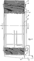
- the dust collector or filter apparatus 10 includes a housing 12 which supports an upper pulley 14 mounted for rotation on a shaft 16, and a lower drive pulley 18 having a drive shaft 20 which can be connected to any convenient drive source, such as a drive motor 21.
- the housing 12 includes an interior frame 22 formed with a closed side wall 24 at one side thereof, and a clean air outlet conduit 26 is formed at the other side portion to permit withdrawal of the clean air, as will be described in greater detail presently.
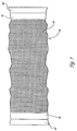
- a filter element 28 is comprised of a flexible substrate 30 having a plurality of openings 32 extending therethrough and a filter media 34 which is in the form of a plurality of inverted U-shaped pleats 34 that, as best seen in Fig. 3, extend outwardly from the surface of the substrate 30 with a spacing between each pleat 34.
- the inverted U-shaped pleats 34 are closed along their outwardly extending length, but the interior of each pleat 34 is open at its connection to the substrate 30.
- the pleats 34 may be formed on the substrate 30 in any satisfactory manner, and in the preferred embodiment of the present invention the filter media 34 has a sinuous configuration that is attached to the substrate in a manner to be described below, a somewhat similar filter media being disclosed in Williams U.S. Patent No. 5,346,519, which is incorporated herein by reference.
- the filter element 28 is an endless belt that is mounted about the upper pulley 14 and the lower drive pulley 18 so as to present two generally parallel straight reaches 36 and two curved reaches 38 at the point where the filter element passes over the pulleys 14,18.
- the pleats 34 extend outwardly from the substrate 30 in generally spaced, parallel relation to one another with a slight spacing therebetween, and these pleats 34, at the curved reaches 38, extend outwardly from the substrate in an open angular relation to one another such that the spacing between adjacent pleats 34 increases along the outwardly extending direction thereof.
- the housing 12 is also provided with a suction nozzle 40 which is positioned adjacent the outer surface of the endless filter element 28 at one of the curved reaches 38 thereof, and, as best seen in Fig. 5, the suction nozzle 40 extends across the entire width of the filter element 28 with one end 42 thereof connected to any convenient source of suction, such as a suction blower 43, and the suction nozzle has a gradually decreasing cross-sectional area along its extending length from the end 42 to generally equalize the suction force imposed on the filter element 28 through a bottom slot 44 (see Fig. 3) of the suction nozzle 40.
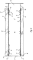
- the outermost side edges 46 of the substrate 30 are imperforate, and the inner surface of these side edges 46 are arranged to slide along flat support surfaces 48 formed on the frame 22.
- the upper surface of the outermost portion 46' of the substrate 30 is formed of a Velcro-type loop material to which the filter media 34 can be attached by forming it with a corresponding Velcro-type hook material, whereby the filter media 34, which must be replaced at periodic intervals, can be easily separated from the more expensive substrate 30 and replaced.
- the flat support surfaces 48 are located on each side of the frame 22, and they extend along the entire vertical height of the dust collector 10, on both sides of the clean air chamber 52, and they have curved portions at the upper and lower ends thereof which are located adjacent the outer edges of the upper pulley 14 and the lower pulley 18 with a radius of curvature corresponding to that of the pulleys 14 and 18, so that the flat support surfaces 48 lie adjacent the outermost side edges of the substrate 30 along its entire generally elliptical extent.
- Each of the support surfaces 48 is shaped to include a suction channel 50 that extends along the length thereof beneath the approximate mid-portion of the imperforate side edges 46 of the substrate 30, and these suction channels 50 may be connected to the same suction source connected to the suction nozzle 40, as illustrated in Fig. 4.
- a quantity of transport air having entrained therein dust, lint, or any other foreign matter is introduced to the dust collector 10 at the exterior thereof, and a pressure differential is created across the filter element 28, preferably by a vacuum being imposed on the interior of the housing 12 through the clean air discharge conduit 26.
- This suction causes the transport air to be drawn through the pleats 34 of the filter element 28 so that foreign matter entrained in the transport air will be deposited on the exterior surfaces of the pleats 34, and the cleaned air will pass through the inverted U-shaped pleats to the interior thereof and through the openings 32 in the substrate 30 so that the cleaned air is collected in a clean air chamber 52 (see Fig. 6) within the housing 12 and can be withdrawn through the clean air discharge conduit 26.
- the endless filter element 28 is continuously moved through its somewhat elliptical path of movement around the pulleys 14,18, and the transport air is drawn through filter element 28 at the two straight reaches 36 thereof, and this foreign matter accumulates on the exterior surfaces of the pleats 34 during the movement of the filter element 28 along these straight reaches 36.
- these pleats 34 reach the lower pulley 18, they proceed through one of the curved reaches 38 and, as best seen in Fig.
- the spacing between the pleats 34 opens significantly so that the area between adjacent pleats 34, and particularly the bottom area of the spacing adjacent the substrate 30, is significantly more exposed, whereby the suction imposed on the filter element 28 by the closely adjacent suction nozzle 40 can more easily reach and withdraw foreign matter which has collected even on the innermost surfaces of the pleats 34.
- one significant feature of the present invention is that the area of the filter media presented by the pleats 34 is substantially greater than the area that would be presented by a typical or conventional belt filter, such as a felt belt, in which the available filtering surface constitutes only the outer flat surface of the belt, which corresponds generally to the flat outer surface of the substrate 30.
- the exposed surface area of each pleat 34 is the area that extends outwardly from the substrate 30 along one of the flat sides of the pleat 34, the small closed end portion of the pleat 34, and the other parallel extending side portion of the pleat 34, and the total area presented to the dirty air is the sum of the surface areas of all of the pleats 34 positioned along each of the two straight reaches 36.
- the ability to clean the foreign matter from the large number of closely spaced pleats 34 is significantly enhanced by the fact that the normally close spacing between adjacent pleats 34 is substantially opened as the pleats 34 pass around the surface of the lower pulley 18, which has a relatively small radius selected to properly open the spacing between adjacent pleats 34, the extent of such opening depending on the particular application of the dust collector 10.
- the cylindrical support surface of the lower pulley 18 is solid and imperforate so that the suction at the interior of the housing 12 does not draw dirty transport air inwardly through the filter element 28 while the pleats 34 are being cleaned by the suction nozzle 40, whereby the suction force applied to the exterior surfaces of the pleats 34 by the suction nozzle 40 is not offset by the flow of the transport air in the opposite direction through the pleats 34.
- a suction force in any desired amount is imposed on the suction channels 50 in the housing 12, and this suction force acts on the imperforate side edges 46 of the substrate 30 to pull the imperforate side edges 46 flush against the flat support surfaces 48 of the frame 22 and thereby seal the clean air chamber 52 and prevent the dirty transport air from passing into the clean air chamber 52 indirectly at the abutment between the moving imperforate side edges 46 and the fixed support surfaces 48.
Landscapes
- Chemical & Material Sciences (AREA)
- Chemical Kinetics & Catalysis (AREA)
- Filtering Of Dispersed Particles In Gases (AREA)
Applications Claiming Priority (2)
| Application Number | Priority Date | Filing Date | Title |
|---|---|---|---|
| US500572 | 1990-03-28 | ||
| US08/500,572 US5560835A (en) | 1995-07-11 | 1995-07-11 | Pleated belt filter with suction means to remove debris |
Publications (3)
| Publication Number | Publication Date |
|---|---|
| EP0753333A2 true EP0753333A2 (de) | 1997-01-15 |
| EP0753333A3 EP0753333A3 (de) | 1997-01-22 |
| EP0753333B1 EP0753333B1 (de) | 1999-11-10 |
Family
ID=23990011
Family Applications (1)
| Application Number | Title | Priority Date | Filing Date |
|---|---|---|---|
| EP96110705A Expired - Lifetime EP0753333B1 (de) | 1995-07-11 | 1996-07-03 | Selbstreinigender Bandfilter und Verfahren |
Country Status (9)
| Country | Link |
|---|---|
| US (1) | US5560835A (de) |
| EP (1) | EP0753333B1 (de) |
| AR (1) | AR002796A1 (de) |
| AT (1) | ATE186472T1 (de) |
| BR (1) | BR9601934A (de) |
| CA (1) | CA2180895C (de) |
| DE (1) | DE69605081T2 (de) |
| ES (1) | ES2138274T3 (de) |
| MX (1) | MX9602717A (de) |
Cited By (1)
| Publication number | Priority date | Publication date | Assignee | Title |
|---|---|---|---|---|
| WO2017076166A1 (zh) * | 2015-11-07 | 2017-05-11 | 深圳市前海安测信息技术有限公司 | 具有自洁净功能的空气过滤设备 |
Families Citing this family (25)
| Publication number | Priority date | Publication date | Assignee | Title |
|---|---|---|---|---|
| US5906752A (en) * | 1995-07-11 | 1999-05-25 | Pneumafil Corporation | Self-cleaning belt filter with edge sealing means and method |
| DE19536444C2 (de) * | 1995-09-29 | 1998-11-26 | Siemens Ag | Verfahren zum Betrieb einer Katalysatoranordnung in ein- oder mehrteiliger Ausbildung, insbesondere für den Einsatz in Rauchgasreinigungsverfahren sowie Katalysatoranordnung zur Durchführung des Verfahrens |
| DE19624483A1 (de) * | 1996-06-19 | 1998-01-02 | Mecana Umwelttechnik Ag | Filtertuch, Filtrierverfahren und Filtriervorrichtung für die Flüssigkeitsfiltration |
| US5730767A (en) * | 1996-07-30 | 1998-03-24 | Pneumafil Corporation | Sealing apparatus in a belt-type filter |
| GB2331027B (en) * | 1997-11-07 | 2000-04-19 | Peter Anthony Miller | A fluid filtering apparatus |
| US6099609A (en) * | 1998-07-30 | 2000-08-08 | 3M Innovative Properties Company | Moving sorbent filter device |
| US6099608A (en) * | 1998-07-30 | 2000-08-08 | 3M Innovative Properties Company | Rotating filtration cartridge and blower for HVAC applications |
| US6277176B1 (en) | 1998-07-30 | 2001-08-21 | 3M Innovative Properties Company | Moving filter device having filter elements with flow passages and method of filtering air |
| DE29909484U1 (de) * | 1999-05-31 | 1999-09-02 | LTA Lufttechnik GmbH, 77787 Nordrach | Vorfilterelement mit Filtervlies |
| CN101400243A (zh) * | 2007-09-26 | 2009-04-01 | 鸿富锦精密工业(深圳)有限公司 | 滤网更换系统 |
| US8617278B2 (en) | 2009-09-16 | 2013-12-31 | Challen Sullivan | Replacement cartridge filter with pleated filter media, automatic filter media advance and wireless communications |
| US8657936B2 (en) * | 2009-09-16 | 2014-02-25 | Challen Sullivan | Direct replacement air filter with automatic filter media advance and wireless communications |
| US8591616B2 (en) | 2009-09-16 | 2013-11-26 | Challen Sullivan | Direct replacement filter with automatic pleated filter media advance |
| US8313567B2 (en) * | 2009-09-16 | 2012-11-20 | Smart Air Filter, LLC | Direct replacement air handler filter with automatic filter media advance |
| US8734641B2 (en) | 2010-09-08 | 2014-05-27 | Anthony Collins | Tertiary wastewater filtration using inclined filter media and internal reverse flow backwashing of filter disks |
| US10905981B2 (en) | 2011-10-28 | 2021-02-02 | Alfa Laval Corporate Ab | Methods and apparatus for treating water and wastewater employing a cloth filter |
| US8852445B2 (en) | 2011-10-28 | 2014-10-07 | Alfa Laval Ashbrook Simon-Hartley, Inc | Methods and apparatus for treating water and wastewater employing a cloth disk filter |
| US8986414B2 (en) | 2012-02-29 | 2015-03-24 | Challen Sullivan | Method of adhering a pleated filtration media and filter and media filter stack using same |
| US9423608B2 (en) | 2012-08-01 | 2016-08-23 | Pentair Water Pool And Spa, Inc. | Multidimensional rotary motion apparatus moving a reflective surface and method of operating same |
| CN106076015B (zh) * | 2016-08-04 | 2018-09-14 | 山东神华山大能源环境有限公司 | 一种过滤面可移动的除尘器 |
| US11529573B2 (en) | 2019-04-23 | 2022-12-20 | Greatpyr Resources Llc | Systems and processes employing wet/dry suction filter |
| KR102183820B1 (ko) * | 2020-03-10 | 2020-11-30 | 주식회사 그레넥스 | 섬유상 여과기의 역세정 흡입장치 |
| KR102588387B1 (ko) * | 2021-02-17 | 2023-10-11 | 현대트랜시스 주식회사 | 차량용 시트의 공조 어셈블리 |
| US12377372B2 (en) | 2021-06-08 | 2025-08-05 | Greatpyr Resources Llc | Apparatus, systems, and processes employing wet/dry suction filter with chicaned suction head |
| US12246272B2 (en) | 2021-11-04 | 2025-03-11 | Thomas E. Frankel | Wastewater filters and wastewater filtration systems specifically adapted for their use |
Family Cites Families (15)
| Publication number | Priority date | Publication date | Assignee | Title |
|---|---|---|---|---|
| GB743876A (de) * | 1900-01-01 | |||
| GB191003571A (en) * | 1910-02-14 | 1911-02-14 | Frederick Mills Hotblack | Improvements in Apparatus for Purifying Air. |
| US2335144A (en) * | 1942-03-06 | 1943-11-23 | American Air Filter Co | Dry filter |
| US2463723A (en) * | 1944-11-28 | 1949-03-08 | Spraragen Louis | Air filter |
| GB700352A (en) * | 1950-04-26 | 1953-12-02 | Eric Victor Giles | Improvements in or relating to the separation of dust from air or other gases |
| US4153008A (en) * | 1977-04-07 | 1979-05-08 | Interrad Corporation | Moving filter system for air-powder separation in an electrostatic powder spray system |
| US4187091A (en) * | 1977-05-16 | 1980-02-05 | Donaldson Company, Inc. | Pleated paper filter cartridge |
| US4257345A (en) * | 1978-09-21 | 1981-03-24 | Westinghouse Electric Corp. | Electrostatic powder coating installation |
| DE3222199C2 (de) * | 1982-06-12 | 1986-09-25 | Herbert Kannegiesser Gmbh + Co, 4973 Vlotho | Vorrichtung zum Glätten von Kleidungsstücken |
| FR2544219B1 (fr) * | 1983-04-14 | 1985-08-16 | Queyroix Christian | Filtre horizontal a bande sans fin sous vide |
| US4725292A (en) * | 1984-02-10 | 1988-02-16 | Pneumafil Corporation | Self-cleaning filter |
| US4875913A (en) * | 1984-05-24 | 1989-10-24 | Filtration Water Filters For Agriculture And Industry, Ltd. | Apparatus for cleaning corrugated filter elements |
| US4772398A (en) * | 1986-02-13 | 1988-09-20 | Sando Iron Works Co., Ltd. | Method for treatment of waste water and its apparatus |
| US4842749A (en) * | 1988-09-30 | 1989-06-27 | Cox Clyde H | Inversion tube press |
| US5346519A (en) * | 1993-04-27 | 1994-09-13 | Pneumafil Corporation | Filter media construction |
-
1995
- 1995-07-11 US US08/500,572 patent/US5560835A/en not_active Expired - Lifetime
-
1996
- 1996-07-03 ES ES96110705T patent/ES2138274T3/es not_active Expired - Lifetime
- 1996-07-03 EP EP96110705A patent/EP0753333B1/de not_active Expired - Lifetime
- 1996-07-03 DE DE69605081T patent/DE69605081T2/de not_active Expired - Fee Related
- 1996-07-03 AT AT96110705T patent/ATE186472T1/de active
- 1996-07-10 BR BR9601934A patent/BR9601934A/pt not_active IP Right Cessation
- 1996-07-10 AR ARP960103518A patent/AR002796A1/es unknown
- 1996-07-10 CA CA002180895A patent/CA2180895C/en not_active Expired - Fee Related
- 1996-07-10 MX MX9602717A patent/MX9602717A/es not_active IP Right Cessation
Cited By (1)
| Publication number | Priority date | Publication date | Assignee | Title |
|---|---|---|---|---|
| WO2017076166A1 (zh) * | 2015-11-07 | 2017-05-11 | 深圳市前海安测信息技术有限公司 | 具有自洁净功能的空气过滤设备 |
Also Published As
| Publication number | Publication date |
|---|---|
| AR002796A1 (es) | 1998-04-29 |
| US5560835A (en) | 1996-10-01 |
| BR9601934A (pt) | 1998-09-29 |
| MX9602717A (es) | 1997-01-31 |
| CA2180895C (en) | 1999-10-19 |
| DE69605081D1 (de) | 1999-12-16 |
| ATE186472T1 (de) | 1999-11-15 |
| EP0753333A3 (de) | 1997-01-22 |
| ES2138274T3 (es) | 2000-01-01 |
| EP0753333B1 (de) | 1999-11-10 |
| CA2180895A1 (en) | 1997-01-12 |
| DE69605081T2 (de) | 2000-04-27 |
Similar Documents
| Publication | Publication Date | Title |
|---|---|---|
| US5560835A (en) | Pleated belt filter with suction means to remove debris | |
| EP0080616B1 (de) | Gasfiltrationsverfahren für Schwebeteilchen | |
| CA2211840C (en) | Self-cleaning belt filter and method | |
| KR830001386B1 (ko) | 여과기백 지지장치를 겸한 공기확산기를 가지고 있는 백형여과장치 | |
| US5882528A (en) | Method for extending useful life of filter aid in a filter with hydraulically deformable system | |
| US5624579A (en) | Method of simultaneously indexing permanent and disposable filter media in a vacuum filter apparatus | |
| EP0026069B1 (de) | Vorrichtung und Verfahren zur Abscheidung feinzerteilter Materialien aus einem flüssigen Medium | |
| RU2271852C2 (ru) | Способ и устройство для отделения жидкостей от твердых веществ, снабженное средствами для отбора жидкости снизу и по бокам сквозь транспортерную ленту | |
| US4394146A (en) | Filter apparatus | |
| US4360369A (en) | Apparatus for filtering particulates from a fluid | |
| MXPA97005782A (en) | Self cleaning and met band filter | |
| EP0210164B1 (de) | Filter, insbesondere luftfilter | |
| JPS645934B2 (de) | ||
| US4427422A (en) | Method for filtering particulates from a fluid | |
| CA2313871C (en) | Self-cleaning belt filter and method | |
| WO2002020124A1 (en) | Filter | |
| DK1838406T3 (en) | Folded air filter with opposite impulse air flow cleaning | |
| CA2211843C (en) | Sealing apparatus and method for use in a belt-type filter | |
| EP0020101A1 (de) | Vakuum-Bandfilter mit Vakuumabdichtungen | |
| EP0075403A1 (de) | Verfahren und Vorrichtung zur Entfernung einer Filterschicht unter Mitwirkung einer Strömung | |
| JPS5932917A (ja) | 内部収集濾過用バツグの効率増進方法とその装置 | |
| US4470913A (en) | Method and apparatus for fluid assisted filter doffing | |
| JPS60248217A (ja) | ろ過用媒体の清浄方法及び自己清浄フィルタ装置 | |
| US4568368A (en) | Electrostatic powder coating apparatus | |
| MXPA97005781A (en) | Apparatus and sealing method for use in unit of type ba |
Legal Events
| Date | Code | Title | Description |
|---|---|---|---|
| PUAI | Public reference made under article 153(3) epc to a published international application that has entered the european phase |
Free format text: ORIGINAL CODE: 0009012 |
|
| PUAL | Search report despatched |
Free format text: ORIGINAL CODE: 0009013 |
|
| AK | Designated contracting states |
Kind code of ref document: A2 Designated state(s): AT BE CH DE DK ES FI FR GB GR IE IT LI LU MC NL PT SE |
|
| AK | Designated contracting states |
Kind code of ref document: A3 Designated state(s): AT BE CH DE DK ES FI FR GB GR IE IT LI LU MC NL PT SE |
|
| 17P | Request for examination filed |
Effective date: 19970312 |
|
| 17Q | First examination report despatched |
Effective date: 19971211 |
|
| GRAG | Despatch of communication of intention to grant |
Free format text: ORIGINAL CODE: EPIDOS AGRA |
|
| GRAG | Despatch of communication of intention to grant |
Free format text: ORIGINAL CODE: EPIDOS AGRA |
|
| GRAH | Despatch of communication of intention to grant a patent |
Free format text: ORIGINAL CODE: EPIDOS IGRA |
|
| GRAH | Despatch of communication of intention to grant a patent |
Free format text: ORIGINAL CODE: EPIDOS IGRA |
|
| GRAA | (expected) grant |
Free format text: ORIGINAL CODE: 0009210 |
|
| AK | Designated contracting states |
Kind code of ref document: B1 Designated state(s): AT BE CH DE DK ES FI FR GB GR IE IT LI LU MC NL PT SE |
|
| PG25 | Lapsed in a contracting state [announced via postgrant information from national office to epo] |
Ref country code: GR Free format text: LAPSE BECAUSE OF NON-PAYMENT OF DUE FEES Effective date: 19991110 Ref country code: FI Free format text: LAPSE BECAUSE OF NON-PAYMENT OF DUE FEES Effective date: 19991110 Ref country code: BE Free format text: LAPSE BECAUSE OF FAILURE TO SUBMIT A TRANSLATION OF THE DESCRIPTION OR TO PAY THE FEE WITHIN THE PRESCRIBED TIME-LIMIT Effective date: 19991110 Ref country code: AT Free format text: LAPSE BECAUSE OF FAILURE TO SUBMIT A TRANSLATION OF THE DESCRIPTION OR TO PAY THE FEE WITHIN THE PRESCRIBED TIME-LIMIT Effective date: 19991110 |
|
| REF | Corresponds to: |
Ref document number: 186472 Country of ref document: AT Date of ref document: 19991115 Kind code of ref document: T |
|
| REG | Reference to a national code |
Ref country code: CH Ref legal event code: EP |
|
| ITF | It: translation for a ep patent filed | ||
| REF | Corresponds to: |
Ref document number: 69605081 Country of ref document: DE Date of ref document: 19991216 |
|
| REG | Reference to a national code |
Ref country code: CH Ref legal event code: NV Representative=s name: PATENTANWALTSBUERO G. PETSCHNER |
|
| REG | Reference to a national code |
Ref country code: ES Ref legal event code: FG2A Ref document number: 2138274 Country of ref document: ES Kind code of ref document: T3 |
|
| REG | Reference to a national code |
Ref country code: IE Ref legal event code: FG4D |
|
| PG25 | Lapsed in a contracting state [announced via postgrant information from national office to epo] |
Ref country code: DK Free format text: LAPSE BECAUSE OF FAILURE TO SUBMIT A TRANSLATION OF THE DESCRIPTION OR TO PAY THE FEE WITHIN THE PRESCRIBED TIME-LIMIT Effective date: 20000210 |
|
| REG | Reference to a national code |
Ref country code: PT Ref legal event code: SC4A Free format text: AVAILABILITY OF NATIONAL TRANSLATION Effective date: 19991207 |
|
| ET | Fr: translation filed | ||
| PG25 | Lapsed in a contracting state [announced via postgrant information from national office to epo] |
Ref country code: LU Free format text: LAPSE BECAUSE OF NON-PAYMENT OF DUE FEES Effective date: 20000703 |
|
| PG25 | Lapsed in a contracting state [announced via postgrant information from national office to epo] |
Ref country code: MC Free format text: THE PATENT HAS BEEN ANNULLED BY A DECISION OF A NATIONAL AUTHORITY Effective date: 20000731 |
|
| PLBE | No opposition filed within time limit |
Free format text: ORIGINAL CODE: 0009261 |
|
| STAA | Information on the status of an ep patent application or granted ep patent |
Free format text: STATUS: NO OPPOSITION FILED WITHIN TIME LIMIT |
|
| 26N | No opposition filed | ||
| REG | Reference to a national code |
Ref country code: GB Ref legal event code: IF02 |
|
| REG | Reference to a national code |
Ref country code: CH Ref legal event code: NV Representative=s name: ZIMMERLI, WAGNER & PARTNER AG |
|
| PGFP | Annual fee paid to national office [announced via postgrant information from national office to epo] |
Ref country code: PT Payment date: 20080620 Year of fee payment: 13 |
|
| PGFP | Annual fee paid to national office [announced via postgrant information from national office to epo] |
Ref country code: ES Payment date: 20080728 Year of fee payment: 13 Ref country code: DE Payment date: 20080829 Year of fee payment: 13 Ref country code: CH Payment date: 20080730 Year of fee payment: 13 |
|
| PGFP | Annual fee paid to national office [announced via postgrant information from national office to epo] |
Ref country code: NL Payment date: 20080724 Year of fee payment: 13 Ref country code: IT Payment date: 20080726 Year of fee payment: 13 Ref country code: IE Payment date: 20080725 Year of fee payment: 13 Ref country code: FR Payment date: 20080729 Year of fee payment: 13 |
|
| PGFP | Annual fee paid to national office [announced via postgrant information from national office to epo] |
Ref country code: GB Payment date: 20080729 Year of fee payment: 13 |
|
| PGFP | Annual fee paid to national office [announced via postgrant information from national office to epo] |
Ref country code: SE Payment date: 20080729 Year of fee payment: 13 |
|
| REG | Reference to a national code |
Ref country code: CH Ref legal event code: PFA Owner name: PNEUMAFIL CORPORATION Free format text: PNEUMAFIL CORPORATION#4404-B CHESAPEAKE DRIVE,P.O. BOX 16348#CHARLOTTE, NORTH CAROLINA 28297 (US) -TRANSFER TO- PNEUMAFIL CORPORATION#4404-B CHESAPEAKE DRIVE,P.O. BOX 16348#CHARLOTTE, NORTH CAROLINA 28297 (US) |
|
| REG | Reference to a national code |
Ref country code: PT Ref legal event code: MM4A Free format text: LAPSE DUE TO NON-PAYMENT OF FEES Effective date: 20100104 |
|
| REG | Reference to a national code |
Ref country code: CH Ref legal event code: PL |
|
| EUG | Se: european patent has lapsed | ||
| GBPC | Gb: european patent ceased through non-payment of renewal fee |
Effective date: 20090703 |
|
| NLV4 | Nl: lapsed or anulled due to non-payment of the annual fee |
Effective date: 20100201 |
|
| REG | Reference to a national code |
Ref country code: FR Ref legal event code: ST Effective date: 20100331 |
|
| REG | Reference to a national code |
Ref country code: IE Ref legal event code: MM4A |
|
| PG25 | Lapsed in a contracting state [announced via postgrant information from national office to epo] |
Ref country code: PT Free format text: LAPSE BECAUSE OF NON-PAYMENT OF DUE FEES Effective date: 20100104 Ref country code: LI Free format text: LAPSE BECAUSE OF NON-PAYMENT OF DUE FEES Effective date: 20090731 Ref country code: FR Free format text: LAPSE BECAUSE OF NON-PAYMENT OF DUE FEES Effective date: 20090731 Ref country code: CH Free format text: LAPSE BECAUSE OF NON-PAYMENT OF DUE FEES Effective date: 20090731 |
|
| PG25 | Lapsed in a contracting state [announced via postgrant information from national office to epo] |
Ref country code: GB Free format text: LAPSE BECAUSE OF NON-PAYMENT OF DUE FEES Effective date: 20090703 |
|
| PG25 | Lapsed in a contracting state [announced via postgrant information from national office to epo] |
Ref country code: DE Free format text: LAPSE BECAUSE OF NON-PAYMENT OF DUE FEES Effective date: 20100202 |
|
| PG25 | Lapsed in a contracting state [announced via postgrant information from national office to epo] |
Ref country code: IE Free format text: LAPSE BECAUSE OF NON-PAYMENT OF DUE FEES Effective date: 20090703 |
|
| REG | Reference to a national code |
Ref country code: ES Ref legal event code: FD2A Effective date: 20090704 |
|
| PG25 | Lapsed in a contracting state [announced via postgrant information from national office to epo] |
Ref country code: ES Free format text: LAPSE BECAUSE OF NON-PAYMENT OF DUE FEES Effective date: 20090704 |
|
| PG25 | Lapsed in a contracting state [announced via postgrant information from national office to epo] |
Ref country code: IT Free format text: LAPSE BECAUSE OF NON-PAYMENT OF DUE FEES Effective date: 20090703 |
|
| PG25 | Lapsed in a contracting state [announced via postgrant information from national office to epo] |
Ref country code: SE Free format text: LAPSE BECAUSE OF NON-PAYMENT OF DUE FEES Effective date: 20090704 |
|
| PG25 | Lapsed in a contracting state [announced via postgrant information from national office to epo] |
Ref country code: NL Free format text: LAPSE BECAUSE OF NON-PAYMENT OF DUE FEES Effective date: 20100201 |