EP0753236B1 - Methode und vorrichtung zur dynamischen reinheitskorrektur - Google Patents
Methode und vorrichtung zur dynamischen reinheitskorrektur Download PDFInfo
- Publication number
- EP0753236B1 EP0753236B1 EP95914828A EP95914828A EP0753236B1 EP 0753236 B1 EP0753236 B1 EP 0753236B1 EP 95914828 A EP95914828 A EP 95914828A EP 95914828 A EP95914828 A EP 95914828A EP 0753236 B1 EP0753236 B1 EP 0753236B1
- Authority
- EP
- European Patent Office
- Prior art keywords
- values
- monitor
- luminescence
- correction
- interpolating
- Prior art date
- Legal status (The legal status is an assumption and is not a legal conclusion. Google has not performed a legal analysis and makes no representation as to the accuracy of the status listed.)
- Expired - Lifetime
Links
Images


Classifications
-
- H—ELECTRICITY
- H04—ELECTRIC COMMUNICATION TECHNIQUE
- H04N—PICTORIAL COMMUNICATION, e.g. TELEVISION
- H04N9/00—Details of colour television systems
- H04N9/64—Circuits for processing colour signals
- H04N9/68—Circuits for processing colour signals for controlling the amplitude of colour signals, e.g. automatic chroma control circuits
- H04N9/69—Circuits for processing colour signals for controlling the amplitude of colour signals, e.g. automatic chroma control circuits for modifying the colour signals by gamma correction
-
- H—ELECTRICITY
- H04—ELECTRIC COMMUNICATION TECHNIQUE
- H04N—PICTORIAL COMMUNICATION, e.g. TELEVISION
- H04N9/00—Details of colour television systems
- H04N9/64—Circuits for processing colour signals
- H04N9/68—Circuits for processing colour signals for controlling the amplitude of colour signals, e.g. automatic chroma control circuits
-
- H—ELECTRICITY
- H04—ELECTRIC COMMUNICATION TECHNIQUE
- H04N—PICTORIAL COMMUNICATION, e.g. TELEVISION
- H04N17/00—Diagnosis, testing or measuring for television systems or their details
- H04N17/02—Diagnosis, testing or measuring for television systems or their details for colour television signals
-
- H—ELECTRICITY
- H04—ELECTRIC COMMUNICATION TECHNIQUE
- H04N—PICTORIAL COMMUNICATION, e.g. TELEVISION
- H04N17/00—Diagnosis, testing or measuring for television systems or their details
- H04N17/04—Diagnosis, testing or measuring for television systems or their details for receivers
-
- H—ELECTRICITY
- H04—ELECTRIC COMMUNICATION TECHNIQUE
- H04N—PICTORIAL COMMUNICATION, e.g. TELEVISION
- H04N9/00—Details of colour television systems
- H04N9/64—Circuits for processing colour signals
- H04N9/73—Colour balance circuits, e.g. white balance circuits or colour temperature control
-
- H—ELECTRICITY
- H04—ELECTRIC COMMUNICATION TECHNIQUE
- H04N—PICTORIAL COMMUNICATION, e.g. TELEVISION
- H04N9/00—Details of colour television systems
- H04N9/77—Circuits for processing the brightness signal and the chrominance signal relative to each other, e.g. adjusting the phase of the brightness signal relative to the colour signal, correcting differential gain or differential phase
Definitions
- the invention pertains to a method of improving the color accuracy of a monitor by compensating for the luminance variations that occur across the face of the monitor by computing and then applying smoothly varying correction values to each color component of each pixel in real time.
- Monitors have been increasingly used in photorealistic color production and prepress systems. Accordingly, it is important that any luminance variations across the face of the monitor be corrected in order to insure color accuracy and predictability. If luminance differences exist between color channels, then color purity will be compromised.
- Luminance variations can be introduced into a monitor by a number of ways including, but not limited to, aging, shock, non-uniformities in phosphor deposition, shadow mask imperfections or thermal changes, differences in the beam energies of the different electron guns, and the position of the monitor relative to earth's magnetic field.
- the variations so introduced must be compensated for and corrected to maintain high color purity and uniformity.
- US-4,962,418 describes a color picture display apparatus for monitoring and correcting display colors of a picture picked up by a camera (e.g. an endoscope) and displayed on a display.
- a camera e.g. an endoscope
- this apparatus integrally monitors the display solely yielding one mean gamma characteristics of the display.
- European Patent Application Publication No. 514 025 A2 by Rasterops Corporation discloses the use of a video normalizer to correct irregularities in video display monitor screens.
- a photosensor detects the light output at various points on the monitor. These output values are converted to digital signals and processed to compute correction values. The correction values are then provided to a separate frame buffer that is external to the computer having a memory location for each pixel on the monitor display.
- a correction circuit converts these digital signals into analog correction signals which in turn either skew the Output signals of the video color processing board or control transconductance amplifiers connected between the video color processing board and the RGB inputs of the monitor. This method has some problems in terms of speed.
- the present inventor has recognized that a preferable system would be able to rapidly calculate and apply smoothly varying correction signals in the digital domain on a pixel by pixel basis, for each color component, and that it would be advantageous for such a system to continuously calculate correction values for each pixel in real time (at the display dot clock rate) to avoid having to continuously store and retrieve these values.
- the present invention it had not been known how to overcome the limitations of the described prior art, or how to implement the described improvements over the prior art.
- the present invention provides a method for dynamically adjusting the luminance of each color channel digitally in real time. This "on the fly” approach reduces the complexity and enhances the speed and fidelity of dynamic purity correction, where "dynamic purity correction” denotes the process of determining correction values for each color component of each pixel of a monitor and multiplying incoming digital video signals by these correction values so that the resulting images accurately represent the information contained in the incoming signals.
- three separate correction data streams are generated by processing a regular grid of luminosity sample points (one for each color component, typically from the set of red (R), green (G), and blue(B) color components) by interpolating Catmull-Rom splines, and then multiplying the incoming color (typically RGB) components of each pixel of an input image data stream by the corresponding correction factor.
- FIG. 1 A system employing an embodiment of the present invention is shown in Figure 1. Although the technique is described in relation to a color monitor, the same technique can be used to improve the display accuracy of a monochrome monitor.
- Red, Green and Blue (RGB) luminosity components are measured at each of a plurality of measurement points across the face of a monitor 100. These luminosity values can be measured via a sensor 150, which measures, in the case of an RGB monitor, a red value (R), a blue value (B), and a green value (G) at a grid of regularly spaced points on the face of monitor 100. The sensor then supplies these values to a correction value calculation circuit (CVCC) 200.
- CVCC correction value calculation circuit
- These luminosity values are processed in the CVCC 200, where a correction value is calculated for each color component of each individual pixel. For example, for an RGB color monitor, correction values Cr, Cg, or Cb would be calculated for the corresponding red (R), green (G), and blue (B) components of each pixel.
- Digital video signals, coming from block 300, whose color component signals are represented as R, G and B, are input to Color Lookup Tables (LUT) 350a,b,c, the resulting outputs Ri, Gi, and Bi of the LUTs are corrected to compensate for any detected luminosity variations that exist across the face of the monitor.
- the resulting corrected signals Ri', Gi' and Bi' are fed to monitor 100 after being converted to analog values by digital to analog converters (DACs) 155a,155b,155c.
- DACs digital to analog converters
- the CVCC 200 is detailed in Figure 2.
- the luminosity values measured by sensor 150 are supplied to a computer 210 which generates from the measured luminosity values a regular grid of luminosity values suitable for interpolating via Catmull-Rom splines a correction surface equal in size to that of the display.
- Each vertically (Y) direction aligned set of luminosity measurements is then interpolated into a smooth curve by the computer 210.
- these curves are also generated by interpolating Catmull-Rom splines where each interpolated point on a curve is separated in the Y direction from its neighbors by one pixel. These curves are stored in local VRAM 220 to be retrieved as control points during the raster scan of the image.
- a set of control points one point from each of the vertically interpolated curves, is retrieved from the VRAM and supplied to the Catmull-Rom spline interpolator 230.
- the interpolator computes a smooth Catmull-Rom spline of correction values in the horizontal (X) direction on the fly through the control points for each color component, and these correction values (shown as Cr, Cg, and Cb) are subsequently multiplied by the incoming digital video signals as shown in Figure 2.
- the corrected color components are then gamma corrected 240 to compensate for monitor gamma, which is a function of signal amplitude, and emerge from the correction value calculation circuit as Ri', Gi', and Bi' in Figure 2.
- smooth correction surfaces are derived by interpolating Catmull-Rom splines through luminosity sample points for each corresponding color component, first in the vertical (Y) direction by a computer, and then in the horizontal (X) direction in real time as the image is raster scanned.
- Catmull-Rom splines are a class of splines where the spline actually passes through (interpolates) the sample (control) points. Furthermore, the slope of the spline as it passes through a control point is equal to the slope formed by drawing a line through the control points on either side of the control point being interpolated. This results in a smooth, well behaved curve.
- An example of a Catmull-Rom spline, which passes through four control points, is shown in Figure 3. Four control points (Pi-3, Pi-2, Pi-1, and Pi) are required to interpolate the spline between the points Pi-2 and Pi-1. This section of the spline between points Pi-2 and Pi-1 is called a polynomial segment.
- Catmull-Rom splines are a class of parametric cubic curves. That is, both dimensional components (luminosity (L), and X, where X represents a location on the face of the monitor) of the curve are parameters of some third independent variable, t.
- the curve is approximated by a piecewise polynomial curve that is described by cubic polynomials that are parametric in t.
- t should be chosen such that each step of t corresponds to a one pixel move across (or down) the display. If the control points are regularly spaced in the X axis, then x changes linearly in t. Hence, if the control points are 128 pixels apart, then stepping t 1/128 will result in stepping x one pixel. Therefore x can be ignored as a parametric function of t.
- the interpolated spline can have values greater than the maximum control point values.
- the luminosity values just to the left of Pi-2 are greater than Pi-2 (which is necessarily the case with a smooth curve because the slope of the curve at point Pi-2 is decreasing), hence some "headroom" has to be accounted for when providing the control points to the spline interpolation hardware if overflow is to be avoided.
- a regularly spaced grid of luminosity measurements is taken for each color component.
- the measurements are made 128 pixels apart, by a sensor such as sensor 150 in Figure 1.
- sensor 150 For a 72 dpi monitor this works out to a spacing between measurements of about 1.75".
- An example of such a grid for a 1280 x 1024 display with 63 measurement points is shown in Figure 6.
- a luminosity value grid of 143 points is formed (for each color component) from the measurement grid of Figure 6 to create the interpolated RGB luminosity value grid shown in Figure 7.
- the additional interpolated points both on and outside the boundary of the visible display area in Figure 6 can be extrapolated from the measured points by a variety of techniques. In the preferred embodiment, some of the points are made by duplicating points near the boundary of the measured grid, and some are made by linearly interpolating the slope formed by the points near the boundary of the measured grid.
- the entire 3-dimensional correction surface is computed on computer 210 using the interpolated RGB luminosity value grid shown in Figure 7, and all the luminosity values are uniformly adjusted such that no point on the surface exceeds, or overflows, a maximum value.
- sensor 150 One way of arriving at the grid of measured RGB luminosity values would be to implement sensor 150 as a jig having an array of photometers being placed across the face of the monitor. This array of photometers would be used to measure the screen RGB luminosity data shown in Figure 6.
- the precomputed control points are loaded from VRAM 220 into the Catmull-Rom spline interpolator 230 prior to the start of the scan.
- the control points (or Pi's) for each scanline are loaded from VRAM 220 into the Control Point RAMs 231a,b,c as shown in Figure 5, prior to the start of the scanline.
- the Forward Difference Coefficients (D,C,B,A) for polynomial segment N+1 are precomputed on the fly by the Forward Difference Coefficient Generators 232a,b,c as polynomial segment N is interpolated.
- the forward difference engines 233a,b,c compute the resulting correction values (shown as Cr,Cg,Cb in Figure 5) by evaluating equations 3-6 to find L.
- Kc-1 0x000041fd
- Kc 0xfffff81
- Kb-3 0x000001fa
- Kb-2 0xfffffb12
- Kb-1 0x000003ee
- Kb 0xfffff06
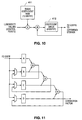
- FIG. 9 A block diagram of the data flow of a RAMDAC monolithic integrated circuit of a preferred embodiment of the present invention is shown in Figure 9.
- the Control Point RAMs 400a,b,c and Forward Difference Coefficient Generators 410a,b,c and Forward Difference Engines 420a,b,c correspond to CVCC 200 of Figure 1 and is detailed in Figure 2.
- Each of the three Control Point RAMs 400a,b,c can contain 18 control points, which will support a display that is 1920 pixels wide.
- Luminosity Control Points For a 1920 x 1030 display, there are 18 x 3 x 1030 or 55,620 Luminosity Control Points (Pi's) to be stored in VRAM. If two bytes of storage are used for each Luminosity Control Point, then this represents approximately a 1.9% memory storage overhead for 24 bit color as compared to the storage requirements for the image itself.
- the correction values are combined with the outputs of the color lookup tables (LUTs) in multipliers 440a,b,c (where these multipliers correspond to multipliers 250a,b,c of Figure 2).
- the outputs of the multipliers are gamma corrected in the Inverse Gamma Correction circuits 450a,b,c to produce corrected values Ri', Gi', and Bi'. These corrected values are then converted into analog signals by digital-to-analog converters 460a,b,c.
- the logic in the Forward Difference Coefficient Generators 420a,b,c of Figure 9 is shown in Figure 10.
- the luminosity values are combined with a Basis Coefficient ROM 411, containing Basis Coefficients. These Basis Coefficients are preferably directly wired into the datapath.
- the Coefficient Queue 412 holds intermediate results (multiply-accumulate) of each coefficient calculation, and stores the coefficients until they can be transferred to the Forward Difference Stepper at the end of the current polynomial segment.
- the radix point for register D is shown 10 bits to the right of the MSB. This is because in simulations to verify the operation of the invention, actual visible correction surfaces were generated from luminosity data, rather than corrections to actual images. In the preferred embodiment, the radix point would be to the left of the MSB, and the upper fractional 10 bits would be sent to the multiplier to modify the incoming pixel color component.
- the 2.5% case would require approximately 4 times the on-board RAM over the alternate approach. More importantly, 4 times more storage would be required in VRAM for the coefficients, which is too much.
Landscapes
- Engineering & Computer Science (AREA)
- Multimedia (AREA)
- Signal Processing (AREA)
- Health & Medical Sciences (AREA)
- Biomedical Technology (AREA)
- General Health & Medical Sciences (AREA)
- Processing Of Color Television Signals (AREA)
- Organic Low-Molecular-Weight Compounds And Preparation Thereof (AREA)
- Manufacture And Refinement Of Metals (AREA)
- Controls And Circuits For Display Device (AREA)
- Video Image Reproduction Devices For Color Tv Systems (AREA)
- Facsimile Image Signal Circuits (AREA)
- Analysing Materials By The Use Of Radiation (AREA)
Claims (23)
- Verfahren zum Ausführen einer dynamischen Reinheitskorrektur für einen Monitor (100), wobei der Monitor (100) eine Sichtfläche aufweist und in der Lage ist, Y Zeilen und X Spalten von Pixeln auf der Sichtfläche anzuzeigen, wobei jeder Pixel einen Helligkeitswert für jede von dem Monitor angezeigte Farbkomponente (R, G, B) aufweist,
gekennzeichnet durch:Messen des Helligkeitswertes für jede Farbkomponente für ein Gitter aus Pixeln auf der Sichtfläche des Monitors, wodurch ein erstes Gitter aus Helligkeitswerten gebildet wird, und Bereitstellen des ersten Gitters aus Helligkeitswerten an einer Berechnungsschaltung für Korrekturwerte (200, CVCC) ;Erzeugen eines zweiten Gitters von Helligkeitswerten aus dem ersten Gitter von Helligkeitswerten, welches für eine nachfolgende Interpolation geeignet ist, wobei das zweite Gitter von Helligkeitswerten vertikal ausgerichtete Sätze von Helligkeitswerten aufweist;Interpolieren jedes vertikal ausgerichteten Satzes von Helligkeitswerten des zweiten Gitters für jede Farbkomponente (R, G, B), um Regelpunkte (Pi) zu berechnen, wobei die Regelpunkte eine Regelpunktmatrix mit Y Zeilen und N Spalten bilden, wobei N eine ganze Zahl kleiner X ist, und wobei die Matrix aus Regelpunkten (Pi) danach in einem Speicher (220) gespeichert wird;Auslesen einer Zeile von N in dem Speicher gespeicherten Regelpunkten (Pi) in einen Interpolator (230) ;Interpolieren jeder Zeile von N aus dem Speicher (220) ausgelesenen Regelpunkten (Pi), um eine entsprechende Zeile aus X Korrekturwerten (Cr, Cg, Cb) zu berechnen;Multiplizieren jeder Zeile von Korrekturwerten (Cr, Cg, Cb) mit einer entsprechenden Zeile von Helligkeitswerten eines eingehenden Videosignals, um für jede Farbkomponente (R, G, B) jedes Pixels der entsprechenden Zeile von Helligkeitswerten einen Satz von Zeilen modifizierter Helligkeitswerte zu erzeugen; undAnzeigen der Zeilen modifizierter Pixel auf dem Monitor (100). - Verfahren nach Anspruch 1,
bei welchem der Monitor (100) drei Farbkomponenten (R, G, B) anzeigt, wobei die drei Farbkomponenten Rot (R), Grün (G) und Blau (B) sind. - Verfahren nach Anspruch 1 oder 2,
bei welchem der Schritt des Messens der Helligkeitswerte unter Verwendung einer Vorrichtung mit einer Matrix aus Fotometern erfolgt. - Verfahren nach einem der Ansprüche 1 bis 3,
bei welchem der Schritt des Interpolierens jedes vertikal ausgerichteten Satzes von Helligkeitswerten und der Schritt des Interpolierens jeder Zeile aus N Regelpunkten (Pi) beide unter Verwendung eines kubischen Polynoms (L(t), X(t)) erfolgen. - Verfahren nach Anspruch 4,
bei welchem das kubische Polynom ein Catmull-Rom Spline (L(t), X(t)) ist. - Verfahren nach einem der Ansprüche 1 bis 5,
welches ferner einen zusätzlichen Schritt beinhaltet, der nach dem Schritt des Multiplizierens, aber vor dem Schritt des Anzeigens erfolgt, wobei der zusätzliche Schritt das Ausführen einer Gammakorrektur für die modifizierten Helligkeitswerte umfasst. - Verfahren nach einem der Ansprüche 1 bis 6,
bei welchem der Schritt des Interpolierens jeder Zeile aus N Regelpunkten und des Multiplizierens jeder Zeile von Korrekturwerten mit den Helligkeitswerten des eingehenden Signals ausgeführt wird, während die entsprechende Zeile von Helligkeitswerten des eingehenden Signals rasterabgetastet wird. - Verfahren nach einem der Ansprüche 5 bis 7,
bei welchem das Catmull-Rom-Spline (L(t), X(t)) unter Verwendung von Vorwärtsdifferenzen berechnet wird, was Verschiebungsschritte und Additionsschritte beinhaltet. - Verfahren nach einem der Ansprüche 1 bis 8,
bei welchem die CVCC (200) einen Rechnerspeicher (220) beinhaltet, um die Helligkeitswerte zu speichern, die diesem nach dem Schritt des Messens zur Verfügung gestellt werden. - Verfahren nach einem der Ansprüche 1 bis 9,
bei welchem der Schritt des Multiplizierens jeder vollständigen Zeile von Korrekturwerten mit einer entsprechenden Zeile von Helligkeitswerten eines eingehenden Videosignals digital erfolgt. - Vorrichtung zum Ausführung einer dynamischen Reinheitskorrektur für einen Monitor (100), wobei der Monitor (100) eine Vielzahl von Pixeln anzeigt, wobei jeder Pixel einen Helligkeitswert für jede von dem Monitor angezeigte Farbkomponente (R, G, B) aufweist,
gekennzeichnet durch:eine Messeinrichtung (150) zum Messen des Helligkeitswertes für jede Farbkomponente (R, G, B) von vorgegebenen Pixeln der durch den Monitor (100) angezeigten Pixel; undeine Einrichtung mit einer Berechnungsschaltung für Korrekturwerte (200, CVCC), welche mit der Messeinrichtung (150) gekoppelt ist, um Korrekturwerte (Cr, Cg, Cb) für jeden der durch den Monitor 100 angezeigten Pixel zu berechnen, basierend auf den von der Messeinrichtung (150) für jede Farbkomponente (R, G, B) gemessenen Helligkeitswerten, wobei die CVCC-Einrichtung (200) außerdem eingehende Videosignale empfängt und diese Signale entsprechend den berechneten Korrekturwerten (Cr, Cg, Cb) modifiziert und die Signale, nachdem sie modifiziert worden sind, an den Monitor sendet, und wobei die CVCC-Einrichtung (200) ferner umfasst:eine Einrichtung zum Speichern der Helligkeitswerte in einen Rechnerspeicher (220) als einen ersten Satz von Gittern; undeine Einrichtung (230) zum Interpolieren der Helligkeitswerte, um die Korrekturwerte (Cr, Cg, Cb) zu bilden. - Vorrichtung nach Anspruch 11, bei welcher jedes der Gitter in dem ersten Satz einen ersten Satz vertikaler Spalten und einen ersten Satz horizontaler Zeilen aufweist und eine Farbkomponente (R, G, B) repräsentiert, und bei welcher die Einrichtung (230) zum Interpolieren beinhaltet:wobei der Satz modifizierter Zeilen eingehender Signale eventuelle, auf dem Monitor (100) bestehende Helligkeitsschwankungen für jede Farbkomponente (R, G, B) Pixel für Pixel kompensieren kann.eine Einrichtung zum Interpolieren der Helligkeitswerte in jeder vertikalen Spalte des ersten Satzes vertikaler Spalten in jedem der Gitter in dem ersten Satz, um einen zweiten Satz von Gittern aus Korrekturwerten (Cr, Cg, Cb) zu bilden;eine Einrichtung zum Speichern des zweiten Satzes von Gittern aus Korrekturwerten, wobei jedes Gitter dieses zweiten Satzes von Gittern als ein zweiter Satz vertikaler Spalten und ein zweiter Satz horizontaler Zeilen gespeichert wird; undeine Einrichtung zum Interpolieren einer Zeile des zweiten Satzes horizontaler Zeilen aus jedem Gitter des zweiten Satzes von Gittern, um einen Satz vollständiger horizontaler Zeilen von Korrekturwerten (Cr, Cg, Cb) zu bilden; und wobei die Vorrichtung außerdem beinhaltet:eine Einrichtung zum Multiplizieren einer Zeile von Helligkeitswerten der eingehenden Videosignale mit dem Satz vollständiger horizontaler Zeilen von Korrekturwerten (Cr, Cb, Cg), um einen Satz modifizierter Zeilen eingehender Signale zu erzeugen,
- Vorrichtung nach Anspruch 12,
bei welcher die Einrichtung (230) zum Interpolieren einer Zeile des zweiten Satzes horizontaler Zeilen den Satz vollständiger horizontaler Zeilen von Korrekturwerten (Cr, Cg, Cb) während einer Rasterabtastung des eingehenden Videosignals bildet. - Vorrichtung nach Anspruch 12 oder 13,
bei welcher sowohl die Einrichtung (230) zum Interpolieren der Helligkeitswerte in jeder vertikalen Spalte als auch die Einrichtung zum Interpolieren einer Zeile einen Catmull-Rom-Spline-Interpolator beinhaltet. - Vorrichtung nach einem der Ansprüche 12 bis 14,
bei welcher die Einrichtung zum Speichern des zweiten Gitters aus Korrekturwerten einen VRAM (220) beinhaltet. - Vorrichtung nach einem der Ansprüche 11 bis 15,
bei welcher die Messeinrichtung eine Vorrichtung mit einer Matrix aus Fotometern beinhaltet. - Vorrichtung nach einem der Ansprüche 11 bis 16,
bei welcher der Monitor (100) drei Farbkomponenten (R, B, G) anzeigt, wobei die drei Farbkomponenten Rot (R), Grün (G) und Blau (B) sind. - Verfahren zum Ausführen einer dynamischen Reinheitskorrektur für einen Monitor (100), bei welchem der Monitor (100) eine Vielzahl von Pixeln anzeigt,
wobei jeder der Pixel einen Helligkeitswert für jede von dem Monitor (100) angezeigte Farbkomponente (R, G, B) aufweist, welches das Empfangen eingehender Videosignale beinhaltet und
gekennzeichnet ist, durch:wobei der Schritt des Berechnens der Korrekturwerte (Cr, Cg, Cb) folgende Schritte beinhaltet:Messen des Helligkeitswertes für jede Farbkomponente (R, G, B) von vorgegebenen Pixeln der durch den Monitor (100) angezeigten Pixel;Berechnen von Korrekturwerten (Cr, Cg, Cb) für jeden der durch den Monitor (100) angezeigten Pixel auf Grundlage der für jede Farbkomponente (R, G, B) von der Messeinrichtung (150) gemessenen Helligkeitswerte;Modifizieren der Videosignale entsprechend den berechneten Korrekturwerten (Cr, Cg, Cb); undSenden der Videosignale, nachdem die Videosignale entsprechend den Korrekturwerten (Cr, Cg, Cb) modifiziert worden sind, an den Monitor (100),Speichern der Helligkeitswerte in einem Rechnerspeicher (220) als einen ersten Satz von Gittern;Interpolieren der Helligkeitswerte, um die Korrekturwerte (Cr, Cg, Cb) zu bilden. - Verfahren nach Anspruch 18,
bei welchem jedes der Gitter in dem ersten Satz einen ersten Satz vertikaler Spalten und einen ersten Satz horizontaler Zeilen aufweist und eine Farbkomponente (R, G, B) repräsentiert, und bei welchem der Schritt des Interpolierens der Helligkeitswerte folgende Schritte beinhaltet:Interpolieren der Helligkeitswerte in jeder vertikalen Spalte des ersten Satzes vertikaler Spalten in jedem der Gitter in dem ersten Satz, um einen zweiten Satz von Gittern aus Korrekturwerten (Cr, Cg, Cb) zu bilden;Speichern des zweiten Satzes von Gittern aus Korrekturwerten, wobei jedes Gitter des zweiten Satzes von Gittern als ein zweiter Satz vertikaler Spalten und ein zweiter Satz horizontaler Zeilen gespeichert wird; undInterpolieren einer Zeile des zweiten Satzes horizontaler Zeilen aus jedem Gitter des zweiten Satzes von Gittern, um einen Satz vollständiger horizontaler Zeilen von Korrekturwerten (Cr, Cg, Cb) zu bilden, wobei die vollständige horizontale Zeile während des Schrittes des Modifizierens des Videosignals verwendet wird. - Verfahren nach Anspruch 19,
bei welchem durch den Schritt des Interpolierens einer Zeile des zweiten Satzes horizontaler Zeilen der Satz vollständiger horizontaler Zeilen von Korrekturwerten während einer Rasterabtastung der eingehenden Videosignale gebildet wird. - Verfahren nach Anspruch 19 oder 20,
bei welchem sowohl der Schritt des Interpolierens der Helligkeitswerte in jeder vertikalen Spalte als auch der Schritt des Interpolierens einer Zeile unter Verwendung eines Catmull-Rom-Spline-Interpolators (230) ausgeführt wird. - Verfahren nach einem der Ansprüche 18 bis 21,
bei welchem der Schritt des Messens unter Verwendung einer Vorrichtung mit einer Matrix aus Fotometern erfolgt. - Verfahren nach einem der Ansprüche 18 bis 22,
bei welchem der Monitor (100) drei Farbkomponenten (R, B, G) anzeigt, wobei die drei Farbkomponenten Rot(R), Grün (G) und Blau (B) sind.
Applications Claiming Priority (3)
| Application Number | Priority Date | Filing Date | Title |
|---|---|---|---|
| US219765 | 1980-12-23 | ||
| US08/219,765 US5510851A (en) | 1994-03-29 | 1994-03-29 | Method and apparatus for dynamic purity correction |
| PCT/US1995/003637 WO1995026611A1 (en) | 1994-03-29 | 1995-03-28 | Method and apparatus for dynamic purity correction |
Publications (3)
| Publication Number | Publication Date |
|---|---|
| EP0753236A1 EP0753236A1 (de) | 1997-01-15 |
| EP0753236A4 EP0753236A4 (de) | 1998-07-15 |
| EP0753236B1 true EP0753236B1 (de) | 2002-07-24 |
Family
ID=22820687
Family Applications (1)
| Application Number | Title | Priority Date | Filing Date |
|---|---|---|---|
| EP95914828A Expired - Lifetime EP0753236B1 (de) | 1994-03-29 | 1995-03-28 | Methode und vorrichtung zur dynamischen reinheitskorrektur |
Country Status (8)
| Country | Link |
|---|---|
| US (1) | US5510851A (de) |
| EP (1) | EP0753236B1 (de) |
| JP (1) | JPH09511073A (de) |
| KR (1) | KR970702670A (de) |
| AT (1) | ATE221296T1 (de) |
| CA (1) | CA2185799A1 (de) |
| DE (1) | DE69527513T2 (de) |
| WO (1) | WO1995026611A1 (de) |
Families Citing this family (46)
| Publication number | Priority date | Publication date | Assignee | Title |
|---|---|---|---|---|
| US5821917A (en) * | 1993-03-24 | 1998-10-13 | Apple Computer, Inc. | System and method to compensate for the effects of aging of the phosphors and faceplate upon color accuracy in a cathode ray tube |
| CN1070013C (zh) * | 1994-12-14 | 2001-08-22 | 松下电器产业株式会社 | 具有校正亮度不均匀性的电路的投影型图像显示装置 |
| US5798753A (en) * | 1995-03-03 | 1998-08-25 | Sun Microsystems, Inc. | Color format conversion in a parallel processor |
| GB2305571B8 (en) * | 1995-09-22 | 2000-01-31 | Ibm | Display apparatus with gamma correction |
| US6326996B1 (en) * | 1995-11-06 | 2001-12-04 | Gateway, Inc. | Display device having self contained diagnostic image generation capability |
| US6043909A (en) | 1996-02-26 | 2000-03-28 | Imagicolor Corporation | System for distributing and controlling color reproduction at multiple sites |
| US7728845B2 (en) | 1996-02-26 | 2010-06-01 | Rah Color Technologies Llc | Color calibration of color image rendering devices |
| US5739870A (en) * | 1996-03-11 | 1998-04-14 | Display Laboratories, Inc. | Math engine for generating font gradients |
| US20010007483A1 (en) * | 1997-01-24 | 2001-07-12 | Jacques Chauvin | Circuit for convergence setting in a projection television display |
| US6281950B1 (en) | 1997-06-16 | 2001-08-28 | Display Laboratories, Inc. | High speed digital zone control |
| WO1999010866A1 (en) | 1997-08-25 | 1999-03-04 | Imagicolor Corp | A system for distributing and controlling color reproduction at multiple sites |
| KR100466530B1 (ko) * | 1997-12-02 | 2005-09-30 | 삼성전자주식회사 | 텔레비전 수상기의 화이트 밸런스 자동 조정장치및 조정방법 |
| US6075514A (en) * | 1998-02-05 | 2000-06-13 | Canon Kabushiki Kaisha | Color table look-up having last value memory |
| US6351557B1 (en) | 1998-04-03 | 2002-02-26 | Avid Technology, Inc. | Method and apparatus for color manipulation |
| US6340976B1 (en) | 1998-04-15 | 2002-01-22 | Mitsubishi Denki Kabushiki Kaisha | Multivision system, color calibration method and display |
| US6552731B1 (en) | 1999-04-16 | 2003-04-22 | Avid Technology, Inc. | Multi-tone representation of a digital image on a digital nonlinear editing system |
| US6417891B1 (en) * | 1999-04-16 | 2002-07-09 | Avid Technology, Inc. | Color modification on a digital nonlinear editing system |
| US6847373B1 (en) | 1999-04-16 | 2005-01-25 | Avid Technology, Inc. | Natural color matching in a video editing system |
| US6571255B1 (en) | 1999-04-16 | 2003-05-27 | Robert Gonsalves | Modification of media with common attributes on a digital nonlinear editing system |
| JP3632505B2 (ja) * | 1999-06-18 | 2005-03-23 | セイコーエプソン株式会社 | 画像表示装置 |
| US6862029B1 (en) * | 1999-07-27 | 2005-03-01 | Hewlett-Packard Development Company, L.P. | Color display system |
| TWI252592B (en) * | 2000-01-17 | 2006-04-01 | Semiconductor Energy Lab | EL display device |
| JP2001209358A (ja) * | 2000-01-26 | 2001-08-03 | Seiko Epson Corp | 表示画像のムラ補正 |
| US6477271B1 (en) | 2000-04-07 | 2002-11-05 | Avid Technology, Inc. | Secondary color modification of a digital image |
| US6928187B2 (en) * | 2000-04-07 | 2005-08-09 | Avid Technology, Inc. | Secondary color modification of a digital image |
| US7102648B1 (en) | 2000-04-11 | 2006-09-05 | Rah Color Technologies Llc | Methods and apparatus for calibrating a color display |
| US6995753B2 (en) * | 2000-06-06 | 2006-02-07 | Semiconductor Energy Laboratory Co., Ltd. | Display device and method of manufacturing the same |
| JP2002072963A (ja) * | 2000-06-12 | 2002-03-12 | Semiconductor Energy Lab Co Ltd | 発光モジュールおよびその駆動方法並びに光センサ |
| WO2002007431A2 (en) * | 2000-07-17 | 2002-01-24 | Matsushita Electric Industrial Co., Ltd. | Multidisplay apparatus and chromaticity adjustment method for in the multidisplay apparatus |
| US6950109B2 (en) * | 2000-10-23 | 2005-09-27 | Sun Microsystems, Inc. | Multi-spectral color correction |
| US6958785B2 (en) * | 2001-10-22 | 2005-10-25 | Eastman Kodak Company | Method and apparatus for determining and correcting for illumination variations in a digital projector |
| US7253845B2 (en) * | 2002-01-22 | 2007-08-07 | Thomson Licensing | Color non-uniformity correction for LCOS |
| JP4027284B2 (ja) * | 2002-07-26 | 2007-12-26 | キヤノン株式会社 | 画像表示装置の製造方法 |
| US7379124B2 (en) * | 2002-07-31 | 2008-05-27 | Thomson Licensing | Center convergence optimization in a projection display apparatus |
| CN100440287C (zh) * | 2002-11-04 | 2008-12-03 | 伊菲雷知识产权公司 | 用于对电致发光显示器进行灰阶伽马校正的方法和设备 |
| EP1576833A1 (de) * | 2002-12-18 | 2005-09-21 | Koninklijke Philips Electronics N.V. | Verfahren zur verhinderung des video-clipping in farbungleichf migkeitskorrektursystemen |
| CN1736110A (zh) * | 2003-01-03 | 2006-02-15 | 汤姆森特许公司 | 通过预测和补偿显示调节变化来保持所显示的视频图像中的白色均匀的系统 |
| FR2875666A1 (fr) * | 2004-09-21 | 2006-03-24 | Thomson Licensing Sa | Procede et dispositif de traitement d'un signal video visant a compenser les defauts de dispositifs d'affichage |
| US7499163B2 (en) * | 2005-02-15 | 2009-03-03 | X-Rite Europe Gmbh | System and method for applying correction factors related to ambient conditions |
| US20070285515A1 (en) * | 2006-06-09 | 2007-12-13 | Mark Hunter | Method and apparatus for calibrating video signals |
| US8463068B2 (en) * | 2007-08-09 | 2013-06-11 | Micron Technology, Inc. | Methods, systems and apparatuses for pixel value correction using multiple vertical and/or horizontal correction curves |
| US8248454B2 (en) * | 2007-11-14 | 2012-08-21 | Hewlett-Packard Development Company, L.P. | Video display calibration system and method |
| US20090184947A1 (en) * | 2008-01-22 | 2009-07-23 | Hupman Paul M | Color calibration system and method |
| KR101546850B1 (ko) * | 2008-06-27 | 2015-08-24 | 삼성전자주식회사 | 디스플레이장치의 화질평가방법 및 화질평가장치 |
| US11705028B2 (en) | 2020-06-19 | 2023-07-18 | GeoPost, Inc. | Mobile device fixture for automated calibration of electronic display screens and method of use |
| CN114155817B (zh) * | 2021-10-29 | 2022-11-01 | 江苏泽景汽车电子股份有限公司 | 一种hud显示系统的色彩矫正方法 |
Family Cites Families (12)
| Publication number | Priority date | Publication date | Assignee | Title |
|---|---|---|---|---|
| US4658286A (en) * | 1983-03-28 | 1987-04-14 | Jack Schwartz | Method and apparatus for correcting distortions in reproducing systems |
| JPS61113387A (ja) * | 1984-11-07 | 1986-05-31 | Olympus Optical Co Ltd | モニタ装置 |
| JPS61161093A (ja) * | 1985-01-09 | 1986-07-21 | Sony Corp | ダイナミツクユニフオミテイ補正装置 |
| JPS6273892A (ja) * | 1985-09-27 | 1987-04-04 | Fuji Photo Film Co Ltd | カラ−画像のハ−ドコピ−形成装置およびその方法 |
| US4742387A (en) * | 1986-03-17 | 1988-05-03 | Sony Corporation | Method and apparatus for automatically establishing a color balance of a color television monitor including an ambient light sensing and data compensating function |
| US4962418A (en) * | 1987-06-30 | 1990-10-09 | Kabushiki Kaisha Toshiba | Color picture display apparatus |
| GB8814157D0 (en) * | 1988-06-15 | 1988-07-20 | Crosfield Electronics Ltd | Display control system |
| FR2652695B1 (fr) * | 1989-10-03 | 1993-04-16 | Thomson Csf | Procede et dispositif de visualisation d'images, a correction automatique de defauts par contre-reaction. |
| FR2660090B1 (fr) * | 1990-03-23 | 1994-07-29 | Thomson Csf | Dispositif de visualisation par projection a boucle de contre-reaction pour la correction de l'ensemble des defauts de l'image projetee. |
| US5325195A (en) * | 1991-05-06 | 1994-06-28 | Rasterops Corporation | Video normalizer for a display monitor |
| US5155586A (en) * | 1991-08-19 | 1992-10-13 | Sony Corporation Of America | Method and apparatus for flare correction |
| JPH06138849A (ja) * | 1992-10-30 | 1994-05-20 | Sharp Corp | 液晶映像表示装置 |
-
1994
- 1994-03-29 US US08/219,765 patent/US5510851A/en not_active Expired - Lifetime
-
1995
- 1995-03-28 JP JP7525222A patent/JPH09511073A/ja active Pending
- 1995-03-28 KR KR1019960705357A patent/KR970702670A/ko not_active Withdrawn
- 1995-03-28 CA CA002185799A patent/CA2185799A1/en not_active Abandoned
- 1995-03-28 WO PCT/US1995/003637 patent/WO1995026611A1/en not_active Ceased
- 1995-03-28 DE DE69527513T patent/DE69527513T2/de not_active Expired - Fee Related
- 1995-03-28 EP EP95914828A patent/EP0753236B1/de not_active Expired - Lifetime
- 1995-03-28 AT AT95914828T patent/ATE221296T1/de not_active IP Right Cessation
Also Published As
| Publication number | Publication date |
|---|---|
| DE69527513T2 (de) | 2003-02-27 |
| JPH09511073A (ja) | 1997-11-04 |
| WO1995026611A1 (en) | 1995-10-05 |
| ATE221296T1 (de) | 2002-08-15 |
| EP0753236A4 (de) | 1998-07-15 |
| EP0753236A1 (de) | 1997-01-15 |
| DE69527513D1 (de) | 2002-08-29 |
| KR970702670A (ko) | 1997-05-13 |
| US5510851A (en) | 1996-04-23 |
| CA2185799A1 (en) | 1995-10-05 |
Similar Documents
| Publication | Publication Date | Title |
|---|---|---|
| EP0753236B1 (de) | Methode und vorrichtung zur dynamischen reinheitskorrektur | |
| US5170152A (en) | Luminance balanced encoder | |
| US6724934B1 (en) | Method and apparatus for generating white component and controlling the brightness in display devices | |
| US5519791A (en) | Block parallel error diffusion method and apparatus | |
| US20050122287A1 (en) | Liquid crystal display device for displaying video data | |
| US20030151694A1 (en) | Method and apparatus for changing brightness of image | |
| WO1995026611B1 (en) | Method and apparatus for dynamic purity correction | |
| JP4073949B2 (ja) | 表示装置 | |
| US20060256100A1 (en) | Apparatus and method of video signal processing for matrix display apparatus | |
| EP0574943B1 (de) | Vorrichtung und Verfahren zur Verstärkungsbegrenzung in einem digitalen Gammakorrektor | |
| US6292165B1 (en) | Adaptive piece-wise approximation method for gamma correction | |
| KR20060119969A (ko) | 휘도를 제어하기 위한 휘도 제어 방법 및 휘도 제어 장치,컴퓨터 프로그램 및 컴퓨팅 시스템 | |
| US7034896B2 (en) | Gradation correction apparatus | |
| US20070120869A1 (en) | Image display apparatus and method, program therefor, and recording medium having recorded thereon the same | |
| KR101137872B1 (ko) | 액정 표시장치의 구동장치 및 구동방법 | |
| JP3251487B2 (ja) | 画像処理装置 | |
| EP1575264B1 (de) | Bildverarbeitungsvorrichtung und -verfahren | |
| KR100403698B1 (ko) | 다계조 화상 표시 방법 및 그 장치 | |
| JP4262059B2 (ja) | 色相別色補正処理回路 | |
| EP1258859B1 (de) | Verfahren zur segmentierten invertierten Gammakorrektur für eine Plasmaanzeigetafel | |
| US20060114513A1 (en) | Gradation correction apparatus and gradation correction method | |
| EP0543511A1 (de) | Methode und Gerät zur Datenkonversion | |
| JPH10173958A (ja) | 映像信号処理装置 | |
| EP4243006A1 (de) | Verfahren zur nichtlinearen kompensation bei anzeigeanwendungen | |
| KR100335621B1 (ko) | 칼라화상출력장치에있어서오차확산장치 |
Legal Events
| Date | Code | Title | Description |
|---|---|---|---|
| PUAI | Public reference made under article 153(3) epc to a published international application that has entered the european phase |
Free format text: ORIGINAL CODE: 0009012 |
|
| 17P | Request for examination filed |
Effective date: 19960927 |
|
| AK | Designated contracting states |
Kind code of ref document: A1 Designated state(s): AT BE CH DE DK ES FR GB GR IE IT LI LU MC NL PT SE |
|
| A4 | Supplementary search report drawn up and despatched |
Effective date: 19980527 |
|
| AK | Designated contracting states |
Kind code of ref document: A4 Designated state(s): AT BE CH DE DK ES FR GB GR IE IT LI LU MC NL PT SE |
|
| 17Q | First examination report despatched |
Effective date: 20000405 |
|
| GRAG | Despatch of communication of intention to grant |
Free format text: ORIGINAL CODE: EPIDOS AGRA |
|
| GRAG | Despatch of communication of intention to grant |
Free format text: ORIGINAL CODE: EPIDOS AGRA |
|
| GRAH | Despatch of communication of intention to grant a patent |
Free format text: ORIGINAL CODE: EPIDOS IGRA |
|
| GRAH | Despatch of communication of intention to grant a patent |
Free format text: ORIGINAL CODE: EPIDOS IGRA |
|
| GRAA | (expected) grant |
Free format text: ORIGINAL CODE: 0009210 |
|
| AK | Designated contracting states |
Kind code of ref document: B1 Designated state(s): AT BE CH DE DK ES FR GB GR IE IT LI LU MC NL PT SE |
|
| PG25 | Lapsed in a contracting state [announced via postgrant information from national office to epo] |
Ref country code: NL Free format text: LAPSE BECAUSE OF FAILURE TO SUBMIT A TRANSLATION OF THE DESCRIPTION OR TO PAY THE FEE WITHIN THE PRESCRIBED TIME-LIMIT Effective date: 20020724 Ref country code: LI Free format text: LAPSE BECAUSE OF FAILURE TO SUBMIT A TRANSLATION OF THE DESCRIPTION OR TO PAY THE FEE WITHIN THE PRESCRIBED TIME-LIMIT Effective date: 20020724 Ref country code: IT Free format text: LAPSE BECAUSE OF FAILURE TO SUBMIT A TRANSLATION OF THE DESCRIPTION OR TO PAY THE FEE WITHIN THE PRESCRIBED TIME-LIMIT;WARNING: LAPSES OF ITALIAN PATENTS WITH EFFECTIVE DATE BEFORE 2007 MAY HAVE OCCURRED AT ANY TIME BEFORE 2007. THE CORRECT EFFECTIVE DATE MAY BE DIFFERENT FROM THE ONE RECORDED. Effective date: 20020724 Ref country code: GR Free format text: LAPSE BECAUSE OF FAILURE TO SUBMIT A TRANSLATION OF THE DESCRIPTION OR TO PAY THE FEE WITHIN THE PRESCRIBED TIME-LIMIT Effective date: 20020724 Ref country code: FR Free format text: LAPSE BECAUSE OF FAILURE TO SUBMIT A TRANSLATION OF THE DESCRIPTION OR TO PAY THE FEE WITHIN THE PRESCRIBED TIME-LIMIT Effective date: 20020724 Ref country code: CH Free format text: LAPSE BECAUSE OF FAILURE TO SUBMIT A TRANSLATION OF THE DESCRIPTION OR TO PAY THE FEE WITHIN THE PRESCRIBED TIME-LIMIT Effective date: 20020724 Ref country code: BE Free format text: LAPSE BECAUSE OF FAILURE TO SUBMIT A TRANSLATION OF THE DESCRIPTION OR TO PAY THE FEE WITHIN THE PRESCRIBED TIME-LIMIT Effective date: 20020724 Ref country code: AT Free format text: LAPSE BECAUSE OF FAILURE TO SUBMIT A TRANSLATION OF THE DESCRIPTION OR TO PAY THE FEE WITHIN THE PRESCRIBED TIME-LIMIT Effective date: 20020724 |
|
| REF | Corresponds to: |
Ref document number: 221296 Country of ref document: AT Date of ref document: 20020815 Kind code of ref document: T |
|
| REG | Reference to a national code |
Ref country code: GB Ref legal event code: FG4D |
|
| REG | Reference to a national code |
Ref country code: CH Ref legal event code: EP |
|
| REG | Reference to a national code |
Ref country code: IE Ref legal event code: FG4D |
|
| REF | Corresponds to: |
Ref document number: 69527513 Country of ref document: DE Date of ref document: 20020829 |
|
| PG25 | Lapsed in a contracting state [announced via postgrant information from national office to epo] |
Ref country code: SE Free format text: LAPSE BECAUSE OF FAILURE TO SUBMIT A TRANSLATION OF THE DESCRIPTION OR TO PAY THE FEE WITHIN THE PRESCRIBED TIME-LIMIT Effective date: 20021024 Ref country code: PT Free format text: LAPSE BECAUSE OF FAILURE TO SUBMIT A TRANSLATION OF THE DESCRIPTION OR TO PAY THE FEE WITHIN THE PRESCRIBED TIME-LIMIT Effective date: 20021024 Ref country code: DK Free format text: LAPSE BECAUSE OF FAILURE TO SUBMIT A TRANSLATION OF THE DESCRIPTION OR TO PAY THE FEE WITHIN THE PRESCRIBED TIME-LIMIT Effective date: 20021024 |
|
| NLV1 | Nl: lapsed or annulled due to failure to fulfill the requirements of art. 29p and 29m of the patents act | ||
| PG25 | Lapsed in a contracting state [announced via postgrant information from national office to epo] |
Ref country code: ES Free format text: LAPSE BECAUSE OF FAILURE TO SUBMIT A TRANSLATION OF THE DESCRIPTION OR TO PAY THE FEE WITHIN THE PRESCRIBED TIME-LIMIT Effective date: 20030130 |
|
| REG | Reference to a national code |
Ref country code: CH Ref legal event code: PL |
|
| EN | Fr: translation not filed | ||
| PG25 | Lapsed in a contracting state [announced via postgrant information from national office to epo] |
Ref country code: LU Free format text: LAPSE BECAUSE OF NON-PAYMENT OF DUE FEES Effective date: 20030328 Ref country code: IE Free format text: LAPSE BECAUSE OF NON-PAYMENT OF DUE FEES Effective date: 20030328 |
|
| PG25 | Lapsed in a contracting state [announced via postgrant information from national office to epo] |
Ref country code: MC Free format text: LAPSE BECAUSE OF NON-PAYMENT OF DUE FEES Effective date: 20030331 |
|
| PLBE | No opposition filed within time limit |
Free format text: ORIGINAL CODE: 0009261 |
|
| STAA | Information on the status of an ep patent application or granted ep patent |
Free format text: STATUS: NO OPPOSITION FILED WITHIN TIME LIMIT |
|
| 26N | No opposition filed |
Effective date: 20030425 |
|
| REG | Reference to a national code |
Ref country code: IE Ref legal event code: MM4A |
|
| REG | Reference to a national code |
Ref country code: GB Ref legal event code: 732E |
|
| PGFP | Annual fee paid to national office [announced via postgrant information from national office to epo] |
Ref country code: GB Payment date: 20080327 Year of fee payment: 14 |
|
| PGFP | Annual fee paid to national office [announced via postgrant information from national office to epo] |
Ref country code: DE Payment date: 20080430 Year of fee payment: 14 |
|
| GBPC | Gb: european patent ceased through non-payment of renewal fee |
Effective date: 20090328 |
|
| PG25 | Lapsed in a contracting state [announced via postgrant information from national office to epo] |
Ref country code: DE Free format text: LAPSE BECAUSE OF NON-PAYMENT OF DUE FEES Effective date: 20091001 |
|
| PG25 | Lapsed in a contracting state [announced via postgrant information from national office to epo] |
Ref country code: GB Free format text: LAPSE BECAUSE OF NON-PAYMENT OF DUE FEES Effective date: 20090328 |