EP0752203B1 - Landwirtschaftliche pneumatische Verteilmaschine - Google Patents
Landwirtschaftliche pneumatische Verteilmaschine Download PDFInfo
- Publication number
- EP0752203B1 EP0752203B1 EP96114671A EP96114671A EP0752203B1 EP 0752203 B1 EP0752203 B1 EP 0752203B1 EP 96114671 A EP96114671 A EP 96114671A EP 96114671 A EP96114671 A EP 96114671A EP 0752203 B1 EP0752203 B1 EP 0752203B1
- Authority
- EP
- European Patent Office
- Prior art keywords
- accordance
- distributing machine
- return line
- feed line
- shut
- Prior art date
- Legal status (The legal status is an assumption and is not a legal conclusion. Google has not performed a legal analysis and makes no representation as to the accuracy of the status listed.)
- Expired - Lifetime
Links
Images


Classifications
-
- A—HUMAN NECESSITIES
- A01—AGRICULTURE; FORESTRY; ANIMAL HUSBANDRY; HUNTING; TRAPPING; FISHING
- A01C—PLANTING; SOWING; FERTILISING
- A01C7/00—Sowing
- A01C7/08—Broadcast seeders; Seeders depositing seeds in rows
- A01C7/087—Tramlining
-
- A—HUMAN NECESSITIES
- A01—AGRICULTURE; FORESTRY; ANIMAL HUSBANDRY; HUNTING; TRAPPING; FISHING
- A01C—PLANTING; SOWING; FERTILISING
- A01C7/00—Sowing
- A01C7/08—Broadcast seeders; Seeders depositing seeds in rows
- A01C7/081—Seeders depositing seeds in rows using pneumatic means
- A01C7/084—Pneumatic distribution heads for seeders
Definitions
- the invention relates to an agricultural pneumatic Distributor for distributing a preferably granular material to be distributed, in particular a seed or a fertilizer from a storage container with a Dosing device for the dosed conveyance of the distribution material from the storage container via a feed line to a distributor head, and with several on the distributor head connected distribution lines for supply of a subset of the goods to be distributed one spreader each for the material to be distributed, in particular a coulter or a fertilizer spreader, at least part of the distribution lines at their outlets provide the distributor head with shut-off devices is that are switchable so that the promotion of the goods to be distributed cordoned off to the associated spreader and instead via an associated return line he follows.
- Such a distribution machine is known from EP 0 376 018 A2 already known. It is particularly useful for distributing Seed set up and is intended to ensure that the Seed spreading on the field with always the same area-specific seed quantity occurs regardless of whether for a later necessary treatment of the accrued Seeds the creation of a tramline for a tractor is required or not.
- tramlines often have to be inevitable be, for example, when seed crops through tractor-drawn machines subjected to a (second) fertilization or to be treated with herbicides; otherwise a stable straight-ahead drive of the Tractor and the optimal distance to the next lane could not be observed, the cultures would in the areas destroyed by tractor wheels and the yield on a corresponding scale diminished.
- the invention is therefore based on the object a distributor of the specified in the beginning Kind so that on the one hand the distribution lines the distributor head shut off as desired and again can be switched on and on the other hand anyway the remaining arable area, regardless of this can be covered with the same distribution density. Moreover it should be possible the rest of the distribution machine to be provided far away from the storage container.
- the object is achieved in that the return line bypass-like in the supply line to the Distribution head opens and that with blocked distribution lines the dosing device adjusted in this way or - is controlled that the spread on the order area related quantity of the goods to be distributed of those with appropriately activated distribution lines not changed.
- z. B. when creating of tramlines the amount of seed according to the number of the tramline coulters are reduced.
- the arrangement according to the invention is effective, if the return line is in a preferably vertical, immediately in front of the distributor head Part of the supply line opens; but it is also possible that the return line in a preferably curved, part of the supply line in front of the distributor head, for example in a horizontal area Part and especially at the point with the largest Curvature, flows.
- a nozzle-like has the first indentation of its cross section is dimensioned so that the material to be distributed from the return line is sucked into the supply line. That way ensured that the excess material to be distributed actually in the circuit in the supply line and from there is conveyed back into the distributor head. This The cycle is after a short working time of the distributor stationary, and the excess material to be distributed is actually conveyed from the distributor.
- the operation of the distributor head is still improved, if the supply line before, preferably immediately a nozzle-like one before it flows into the distributor head second confiscation. This is the flow through the supply line before it leaves centered the distributor head and accelerated again.
- shut-off devices are provided in sockets, which are separable from the distributor head and with which the Distribution lines are connectable, being advantageous in the socket of the lockable distribution lines each which was influenced by the associated shut-off device Branch is provided for the return line, because the sockets are only on those distribution lines used to the intended tramlines to lead. It is convenient if the shut-off devices designed as electromagnetically actuated flaps are.
- the assignment of return lines to the supply line leaves be particularly simple if the branches each in one on the nozzle - sealed if necessary - subsequent funnel on which the associated return line is connected; especially it is favorable if there are at least two branches end in a funnel. This is how you come in if necessary, several disused distribution lines with only one return line.
- the arrangement according to the invention is easy to manufacture both if the retraction is rotationally symmetrical to the Axis of the supply line is formed, in which the confiscation can have a conical outer surface as even if the confiscation of one in the supply line provided, preferably flat, the flow cross section successively in the feed line in the direction of flow reducing to the junction of the return line Nozzle plate is formed, the nozzle plate so can be arranged that a circular flow cross-section successively in the direction of flow up to Junction of the return line in the direction of flow successively enlarging section of the circle is reduced.
- the mode of action can also be achieved, for example be improved that immediately in the direction of flow behind the confiscation, for example in the supply line or the return line, a supply air nozzle for one of the surroundings extracted air is provided.
- the Associated Increasing the air flow after the supply air nozzle reduces the risk of clogging in the distributor head and the distribution lines and on the other hand relieves the supply line.
- the return line can be designed to be shut off, for example, by, preferably shortly before its confluence a slide is provided in the feed line.
- the dosing device When the tramline control is activated, the dosing device is adjusted or controlled so that the applied quantity of the Distributed goods compared to those with deactivated Tramline control is not changed, so that, independently from a general pre-determination of the people to be deployed Amount of goods to be distributed adapt to changing conditions during spreading or can be customized.
- Use of on-board computers opened the way for that of Machine all measures are taken automatically can make an arbitrary change in the set point to result in a regulation.
- the details are customary in the field and are not directly related with the invention, but at least they make it possible their advantageous realization.
- the invention is essentially in application when applying seed using appropriate Seeders aimed, but it is not at all limited. However, it is essential that the Distributed goods in the manner according to the invention at all is eligible. For example, without difficulty suitable fertilizers equally with a such facility are deployed.
- a storage container 1 for one on a field too distributing goods 2, usually for example a seed is an essential part of a seeder and rigidly attached to it. He is with one Dosing device 3 connected in a suitable manner, mostly depending on the driving speed of the all parts carrying or moving tractor, driven becomes.
- a blower 4 generates a pneumatic one Delivery flow for the distribution material 2 in a feed line 5 and conveys the distribution material 2 from the storage container 1.
- the advantageously flexible supply line 5 ends in a rigid, vertical part 5a through which the material to be distributed 2 is transported vertically upwards.
- a first and second confiscations 5b and 5c of the Conveying cross-section of the feed line 5 ensure nozzle-like for an at least temporary acceleration of the flow.
- the first confiscation 5c serves to a negative pressure at the point in a return line 6a generate where this return line 6a in the supply line 5th is involved.
- the return line 6a opens in a lockable distribution line 71.
- Another, but not lockable distribution line 72 is also from supply line 5 with distribution material 2 supplied. Both types of distribution lines 7 come on the distributor head 6 several times before; the Distribution lines 72 may predominate.
- FIG 1 In the somewhat enlarged representation of FIG 1 left distributor line 72 omitted. It but a cover 6c is now indicated instead, like it is common for distribution heads.
- a nozzle 7a closes each at an outlet 7b Distribution lines by means of a clamp connection 7c of the distribution lines 7.
- Shut-off device 8 is provided in the neck 7a. This consists of a about an axis 8b that is stationary on the connecting piece pivotable flap 8a that this alternately one Branch 7d to the return line 6a and the conveyor cross section the distribution line 71 closes.
- the position the flap 8a is made of excitation or de-excitation of an electromagnet 8c, which - on the clamp connection 7c can be locked in place.
- the distribution lines 7 finally include attached to the nozzle 7a Delivery hoses 7e, which are the material to be distributed 2 Transport spreaders that are not visible in the drawing.
- the branch 7d opens into one on the distributor head 6 stationary funnel 6b, to which in turn the return line 6a connects.
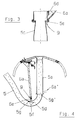
- FIG. 3 In the variant of Figure 3 is - in the direction of flow shortly after the retraction 5c - a supply air nozzle 5e is provided, which the flow in the feed line 5 with connects the environment.
- the negative pressure behind the confiscation 5c is sufficient, in addition to the return line 6 also apply suction pressure to the surroundings, so that enough air is available through the supply air 9 stands around a blockage of a conveyor cross-section downstream to avoid.
- Figure 3 is also a slide 6d indicated, with which the return line 6a can be blocked off in whole or in part.
- This return line 6a can also, as shown in FIGS. 4, 4a, into an upstream of the vertical part 5a, here part 5d formed as a manifold the lead 5 open out, approximately in its horizontal Section 5f; it depends on the flow conditions opposed to the confluence instead of a confiscation a flat nozzle plate 5g precedes the flow cross section also draws in like a nozzle, however asymmetrical to the large radius of curvature of the section 5f shifting where the flow rate is highest.
- a supply air nozzle 6e is at this version provided within the return line 6a.
- the embodiment is the rigid vertical part 5a, through which the material to be distributed 2 is transported vertically upwards is, as in the embodiments according to 1 to 4, with a nozzle-like retraction 5c educated.
- the return line ends above the confiscation 5c 6a.
- a conically shaped piece of pipe 6d has been used in the vertical part 5a.
- This conical pipe section has a 5c directed towards the retraction smaller diameter, this being chosen is that the material to be distributed 2 is approximately annular in the lead 5 is introduced. This way you can reach a more favorable distribution of the returned goods 2nd
Description
- Fig.1
- eine Gesamtansicht einer erfindungsgemäßen Verteilmaschine,
- Fig.2
- eine Einzelheit A aus Fig.1,
- Fig.3
- eine Einzelheit B aus Fig.2 in einer gegenüber Fig.1 und 2 etwas veränderten Ausführung,
- Fig.4 und Fig.4a
- je einen Verteilerkopf gemäß Fig.1 mit leicht veränderter Anordnung der Rückleitung und
- Fig. 5
- ein weiteres Ausführungsbeispiel gemäß der Erfindung,
Claims (19)
- Landwirtschaftliche pneumatische Verteilmaschine zum Verteilen eines vorzugsweise körnigen Verteilgutes, insbesondere eines Saatgutes oder eines Düngers aus einem Vorratsbehälter mit einer Dosiereinrichtung für die dosierte Förderung des Verteilgutes aus dem Vorratsbehälter über eine Zuleitung zu einem Verteilerkopf, und mit mehreren an dem Verteilerkopf angeschlossenen Verteilerleitungen zur Zuführung von jeweils einer Teilmenge des Verteilgutes zu jeweils einem Streuer für das Verteilgut, insbesondere einem Säschar oder einem Düngerstreuer, wobei zumindest ein Teil der Verteilerleitungen an ihren Abgängen aus dem Verteilerkopf mit Absperreinrichtungen versehen ist, die so schaltbar sind, daß die Förderung des Verteilgutes zu dem jeweils zugehörigen Streuer abgesperrt ist und stattdessen über eine jeweils zugehörige Rückleitung erfolgt, dadurch gekennzeichnet, daß
die Rückleitung (6a,6a') bypass-artig in der Zuleitung (5) zu dem Verteilerkopf (6) mündet und daß bei gesperrten Verteilerleitungen (71) die Dosiereinrichtung (3) so eingeregelt oder -gesteuert wird, daß die ausgebrachte, auf die Bestellfläche bezogene Menge des Verteilgutes (2) sich gegenüber derjenigen bei entsprechend aktivierten Verteilerleitungen nicht verändert. - Verteilmaschine nach Anspruch 1, dadurch gekennzeichnet, daß die Sperrung bestimmter Verteilerleitungen für eine Fahrgassenschaltung vorgesehen ist, die selbsttätig oder manuell aktivierbar ist und die dabei mittels der Absperreinrichtungen (8) diejenigen Verteilerleitungen (71) absperrt, deren Streuer in dem Weg der Schlepperräder eines die Verteilmaschine bewegenden Schleppers enden.
- Verteilmaschine nach Anspruch 1 oder 2, dadurch gekennzeichnet, daß die Rückleitung (6a,6a') in einem vorzugsweise senkrechten, unmittelbar vor dem Verteilerkopf (6) befindlichen Teil (5a) der Zuleitung (5) mündet.
- Verteilmaschine nach Anspruch 1 oder 2, dadurch gekennzeichnet, daß die Rückleitung (6a,6a') in einem vorzugsweise gekrümmten, vor dem Verteilerkopf (6) befindlichen Teil (5d) der Zuleitung (5), beispielsweise in einem waagerechten Bereich (5f) dieses Teiles (5d) und insbesondere an der Stelle mit der größten Krümmung, mündet.
- Verteilmaschine nach einem der Ansprüche 1 bis 4, dadurch gekennzeichnet, daß die Zuleitung (5) in Förderrichtung vor, vorzugsweise unmittelbar vor dem Anschluß der Rückleitung (6a,6a') in die Zuleitung (5) eine düsenartige erste Einziehung (5c) ihres Querschnitts aufweist, die so bemessen ist, daß das Verteilgut (2) aus der Rückleitung (6a,6a') in die Zuleitung (5) angesaugt wird.
- Verteilmaschine nach einem der Ansprüche 1 bis 5, dadurch gekennzeichnet, daß die Zuleitung (5) vor, vorzugsweise unmittelbar vor ihrer Einmündung in den Verteilerkopf (6) eine düsenartige zweite Einziehung ( 5b) aufweist.
- Verteilmaschine nach einem der Ansprüche 1 bis 6, dadurch gekennzeichnet, daß die Absperreinrichtungen (8) in Stutzen (7a) vorgesehen sind, die von dem Verteilerkopf (6) trennbar und mit denen die Verteilerleitungen (7) verbindbar sind.
- Verteilmaschine nach einem der Ansprüche 1 bis 7, dadurch gekennzeichnet, daß in den Stutzen (7a) der absperrbaren Verteilerleitungen (71) jeweils die von der zugehörigen Absperreinrichtung (8) beeinflußte Abzweigung (7d) für die Rückleitung (6a,6a') vorgesehen ist.
- Verteilmaschine nach einem der Ansprüche 1 bis 8, dadurch gekennzeichnet, daß die Absperreinrichtungen (8) als elektromagnetisch betätigbare Klappen ausgebildet sind.
- Verteilmaschine nach einem der Ansprüche 8 oder 9, dadurch gekennzeichnet, daß die Abzweigungen (7d) jeweils in einem an dem Stutzen (7a) - gegebenenfalls abgedichtet - anschließenden Trichter (6b) münden, an dem die zugehörige Rückleitung (6a,6a') angeschlossen ist.
- Verteilmaschine nach Anspruch 9, dadurch gekennzeichnet, daß mindestens zwei Abzweigungen (7d) in einem Trichter (6b) enden.
- Verteilmaschine nach einem der Ansprüche 5 bis 11, dadurch gekennzeichnet, daß die Einziehung (5c) rotationssymmetrisch zu der Achse der Zuleitung (5) ausgebildet ist.
- Verteilmaschine nach Anspruch 12, dadurch gekennzeichnet, daß die Einziehung (5c) eine kegelige Mantelfläche aufweist.
- Verteilmaschine nach einem der Ansprüche 5 bis 11, dadurch gekennzeichnet, daß die Einziehung (5c) von einem in der Zuleitung (5) vorgesehenen, vorzugsweise ebenen, den Strömungsquerschnitt in der Zuleitung (5) in Strömungsrichtung sukzessive bis zur Einmündung der Rückleitung (6a,6a') vermindernden Düsenblech (5g,5g') gebildet wird.
- Verteilmaschine nach Anspruch 14, dadurch gekennzeichnet, daß das Düsenblech (5g,5g') so angeordnet ist, daß ein kreisförmiger Strömungsquerschnitt in Strömungsrichtung sukzessive bis zur Einmündung der Rückleitung (6a,6a') durch einen in Strömungsrichtung sukzessive sich vergrößernden Kreisabschnitt vermindert wird.
- Verteilmaschine nach einem der Ansprüche 1 bis 15, dadurch gekennzeichnet, daß in Strömungsrichtung unmittelbar hinter der Einziehung (5c), beispielsweise in der Zuleitung (5) oder der Rückleitung (6a,6a'), eine Zuluftdüse (5e,6e) für eine der Umgebung entnommene Zuluft (9) vorgesehen ist.
- Verteilmaschine nach einem der Ansprüche 1 bis 16, dadurch gekennzeichnet, daß die Rückleitung (6a,6a') absperrbar ausgebildet ist.
- Verteilmaschine nach Anspruch 17, dadurch gekennzeichnet, daß in der Rückleitung (6a,6a'), vorzugsweise zugsweise kurz vor ihrer Einmündung in die Zuleitung (5), ein Schieber (6d) vorgesehen ist.
- Verteilmaschine nach einem der Ansprüche 1 bis 18, dadurch gekennzeichnet, daß strömungsmäßig gesehen oberhalb der Einziehung (5c) ein konischer Rohrabschnitt eingesetzt ist, der sich entgegen der Strömungsrichtung hin verjüngt und der die Rückleitung (6a) ganz oder teilweise übergreift.
Applications Claiming Priority (3)
| Application Number | Priority Date | Filing Date | Title |
|---|---|---|---|
| DE9313779U DE9313779U1 (de) | 1993-09-11 | 1993-09-11 | Landwirtschaftliche pneumatische Verteilmaschine |
| DE9313779U | 1993-09-11 | ||
| EP94111112A EP0642729B1 (de) | 1993-09-11 | 1994-07-16 | Landwirtschaftliche pneumatische Verteilmaschine |
Related Parent Applications (2)
| Application Number | Title | Priority Date | Filing Date |
|---|---|---|---|
| EP94111112A Division EP0642729B1 (de) | 1993-09-11 | 1994-07-16 | Landwirtschaftliche pneumatische Verteilmaschine |
| EP94111112.2 Division | 1994-07-16 |
Publications (3)
| Publication Number | Publication Date |
|---|---|
| EP0752203A2 EP0752203A2 (de) | 1997-01-08 |
| EP0752203A3 EP0752203A3 (de) | 1997-04-02 |
| EP0752203B1 true EP0752203B1 (de) | 2000-09-13 |
Family
ID=6898009
Family Applications (2)
| Application Number | Title | Priority Date | Filing Date |
|---|---|---|---|
| EP96114671A Expired - Lifetime EP0752203B1 (de) | 1993-09-11 | 1994-07-16 | Landwirtschaftliche pneumatische Verteilmaschine |
| EP94111112A Expired - Lifetime EP0642729B1 (de) | 1993-09-11 | 1994-07-16 | Landwirtschaftliche pneumatische Verteilmaschine |
Family Applications After (1)
| Application Number | Title | Priority Date | Filing Date |
|---|---|---|---|
| EP94111112A Expired - Lifetime EP0642729B1 (de) | 1993-09-11 | 1994-07-16 | Landwirtschaftliche pneumatische Verteilmaschine |
Country Status (2)
| Country | Link |
|---|---|
| EP (2) | EP0752203B1 (de) |
| DE (3) | DE9313779U1 (de) |
Cited By (6)
| Publication number | Priority date | Publication date | Assignee | Title |
|---|---|---|---|---|
| DE19745098C2 (de) * | 1997-10-11 | 2003-01-30 | Lemken Gmbh & Co Kg | Pneumatische Dillmaschine mit Saatgutrückführung |
| WO2004050509A1 (en) * | 2002-12-04 | 2004-06-17 | T.A.C.A. International Pty Ltd | Method and apparatus for dispensing of particulate material |
| DE102009031066A1 (de) | 2009-06-30 | 2011-01-13 | Lemken Gmbh & Co. Kg | Verteiler für pneumatische Drillmaschine |
| EP2695508A1 (de) | 2012-08-09 | 2014-02-12 | Alois Pöttinger Maschinenfabrik GmbH | Verteilerkopf für eine Sä- und/oder Düngemaschine |
| DE102013000758A1 (de) | 2013-01-16 | 2014-07-17 | Alois Pöttinger Maschinenfabrik Ges.m.b.H. | Verteilerkopf für eine Sä- und/oder Düngemaschine |
| EP4000364A1 (de) | 2020-11-24 | 2022-05-25 | Pöttinger Landtechnik GmbH | Verteilerkopf für eine sä- und/oder düngemaschine |
Families Citing this family (17)
| Publication number | Priority date | Publication date | Assignee | Title |
|---|---|---|---|---|
| DE4411240C2 (de) * | 1994-03-31 | 2001-12-20 | Kverneland Accord Landmaschine | Verteilerkopf für eine Verteilmaschine für Saatgut und/oder Dünger |
| DE19538626A1 (de) * | 1995-09-15 | 1997-03-20 | Amazonen Werke Dreyer H | Landwirtschaftliche Verteilmaschine |
| SE9504487L (sv) * | 1995-12-14 | 1997-06-15 | Crister Stark | Jordbruksmaskin |
| DE19613785C2 (de) * | 1996-04-04 | 2002-08-22 | Kverneland Accord Gmbh & Co Kg | Abluftleitung für eine pneumatisch arbeitende Verteilmaschine |
| DE19711942A1 (de) * | 1997-03-21 | 1998-09-24 | Amazonen Werke Dreyer H | Landwirtschaftliche Verteilmaschine |
| DE102009003791A1 (de) * | 2009-04-16 | 2010-10-21 | Amazonen-Werke H. Dreyer Gmbh & Co. Kg | Pneumatisch arbeitende Verteilmaschine |
| US8196534B2 (en) † | 2009-12-03 | 2012-06-12 | Deere & Company | Volumetric metering system with clutch based sectional shut-off |
| WO2012170690A2 (en) * | 2011-06-10 | 2012-12-13 | Great Plains Manufacturing, Incorporated | Seed distribution tower for an air seeder |
| EA029183B1 (ru) * | 2014-06-11 | 2018-02-28 | Республиканское Унитарное Предприятие "Научно-Практический Центр Национальной Академии Наук Беларуси По Механизации Сельского Хозяйства" | Сеялка с пневматическим высевающим аппаратом |
| ITUB20152403A1 (it) | 2015-07-22 | 2017-01-22 | Matermacc S P A | Dispositivo di distribuzione di fertilizzanti. |
| DE102015116378A1 (de) | 2015-09-28 | 2017-03-30 | Horsch Maschinen Gmbh | Verteilturm einer landwirtschaftlichen Verteilmaschine |
| DE102017203854A1 (de) | 2017-03-08 | 2018-09-13 | Horsch Maschinen Gmbh | Verteilerturm einer landwirtschaftlichen Maschine, landwirtschaftliche Maschine und Verfahren zum Betreiben einer solchen landwirtschaftlichen Maschine |
| DE102017113488A1 (de) * | 2017-06-20 | 2018-12-20 | Amazonen-Werke H. Dreyer Gmbh & Co. Kg | Landwirtschaftliche pneumatische Verteilmaschine |
| DE102017113487A1 (de) | 2017-06-20 | 2018-12-20 | Amazonen-Werke H. Dreyer Gmbh & Co. Kg | Landwirtschaftliche pneumatische Verteilmaschine |
| DE102018102582A1 (de) * | 2018-02-06 | 2019-08-08 | Amazonen-Werke H. Dreyer Gmbh & Co. Kg | Verfahren zum Ausbringen von körnigem Material |
| DE102019128863B4 (de) * | 2019-10-25 | 2023-06-29 | Amazonen-Werke H. Dreyer SE & Co. KG | Verteilerkopf für eine pneumatisch arbeitende Verteilmaschine |
| DE102020109791A1 (de) | 2020-04-08 | 2021-10-14 | Amazonen-Werke H. Dreyer SE & Co. KG | Pneumatische Verteilmaschine |
Family Cites Families (3)
| Publication number | Priority date | Publication date | Assignee | Title |
|---|---|---|---|---|
| DE3843141A1 (de) * | 1988-12-22 | 1990-06-28 | Amazonen Werke Dreyer H | Verteilmaschine |
| US5028009A (en) * | 1989-12-22 | 1991-07-02 | Ag-Chem Equipment Co., Inc. | Distributor head for use with booms having shut-off capability |
| US5074228A (en) * | 1990-10-04 | 1991-12-24 | Daws Gregory R | Apparatus and methods for selectively creating tramlines |
-
1993
- 1993-09-11 DE DE9313779U patent/DE9313779U1/de not_active Expired - Lifetime
-
1994
- 1994-07-16 DE DE59402728T patent/DE59402728D1/de not_active Expired - Lifetime
- 1994-07-16 DE DE59409523T patent/DE59409523D1/de not_active Expired - Lifetime
- 1994-07-16 EP EP96114671A patent/EP0752203B1/de not_active Expired - Lifetime
- 1994-07-16 EP EP94111112A patent/EP0642729B1/de not_active Expired - Lifetime
Cited By (10)
| Publication number | Priority date | Publication date | Assignee | Title |
|---|---|---|---|---|
| DE19745098C2 (de) * | 1997-10-11 | 2003-01-30 | Lemken Gmbh & Co Kg | Pneumatische Dillmaschine mit Saatgutrückführung |
| WO2004050509A1 (en) * | 2002-12-04 | 2004-06-17 | T.A.C.A. International Pty Ltd | Method and apparatus for dispensing of particulate material |
| DE102009031066A1 (de) | 2009-06-30 | 2011-01-13 | Lemken Gmbh & Co. Kg | Verteiler für pneumatische Drillmaschine |
| DE102009031066B4 (de) * | 2009-06-30 | 2015-10-01 | Lemken Gmbh & Co. Kg | Verteiler für pneumatische Drillmaschine |
| EP2695508A1 (de) | 2012-08-09 | 2014-02-12 | Alois Pöttinger Maschinenfabrik GmbH | Verteilerkopf für eine Sä- und/oder Düngemaschine |
| DE102012015731A1 (de) | 2012-08-09 | 2014-02-13 | Alois Pöttinger Maschinenfabrik Ges.m.b.H. | Verteilerkopf für eine Sä- und/oder Düngemaschine |
| DE102013000758A1 (de) | 2013-01-16 | 2014-07-17 | Alois Pöttinger Maschinenfabrik Ges.m.b.H. | Verteilerkopf für eine Sä- und/oder Düngemaschine |
| EP2756744A1 (de) | 2013-01-16 | 2014-07-23 | Alois Pöttinger Maschinenfabrik GmbH | Verteilerkopf für eine Sä- und/oder Düngemaschine |
| EP4000364A1 (de) | 2020-11-24 | 2022-05-25 | Pöttinger Landtechnik GmbH | Verteilerkopf für eine sä- und/oder düngemaschine |
| DE102020130985A1 (de) | 2020-11-24 | 2022-05-25 | Pöttinger Landtechnik Gmbh | Verteilerkopf für eine Sä- und/oder Düngemaschine |
Also Published As
| Publication number | Publication date |
|---|---|
| DE59409523D1 (de) | 2000-10-19 |
| EP0752203A2 (de) | 1997-01-08 |
| EP0642729B1 (de) | 1997-05-14 |
| EP0642729A1 (de) | 1995-03-15 |
| EP0752203A3 (de) | 1997-04-02 |
| DE9313779U1 (de) | 1993-11-18 |
| DE59402728D1 (de) | 1997-06-19 |
Similar Documents
| Publication | Publication Date | Title |
|---|---|---|
| EP0752203B1 (de) | Landwirtschaftliche pneumatische Verteilmaschine | |
| EP3372064B1 (de) | Verteilerturm einer landwirtschaftlichen maschine, landwirtschaftliche maschine und verfahren zum betreiben einer solchen landwirtschaftlichen maschine | |
| EP3284332B1 (de) | Verteilmaschine und verfahren zur aussaat von granulatartigem verteilgut | |
| EP0898861B1 (de) | Sägerät | |
| EP0897660B2 (de) | Ausbringguttrenner zum Unterbrechen des Stroms von Ausbringgut zwischen einem Tank und einem Messsystem | |
| EP1003360B1 (de) | Messsystem eines sägeräts | |
| EP0799560B1 (de) | Abluftleitung für eine pneumatisch arbeitende Verteilmaschine | |
| EP1003359B1 (de) | Verteilersystem eines sägeräts | |
| EP2695508B1 (de) | Verteilerkopf für eine Sä- und/oder Düngemaschine | |
| EP3836772A1 (de) | Saeaggregat fuer eine einzelkornsaemaschine | |
| EP3417689A1 (de) | Landwirtschaftliche pneumatische verteilmaschine | |
| DE102011054862A1 (de) | Bodenbearbeitungsgerät und Verfahren zur Einbringung von wasserspeicherndem Material und/oder Düngemittel und/oder Saatgut in den Erdboden | |
| EP3417688A1 (de) | Landwirtschaftliche pneumatische verteilmaschine | |
| DE2807639C2 (de) | Vorrichtung und Verfahren zum Einspritzen von körnigen Materialien in den Erdboden | |
| DD297298A5 (de) | Vorrichtung zum einbringen von samen in den boden | |
| WO2021083536A1 (de) | Pneumatische verteilmaschine | |
| DE102006021473A1 (de) | Sämaschine | |
| WO2019030309A1 (de) | Säschar sowie sämaschine | |
| DE102018130717A1 (de) | Landwirtschaftliche Verteilmaschine und Verfahren zum Ausbringen von granularem Verteilgut | |
| DE102009012849A1 (de) | Pneumatische Direktsämaschine | |
| DE3911156A1 (de) | Landwirtschaftliche verteilmaschine | |
| EP4305943A1 (de) | Anordnung zur pneumatischen förderung eines hilfsstoffs zu reiheneinheiten einer sämaschine | |
| DE10010347A1 (de) | Vorrichtung zum Ausbringen von Gut auf landwirtschaftliche Flächen | |
| DE102022108775A1 (de) | Landwirtschaftliche Verteilmaschine | |
| DE4410549A1 (de) | Pneumatische Verteilmaschine |
Legal Events
| Date | Code | Title | Description |
|---|---|---|---|
| PUAI | Public reference made under article 153(3) epc to a published international application that has entered the european phase |
Free format text: ORIGINAL CODE: 0009012 |
|
| AC | Divisional application: reference to earlier application |
Ref document number: 642729 Country of ref document: EP |
|
| AK | Designated contracting states |
Kind code of ref document: A2 Designated state(s): DE FR |
|
| PUAL | Search report despatched |
Free format text: ORIGINAL CODE: 0009013 |
|
| AK | Designated contracting states |
Kind code of ref document: A3 Designated state(s): DE FR |
|
| 17P | Request for examination filed |
Effective date: 19970721 |
|
| GRAG | Despatch of communication of intention to grant |
Free format text: ORIGINAL CODE: EPIDOS AGRA |
|
| 17Q | First examination report despatched |
Effective date: 19991227 |
|
| GRAG | Despatch of communication of intention to grant |
Free format text: ORIGINAL CODE: EPIDOS AGRA |
|
| GRAH | Despatch of communication of intention to grant a patent |
Free format text: ORIGINAL CODE: EPIDOS IGRA |
|
| GRAH | Despatch of communication of intention to grant a patent |
Free format text: ORIGINAL CODE: EPIDOS IGRA |
|
| GRAA | (expected) grant |
Free format text: ORIGINAL CODE: 0009210 |
|
| AC | Divisional application: reference to earlier application |
Ref document number: 642729 Country of ref document: EP |
|
| AK | Designated contracting states |
Kind code of ref document: B1 Designated state(s): DE FR |
|
| REF | Corresponds to: |
Ref document number: 59409523 Country of ref document: DE Date of ref document: 20001019 |
|
| ET | Fr: translation filed | ||
| PLBQ | Unpublished change to opponent data |
Free format text: ORIGINAL CODE: EPIDOS OPPO |
|
| PLBI | Opposition filed |
Free format text: ORIGINAL CODE: 0009260 |
|
| PLBF | Reply of patent proprietor to notice(s) of opposition |
Free format text: ORIGINAL CODE: EPIDOS OBSO |
|
| 26 | Opposition filed |
Opponent name: AMAZONEN-WERKE H. DREYER GMBH & CO. KG Effective date: 20010613 |
|
| PLBF | Reply of patent proprietor to notice(s) of opposition |
Free format text: ORIGINAL CODE: EPIDOS OBSO |
|
| RAP2 | Party data changed (patent owner data changed or rights of a patent transferred) |
Owner name: RABE AGRARSYSTEME GMBH & CO. KG |
|
| PLBQ | Unpublished change to opponent data |
Free format text: ORIGINAL CODE: EPIDOS OPPO |
|
| PLAB | Opposition data, opponent's data or that of the opponent's representative modified |
Free format text: ORIGINAL CODE: 0009299OPPO |
|
| R26 | Opposition filed (corrected) |
Opponent name: AMAZONEN-WERKEH. DREYER GMBH & CO. KG Effective date: 20010613 |
|
| PLCK | Communication despatched that opposition was rejected |
Free format text: ORIGINAL CODE: EPIDOSNREJ1 |
|
| PLBN | Opposition rejected |
Free format text: ORIGINAL CODE: 0009273 |
|
| STAA | Information on the status of an ep patent application or granted ep patent |
Free format text: STATUS: OPPOSITION REJECTED |
|
| 27O | Opposition rejected |
Effective date: 20030519 |
|
| REG | Reference to a national code |
Ref country code: FR Ref legal event code: TP |
|
| PGFP | Annual fee paid to national office [announced via postgrant information from national office to epo] |
Ref country code: DE Payment date: 20130918 Year of fee payment: 20 |
|
| PGFP | Annual fee paid to national office [announced via postgrant information from national office to epo] |
Ref country code: FR Payment date: 20130719 Year of fee payment: 20 |
|
| REG | Reference to a national code |
Ref country code: DE Ref legal event code: R071 Ref document number: 59409523 Country of ref document: DE |
|
| PG25 | Lapsed in a contracting state [announced via postgrant information from national office to epo] |
Ref country code: DE Free format text: LAPSE BECAUSE OF EXPIRATION OF PROTECTION Effective date: 20140717 |