EP0751630A2 - Emetteur de station de base à accès multiple par division de code - Google Patents
Emetteur de station de base à accès multiple par division de code Download PDFInfo
- Publication number
- EP0751630A2 EP0751630A2 EP19960110408 EP96110408A EP0751630A2 EP 0751630 A2 EP0751630 A2 EP 0751630A2 EP 19960110408 EP19960110408 EP 19960110408 EP 96110408 A EP96110408 A EP 96110408A EP 0751630 A2 EP0751630 A2 EP 0751630A2
- Authority
- EP
- European Patent Office
- Prior art keywords
- signal
- spread
- amplitude
- multiplexed
- transmission
- Prior art date
- Legal status (The legal status is an assumption and is not a legal conclusion. Google has not performed a legal analysis and makes no representation as to the accuracy of the status listed.)
- Granted
Links
Images


Classifications
-
- H—ELECTRICITY
- H04—ELECTRIC COMMUNICATION TECHNIQUE
- H04J—MULTIPLEX COMMUNICATION
- H04J13/00—Code division multiplex systems
- H04J13/10—Code generation
- H04J13/12—Generation of orthogonal codes
-
- H—ELECTRICITY
- H04—ELECTRIC COMMUNICATION TECHNIQUE
- H04B—TRANSMISSION
- H04B1/00—Details of transmission systems, not covered by a single one of groups H04B3/00 - H04B13/00; Details of transmission systems not characterised by the medium used for transmission
- H04B1/69—Spread spectrum techniques
- H04B1/707—Spread spectrum techniques using direct sequence modulation
-
- H—ELECTRICITY
- H04—ELECTRIC COMMUNICATION TECHNIQUE
- H04W—WIRELESS COMMUNICATION NETWORKS
- H04W88/00—Devices specially adapted for wireless communication networks, e.g. terminals, base stations or access point devices
- H04W88/08—Access point devices
-
- H—ELECTRICITY
- H04—ELECTRIC COMMUNICATION TECHNIQUE
- H04B—TRANSMISSION
- H04B2201/00—Indexing scheme relating to details of transmission systems not covered by a single group of H04B3/00 - H04B13/00
- H04B2201/69—Orthogonal indexing scheme relating to spread spectrum techniques in general
- H04B2201/707—Orthogonal indexing scheme relating to spread spectrum techniques in general relating to direct sequence modulation
- H04B2201/70706—Orthogonal indexing scheme relating to spread spectrum techniques in general relating to direct sequence modulation with means for reducing the peak-to-average power ratio
Definitions
- the present invention generally relates to a code division multiple access (CDMA) base station transmitter, and particularly, to a CDMA base station transmitter installed in a base station of a mobile communication system of a CDMA type, such as a vehicle telephone system or a portable telephone system or cellular system, permitting an ensured suppression of transmission peak power.
- CDMA code division multiple access
- carriers are each modulated by a ⁇ /4 shift QPSK (quadriphase shift keying) system or a GMSK (Gaussian filtered minimum phase shift keying) system so that the amplitude is constant or small of variation. It therefore is possible to independently amplify each carrier by a class "AB” or "C", power amplifier with a desirable efficiency.
- QPSK quadrature shift keying
- GMSK Gausian filtered minimum phase shift keying
- the carriers are multiplexed after the power amplification, using a combiner to minimize a power loss, which is subjected to restrictions such that the carriers cannot be multiplexed if they are not sufficiently distant from each other, and that a frequency change cannot be readily carried out.
- Fig. 1 shows a conventional CDMA base station transmitter, which comprises a digital base band processing section 1001, an analog base band/RF section 1002 and a transmission antenna 1012.
- the digital base band processing section 1001 includes a total of K spectrum spread units 1003, 1004, ⁇ , 1005, where K is a positive integer, a summer 1006 and a roll-off filter 1008.
- a total of K transmission data for a total of K channels. i.e. channel-1 transmission data d1 to channel-k transmission data dK, are input to the K spread units 1003, 1004, ⁇ , 1005, where they are spectrally spread by a total of K different codes one-to-one assigned to the K channels so that the channel-1 transmission data d1 to channel-k transmission data dK are converted into channel-1 spread data t1 to channel-k spread data tK, respectively.
- the summer 1006 sums up the total of K spread data t1 to tK to provide a multiplexed spread signal s1.
- the roll-off filter 1008 of which a roll-off characteristic is preset to have an occupied band width equivalent to a predetermined value, performs a spectrum shaping of the multiplexed spread signal s1 to provide a digital base band signal s3, which is output to the analog base band/RF section 1002.
- the analog base band/RF section 1002 includes a digital-to-analog (D/A) converter 1009, a modulator 1010 and a transmission power amplifier 1011.
- the D/A converter 1009 serves as an analog base band circuit for converting the digital base band signal s3 into an analog base band signal s4 that is input to the modulator 1010, which responds thereto for modulating a carrier of a predetermined frequency to provide a radio frequency transmission signal r1, of which power is amplified at the transmission power amplifier 1011 to provide a transmission signal r2, which is output for transmission from the transmission antenna 1012.
- the CDMA system itself can cope with all channels by using a single carrier, without the need of a plurality of radio sections that are necessary for the TDMA or FDMA system, which means that the CDMA system works with a single analog base band/RF section at each base station (with a single transmission antenna when using sector antennae).
- the multiplexed base band signal is a multilevel signal as a matter of course, so that a wide dynamic range and a high linearity are needed at the roll-off filter of the digital base band processing section as well as at the modulator and the transmission power amplifier of the analog base band/RF section.
- Fig. 2 shows an arrangement of the conventional system as an amplitude control transmitter for multi carrier modulation.
- the amplitude control transmitter comprises a serial/parallel converter 1101 for a serial/parallel conversion of input transmission data, a four-channel IQ (I: in-phase component; Q: quadrature component) coder section 1102, a four-channel roll-off filter section 1103, a four-channel subcarrier modulator section 1104, a two-channel summer section 1105 corresponding to the IQ components, an amplitude limiter 1106 for limiting amplitudes of outputs of the summer section 1105, and a band limiting filter 1107 for limiting bands of outputs of the amplitude limiter 1106 to provide desirable digital base band signals.
- IQ in-phase component
- Q quadrature component
- the conventional envelope control modulation device for multi carrier digital modulation (as the amplitude control transmitter for multi carrier modulation) has peak power thereof reduced by provision of a combination of the amplitude limiter 1106 and the band limiting filter 1107 to a multi subcarrier modulation.
- each subcarrier has a limited amplitude causing other subcarriers' spectral distortions, which are kept within an own occupied band, permitting the reduction of peak power and a limitation of leakage power from the occupied band to be both effected.
- this conventional system is applicable merely when a plurality of subcarriers are used, and is ineffective if all channels are accommodated to a single carrier like the CDMA system. This is because transmission data, as their waveforms are once spectrum-shaped by the roll-off filters and amplitude-limited, again undergo band limitations so that they have their spectral distributions restored to original ones, as well as their temporal waveforms, thus resulting in lost effects on limitation of peak power.
- a base station transmitter of a mobile communication system It becomes more difficult for a base station transmitter of a mobile communication system to permit an increased scale of integration such as of an LSI, as the transmitter has increased numbers of analog circuits and radio frequency circuits, or to be adaptive for an advanced miniaturization or an improved cost effect, as the transmitter is subjected to a whole inpection for adjustment.
- the CDMA system is a solution to overcome such problems, but employs a multiplexed spread signal large of amplitude variation, needing a very wide dynamic range and a high linearity to be both secured at an analog base band section, a modulator and a transmission power amplifier.
- the average power is a 100-fold of that of a single channel, with the possibility of having a 100-folded amplitude when the channels are summed up in phase, thus having as large peak power as a 100-fold (20 dB) of average power, needing a linearity to be kept over a range up to a level higher by 20 dB than the average power at respective circuit sections including the analog base band section, the modulator and the transmission power amplifier, which is problematic in particular at the transmission power amplifier, as it is for a base station for large power transmission. It should thus be necessary in this case for a transmission of 1 W/channel in average to provide a transmission power amplifier of a 10 kW output, which is impractical.
- CDMA code division multiple access
- a code division multiple access base station transmitter which is placed in a mobile communication system base station transmitting and receiving a plurality of communication channels by a direct spread code division multiple access system (DS-CDMA) and ensures suppression of transmission peak power while transmitting.
- DS-CDMA direct spread code division multiple access system
- a summing synthesizer for summing up the spread signals output from the spread units to output a multiplexed spread signal; a limiter for performing an amplitude limitation of the multiplexed spread signal output from the summing synthesizer; a roll-off filter for carrying out a spectrum shaping of the amplitude-limited multiplexed spread signal so that an occupied band width of the amplitude-limited multiplexed spread signal is included within a predetermined value; a digital-to-analog converter for converting a digital base band signal of the spectrum-shaped multiplexed spread signal into an analog base band signal; a modulator for converting the analog base band signal into a radio frequency signal; a transmission power amplifier for amplifying the radio frequency signal output from the modulator; and a transmission antenna for transmitting the amplified radio frequency signal output from the transmission power amplifier.
- the limiter includes a polar coordinate conversion circuit for converting I and Q components of the multiplexed spread signal to an amplitude component and a phase component of the multiplexed spread signal; a maximum value limitation circuit for limiting a maximum value of the amplitude component of the multiplexed spread signal to a level predetermined based on a characteristic of the transmission power amplifier and the allowable mutual interference between a plurality of communication channels; and an orthogonal coordinate conversion circuit for converting the maximum value limited amplitude component and the phase component of the multiplexed spread signal into I and Q components.
- the limiter is composed of a read only memory (ROM) which is addressed by the multiplexed spread signal to read data out of the read only memory to obtain an amplitude limited multiplexed spread signal.
- ROM read only memory
- the limiter is preferably composed of two absolute value limitation circuits for limiting an I component as an in-phase component and a Q component as a quadrature component of the multiplexed spread signal to values predetermined based on a characteristic of the transmission power amplifier and the allowable mutual interference between a plurality of communication channels.
- a CDMA base station transmitter of the present invention after an amplitude limitation is applied to a multiplexed spread signal obtained by summing up a plurality of channel spread spectrum signals, the amplitude limited multiplexed spread signal is input to a roll-off filter to output a digital base band signal.
- the amplitude limitation is applied to the multiplexed spread signal in consideration of the conditions which prevent a destruction of orthogonality between the channels by the amplitude limitation to cause an occurrence of an interference between the channels and prevent a damage of stability of use of a plurality of communication channels and on the basis of the characteristic of a transmission power amplifier, thereby predetermining the maximum limitation value.
- the multiplexed spread signal is passed through the roll-off filter to output a digital base band signal and the digital base band signal is input to an analog base band/RF section wherein a dynamic range and linearity required for an analog base band section, a modulator and a transmission power amplifier can be remarkably decreased.
- the amplitude limitation can be implemented by a simple circuit including LSIs available on the market.
- Fig. 3 there is shown a code division multiple access (CDMA) base station transmitter according to one embodiment of the present invention.
- CDMA code division multiple access
- This transmitter has a basic construction and comprises a digital base band processing section 101 which applies a spread spectrum to a plurality of channels of transmission data to synthesize a digital base band signal and applies a spectrum shaping to the digital base band signal to output a processed digital base band signal s3, an analog base band/RF section 102 which converts the digital base band signal s3 fed from the digital base band processing section 101 into an analog base band signal s4 and produces an output transmission signal r2 based on a carrier modulation by the analog base band signal s4, and a transmission antenna 112 for transmitting the output transmission signal r2.
- the digital base band processing section 101 includes a plurality of spread units 103, 104, ⁇ , 105 of K channels for spreading a plurality of transmission data d1, d2 to dK by different spread codes to output spread signals t1, t2 to tK, a summer 106 for summing up the spread signals t1, t2 to tK fed from the spread units 103, 104 to 105 to output a multiplexed spread signal s1, a limiter 107 for limiting an amplitude of the multiplexed spread signal s1 to output an amplitude limit multiplexed spread signal s2, and a roll-off filter 108 for applying a spectrum shaping to the amplitude limit multiplexed spread signal s2 to output a digital base band signal s3.
- the analog base band/RF section 102 includes a digital-analog converter 109 for converting the digital base band signal s3 applied from the digital base band processing section 101 into an analog base band signal s4, a modulator 110 as an RF unit for modulating the carrier based on the analog base band signal s4 to output an RF (radio frequency) transmission signal r1, and a transmission power amplifier 111 for amplifying the RF transmission signal r1 to output an output transmission signal r2.
- the present invention is characterized by the limiter 107 added in the digital base band processing section 101.
- the CDMA base station transmitter has the K communication channels.
- a plurality of channel-1 transmission data d1, channel-2 transmission data d2 to channel-k transmission data dK of K channels are input to the respective K spread units 103, 104 to 105 wherein the channel-1 transmission data d1, the channel-2 transmission data d2 to the channel-k transmission data dK are spread by the different spread codes in order to separate the channels from each other to output a channel-1 spread signal t1, a channel-2 spread signal t2 to a channel-K spread signal tK, respectively.
- These channel-1, channel-2 to channel-K spread signals t1, t2 to tK are summed up in the summer 106.
- the multiplexed spread signal s1 output from the summer 106 is amplitude-limited so as to be equal to or lower than a predetermined value to output the amplitude limit multiplexed spread signal s2.
- the amplitude limit multiplexed spread signal s2 is passed through the roll-off filter 108 wherein the spectrum shaping is applied to the amplitude limit multiplexed spread signal s2 so that its occupied band width may be within a predetermined value.
- the digital base band signal s3 output from the roll-off filter 108 is a digital base band signal of the transmission signal, and thus in the same manner as a usual digital modulator, the digital base band signal s3 is converted into the analog base band signal s4 by the digital-analog converter 109 in the analog base band/RF section 102.
- the analog base band signal s4 is then converted into the RF transmission signal r1 based on the carrier modulation in the modulator 110 and the RF transmission signal r1 is amplified up to sufficient transmission power to cover its service area by the transmission power amplifier 111.
- the amplified output transmission signal r2 is then transmitted to the service area through the transmission antenna 112.
- BPSK binary phase modulation
- the channel-1 transmission data d1 to the channel-K transmission data dK have positive or negative values according to the contents of the transmission information.
- the transmission power of each channel is changed depending on a distance between the corresponding mobile station and the base station and a propagation condition and hence an absolute value of the channel-1, channel-2 or channel-K transmission data d1, d2 or dK is varied depending of the transmission power of each channel.
- the control of the transmission power itself is not directly related to the present invention and hence the description thereof can be omitted for brevity.
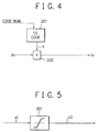
- Fig. 4 shows a first embodiment of each spread unit 103, 104 or 105 in the BPSK shown in Fig. 3, including a spread code generator 201 and a code multiplier 202.
- the spread code is specified every channel by a code number of a different code.
- mutually orthogonal codes such as Walsh codes or orthogonal Gold codes (obtained by adding "0" to the Gold codes) are assigned to the channels.
- a spread rate (a chip number per one symbol) is Ns
- a code length of the above-described orthogonal code is Ns.
- PN pseudo noise
- M system codes having a period of 2 41 -1 as spread codes are used besides the orthogonal codes having the aforementioned Ns period. That is, a spread code c is defined by a code obtained by an EX-OR of an orthogonal code with the period Ns and an M system code with a long period.
- the M system code is used for distinguishing among the base stations and the orthogonal code of the Ns period is among a plurality of channels in the same base station.
- the spread code c changes with the spread rate Ns times of the n channel transmission data dn and thus the spread signal tn also changes at the speed of Ns times.
- Fig. 5 illustrates a first embodiment of the limiter shown in Fig. 3 in the case of the BPSK.
- the spread signal includes only the same phase component (one component) and the limiter can be composed of only a simple absolute value limit circuit.
- the value Amax is mainly determined depending on the characteristic of the transmission power amplifier. When the value Amax is reduced, the peak power required for the transmission power amplifier can be lowered. However, the orthogonality between the channels is destroyed and hence an interference between the channels is caused.
- the transmission spectrum is distorted by a peak clip and leakage power to adjacent channels increases.
- the limiter functions before the roll-off filter and no distortion occurs in the transmission spectrum.
- a waveform distortion is caused by the limiter, transmission quality degradation can be suppressed to a low level because the amplitude limitation probability is low and the CDMA system based on the spread spectrum is strong against the distortion and the interference and because in the CDMA system, usually, a low rate error correction code (for example, a convolutional code with a rate of 1/3 and a constraint length of 9) is used in combination and the influence of the waveform distortion due to the amplitude limitation is dispersed and thinned.
- a low rate error correction code for example, a convolutional code with a rate of 1/3 and a constraint length of 9
- Fig. 6 shows a second embodiment of the spread unit shown in Fig. 3 in the case using the QPSK.
- the spread unit comprises a first spread code generator 401 for outputting a spread code in-phase component cI in response to a code number, a second spread code generator 402 for outputting a spread code quadrature component cQ in response to the code number, a first code multiplier 403 for multiplying channel n transmission data by the spread code in-phase component cI to output a channel n spread signal in-phase component tn(I), and a second code multiplier 404 for multiplying the channel n transmission data by the spread code quadrature component cQ to output a channel n spread signal quadrature component tn(Q).
- the information of the transmission data is binary, and as spread codes of the in-phase component (I component) and the quadrature component (Q component), different spread codes are used.
- the spread signal is expressed by two signals of the in-phase component and the quadrature component,
- Fig. 7 shows a third embodiment of the spread unit shown in Fig. 3 in the case using the QPSK.
- the spread unit comprises a third spread code generator 501 for outputting a spread code in-phase component cI in response to a code number, a fourth spread code generator 502 for outputting a spread code quadrature component cQ in response to the code number, a third code multiplier 503 for multiplying channel n transmission data in-phase component dn(I) by the spread code in-phase component cI to output a channel n spread signal II component, and a fourth code multiplier 504 for multiplying the channel n transmission data quadrature component by the spread code quadrature component cQ to output a channel n spread signal QI component, a fifth code multiplier 505 for multiplying the channel n transmission data in-phase component dn(I) by the spread code quadrature component cQ to output a channel n spread signal IQ component, a sixth code multiplier 506 for multiplying the channel n
- the information of the transmission data is a quadriphase of the channel n transmission in-phase component dn(I) and quadrature component dn(Q) and the spread code is also composed of the in-phase component and the quadrature component.
- Fig. 8 illustrates a second embodiment of the limiter shown in Fig. 3 in the case using the QPSK.
- the limiter comprises a polar coordinate conversion circuit 601, a maximum value limitation circuit 602 and an orthogonal coordinate conversion circuit 603.
- the polar coordinate conversion circuit 601 converts a multiplexed spread signal in-phase component s1(I) and a multiplexed spread signal quadrature component s1(Q) into an amplitude component and a phase component which are expressed by polar coordinates.
- the maximum value limitation circuit 602 limits so that the amplitude component may not exceed the predetermined value Amax.
- the orthogonal coordinate conversion circuit 603 converts the maximum value limited amplitude component and the phase component into orthogonal coordinates again to output an amplitude limit multiplexed spread signal in-phase component s2(I) and an amplitude limit multiplexed spread signal quadrature component s2(Q).
- An LSI for mutually converting between polar and orthogonal coordinates can be available.
- Fig. 9 illustrates a third embodiment of the limiter shown in Fig. 3.
- the limiter is composed of a ROM 701 which is addressed by the multiplexed spread signal in-phase component s1(I) and the multiplexed spread signal quadrature component s1(Q) to read out the amplitude limit multiplexed spread signal in-phase component s2(I) and the amplitude limit multiplexed spread signal quadrature component s2(Q).
- a ROM means that the limiter of the QPSK can be realized by a simple circuit when a chip rate is less than a medium speed (for example, less than 10 MHz).
- Fig. 10 shows a fourth embodiment of the limiter shown in Fig. 3.
- an absolute value limit circuit used in the first embodiment of the BPSK shown in Fig. 5 can apply to two absolute value limit circuits 801 and 802 for the in-phase and quadrature components of the input multiplexed spread signal.
- the limiter can be implemented by a very simple circuit.
- Fig. 11 shows one embodiment of the roll-off filter shown in Fig. 3.
- the roll-off filter comprises a pair of interpolation circuits 901 and 902 and a pair of digital low pass filters (LPFs) 903 and 904 for in-phase and quadrature components s2(I) and s2(Q) of an input amplitude limit multiplexed spread signal s2.
- the interpolation circuits 901 and 902 operate at a clock of M times (M is a positive integer of at least 2) of a chip rate and allow the input signal to pass one time per M clocks and zero to output the other M-1 times. That is, the interpolation circuits 901 and 902 output an oversampled pulse at a sampling rate of M times.
- the digital LPFs are low pass filters for performing a spectrum shaping of the transmission signal, for example, root raised cosine filters of a roll-off factor 30%.
- the digital LPF is usually implemented by an FIR (finite impulse response) filter for realizing a linear phase characteristic.
- FIR finite impulse response
- the interpolation circuits 901 and 902 and the digital LPFs are combined and a tap number is reduced to 1/M instead of which tap coefficients of M sets are switched per sample.
- An LSI having this construction is available at a market. By using this LSI on the market, the roll-off filter can be implemented.
- the signal is passed through the roll-off filter to check for an occurrence of a spectrum distortion to suppress a transmission peak voltage and to greatly improve the conditions such as a dynamic range and linearity of an analog base band section, a modulator and a transmission power amplifier of a CDMA base station transmitter having a simple construction.
- a CDMA base station transmitter of the present invention after a multiplexed spread signal is amplitude-limited, the signal is input to a roll-off filter to obtain a digital band base signal and only a simple circuit or a circuit using some available LSIs on the market is supplemented to reduce a peak power to an average power ratio of the transmission signal without causing any spectrum distortion and to remarkably improve the desired dynamic range and the linearity of an analog base band section, a modulator and a transmission power amplifier, particularly, to reduce a peak value so that an excessive linearity of the transmission power amplifier may not be required. Hence, remarkable efficiency increase of the transmission power amplifier and a low cost can be attained.
Priority Applications (1)
| Application Number | Priority Date | Filing Date | Title |
|---|---|---|---|
| EP20040017080 EP1471659B1 (fr) | 1995-06-30 | 1996-06-27 | Emetteur de station de base à accès multiple par division de code |
Applications Claiming Priority (3)
| Application Number | Priority Date | Filing Date | Title |
|---|---|---|---|
| JP18850195A JP2718398B2 (ja) | 1995-06-30 | 1995-06-30 | Cdma基地局送信装置 |
| JP18850195 | 1995-06-30 | ||
| JP188501/95 | 1995-06-30 |
Related Child Applications (1)
| Application Number | Title | Priority Date | Filing Date |
|---|---|---|---|
| EP20040017080 Division EP1471659B1 (fr) | 1995-06-30 | 1996-06-27 | Emetteur de station de base à accès multiple par division de code |
Publications (3)
| Publication Number | Publication Date |
|---|---|
| EP0751630A2 true EP0751630A2 (fr) | 1997-01-02 |
| EP0751630A3 EP0751630A3 (fr) | 1999-07-21 |
| EP0751630B1 EP0751630B1 (fr) | 2004-12-08 |
Family
ID=16224838
Family Applications (2)
| Application Number | Title | Priority Date | Filing Date |
|---|---|---|---|
| EP19960110408 Expired - Lifetime EP0751630B1 (fr) | 1995-06-30 | 1996-06-27 | Emetteur de station de base à accès multiple par division de code |
| EP20040017080 Expired - Lifetime EP1471659B1 (fr) | 1995-06-30 | 1996-06-27 | Emetteur de station de base à accès multiple par division de code |
Family Applications After (1)
| Application Number | Title | Priority Date | Filing Date |
|---|---|---|---|
| EP20040017080 Expired - Lifetime EP1471659B1 (fr) | 1995-06-30 | 1996-06-27 | Emetteur de station de base à accès multiple par division de code |
Country Status (6)
| Country | Link |
|---|---|
| US (1) | US5751705A (fr) |
| EP (2) | EP0751630B1 (fr) |
| JP (1) | JP2718398B2 (fr) |
| KR (1) | KR100200537B1 (fr) |
| CA (1) | CA2179977C (fr) |
| DE (2) | DE69633991T2 (fr) |
Cited By (24)
| Publication number | Priority date | Publication date | Assignee | Title |
|---|---|---|---|---|
| EP0874501A2 (fr) * | 1997-04-21 | 1998-10-28 | Nec Corporation | Ecrétage dans un modulateur en quadrature |
| EP0940925A1 (fr) * | 1998-03-05 | 1999-09-08 | Lucent Technologies Inc. | Système et procédé pour la réduction du rapport puissance de crête/puissance moyenne, dand des systèmes de AMDC |
| WO2000013343A1 (fr) | 1998-08-31 | 2000-03-09 | Qualcomm Incorporated | Procede d'eclatement du signal permettant de limiter la puissance de crete dans un systeme amcr |
| WO2000054429A1 (fr) * | 1999-03-10 | 2000-09-14 | Qualcomm Incorporated | Transmission de signal a amcr utilisant des rapports de signaux intrabande et hors bande |
| WO2000054428A1 (fr) * | 1999-03-10 | 2000-09-14 | Qualcomm Incorporated | Commande d'emission de signaux amdc |
| WO2000054425A1 (fr) * | 1999-03-10 | 2000-09-14 | Qualcomm Incorporated | Mise en forme de signaux amdc dans le spectre |
| WO2000054426A1 (fr) * | 1999-03-10 | 2000-09-14 | Qualcomm Incorporated | Ecretage d'un signal amdc |
| WO2000065758A1 (fr) * | 1999-04-23 | 2000-11-02 | Matsushita Electric Industrial Co., Ltd. | Dispositif de station de base et procede de suppression de courant de pointe |
| EP1058400A2 (fr) * | 1999-06-02 | 2000-12-06 | Nortel Networks Limited | Procédé et dispositif pour réduire la probabilité de puissance de crête d'un signal à étalement du spectre |
| FR2795892A1 (fr) * | 1999-07-01 | 2001-01-05 | Nortel Matra Cellular | Procede et dispositif d'emission d'un signal radio dans un systeme de communication a acces multiple a repartition par codes |
| WO2001017107A1 (fr) * | 1999-08-31 | 2001-03-08 | Interdigital Technology Corporation | Prelimiteur adaptatif d'amplificateur hf |
| EP1085668A2 (fr) * | 1999-09-14 | 2001-03-21 | Lucent Technologies Inc. | Un procédé et appareil pour reduire la puissance de canaux voisins dans des systèmes de communication sans-fil |
| EP1085670A2 (fr) * | 1999-09-14 | 2001-03-21 | Matsushita Electric Industrial Co., Ltd. | Filtre à limitation de la bande de transmission pour transmission à AMDC |
| EP1089432A2 (fr) * | 1999-10-01 | 2001-04-04 | Lucent Technologies Inc. | Filtre de sur-échantillonage comprenant multiplieurs à un bit pour trains multiples de données étalées |
| WO2001026242A1 (fr) * | 1999-10-06 | 2001-04-12 | Infineon Technologies Ag | Dispositif et procede pour le traitement d'un signal de donnees numerique |
| EP1199819A1 (fr) * | 1999-07-28 | 2002-04-24 | NEC Corporation | Emetteur de station de base et systeme mobile de communication amcr incorporant cet emetteur |
| EP1203461A1 (fr) * | 1999-07-23 | 2002-05-08 | Itt Manufacturing Enterprises, Inc. | Multiplexeur et procede amrc a synchronisation d'elements pour obtenir des signaux a enveloppe constante |
| EP1233532A1 (fr) * | 1999-11-26 | 2002-08-21 | Sharp Kabushiki Kaisha | Procede de modulation amcr et dispositif associe |
| EP1280270A2 (fr) * | 2001-07-04 | 2003-01-29 | Hitachi Kokusai Electric Inc. | Dispositif d'amplificationn pour une station de base |
| EP1391996A2 (fr) * | 2002-08-22 | 2004-02-25 | Nec Corporation | Circuit de limitation des amplitudes et dispositif pour communication dans un système à accès multiple par différence de code |
| EP1615349A2 (fr) * | 2004-07-05 | 2006-01-11 | Matsushita Electric Industrial Co., Ltd. | Modulateur HPSK pour systèmes AMRC |
| EP1073196A3 (fr) * | 1999-07-28 | 2006-07-19 | Lucent Technologies Inc. | Système de suppression d' un signal pour limiter les crêtes d' un signal |
| WO2010016029A1 (fr) * | 2008-08-07 | 2010-02-11 | Universita' Degli Studi Di Roma "Tor Vergata" | Système de localisation basé sur des formes d'onde de type bruité |
| CN101103606B (zh) * | 2005-01-07 | 2012-03-14 | 诺基亚西门子网络公司 | 用于对发射信号进行削波的改进型方法和设备 |
Families Citing this family (46)
| Publication number | Priority date | Publication date | Assignee | Title |
|---|---|---|---|---|
| ZA965340B (en) | 1995-06-30 | 1997-01-27 | Interdigital Tech Corp | Code division multiple access (cdma) communication system |
| EP0767544A3 (fr) * | 1995-10-04 | 2002-02-27 | Interuniversitair Micro-Elektronica Centrum Vzw | Modem programmable utilisant la communication à spectre étalé |
| US6005876A (en) * | 1996-03-08 | 1999-12-21 | At&T Corp | Method and apparatus for mobile data communication |
| CA2214934C (fr) * | 1996-09-24 | 2001-10-30 | At&T Corp. | Methode et appareil de communication mobile de donnees |
| JP3548657B2 (ja) * | 1996-10-17 | 2004-07-28 | 株式会社日立製作所 | 多重信号の送信装置 |
| JP2914442B2 (ja) | 1997-06-25 | 1999-06-28 | 日本電気株式会社 | 符号多重化通信装置 |
| US6031865A (en) * | 1997-08-04 | 2000-02-29 | Motorola, Inc. | Rapidly decorrelating spreading sequences for DS-CDMA transceivers |
| KR100233836B1 (ko) * | 1997-08-21 | 1999-12-01 | 정선종 | 다중 반송파 직접 시퀀스 확산 스펙트럼 시스템의 변조 장치 |
| JPH11150523A (ja) * | 1997-11-17 | 1999-06-02 | Oki Electric Ind Co Ltd | スペクトラム拡散送信装置、スペクトラム拡散受信装置及びスペクトラム拡散通信システム |
| US6266320B1 (en) * | 1998-04-08 | 2001-07-24 | Telefonaktiebolaget Lm Ericsson (Publ) | Amplitude limitation in CDMA system |
| US6317422B1 (en) * | 1998-04-15 | 2001-11-13 | Nortel Networks Limited | Methods and apparatus of N-chip resistant spreading in CDMA systems |
| KR100290676B1 (ko) * | 1998-09-21 | 2001-07-12 | 윤종용 | 광대역코드분할다중접속시스템을위한변조신호발생장치 |
| KR100268227B1 (ko) * | 1998-09-22 | 2000-10-16 | 윤종용 | 광대역 코드분할 다중접속 시스템의 이진 위상 천이 변조/구적위상 천이 변조 겸용 변조기 |
| JP4063419B2 (ja) * | 1998-10-06 | 2008-03-19 | 松下電器産業株式会社 | 光伝送システム |
| US6188732B1 (en) * | 1998-10-19 | 2001-02-13 | Samsung Electronics Co., Ltd. | Digital feedforward amplifier for use in an RF transmitter and method of operation |
| JP3317259B2 (ja) | 1998-12-17 | 2002-08-26 | 日本電気株式会社 | ベースバンド信号多重回路とその送信レベル制御方法 |
| US6721349B1 (en) * | 1999-01-28 | 2004-04-13 | Qualcomm Incorporated | Method and apparatus for reducing peak-to-average ratio in a CDMA communication system |
| JP2000349640A (ja) * | 1999-06-02 | 2000-12-15 | Nec Corp | 符号分割多重化送信装置 |
| JP3285012B2 (ja) * | 1999-07-29 | 2002-05-27 | 日本電気株式会社 | Cdma基地局送信装置 |
| WO2002011333A1 (fr) * | 2000-08-01 | 2002-02-07 | Fujitsu Limited | Circuit de limitation d'amplitude et transmetteur de signal a multiplexage de code effectuant une limitation d'amplitude |
| CN1124756C (zh) * | 2000-11-14 | 2003-10-15 | 华为技术有限公司 | 一种基于宽带多载波基站的增益均衡方法和装置 |
| US6515605B2 (en) * | 2001-04-30 | 2003-02-04 | Texas Instruments Incorporated | Base station having high speed, high resolution, digital-to-analog converter with off-line sigma delta conversion and storage |
| FI20011238A0 (fi) * | 2001-06-12 | 2001-06-12 | Nokia Corp | Menetelmä signaalin rajoittamiseksi ja lähetin |
| US7170952B2 (en) * | 2001-07-02 | 2007-01-30 | Powerwave Technologies, Inc. | System and method for post filtering peak power reduction in communications systems |
| US6931239B2 (en) * | 2001-07-30 | 2005-08-16 | Hitachi Kokusai Electric Inc. | Peak limiter and multi-carrier amplification apparatus |
| US7095798B2 (en) * | 2001-08-02 | 2006-08-22 | Powerwave Technologies, Inc. | System and method for post filtering peak power reduction in multi-carrier communications systems |
| KR100449546B1 (ko) * | 2001-10-08 | 2004-09-21 | 주식회사 카서 | 코드선택 코드분할 다중접속 변복조 방법 및 그것을구현한 장치 |
| KR20030034906A (ko) * | 2001-10-29 | 2003-05-09 | 주식회사 텔루션 | 아이에스-95씨 초소형 기지국 구조 |
| FR2832275B1 (fr) * | 2001-11-12 | 2004-11-19 | Evolium Sas | Procede d'ecretage de signaux a plusieurs porteuses transmis par un meme amplificateur non-lineaire |
| KR100480048B1 (ko) * | 2002-04-25 | 2005-03-30 | 엘지전자 주식회사 | 광대역 부호분할다중접속 단말 시스템의 페이징 분석 장치 |
| FI20020820A0 (fi) * | 2002-04-30 | 2002-04-30 | Nokia Corp | Menetelmä signaalin rajoittamiseksi ja lähetin |
| JP3796204B2 (ja) | 2002-07-31 | 2006-07-12 | 松下電器産業株式会社 | マルチキャリア送信信号のピーク抑圧方法およびピーク抑圧機能をもつマルチキャリア送信信号生成回路 |
| US7251462B2 (en) | 2003-07-08 | 2007-07-31 | Matsushita Electric Industrial Co., Ltd. | Modulation circuit device, modulation method and radio communication device |
| ITPI20030063A1 (it) * | 2003-08-21 | 2005-02-22 | Consorzio Pisa Ricerche | Metodo di trasmissione vdsl utilizzante una modulazione |
| JPWO2005034401A1 (ja) * | 2003-09-30 | 2007-11-22 | 松下電器産業株式会社 | 送信装置及びピーク抑圧方法 |
| JP2005106684A (ja) * | 2003-09-30 | 2005-04-21 | Konica Minolta Medical & Graphic Inc | 放射線画像変換パネル及びその製造方法 |
| US7542505B2 (en) * | 2003-10-20 | 2009-06-02 | Northrop Grumman Corporation | Systems and methods for signal conversion |
| JP2006042050A (ja) | 2004-07-28 | 2006-02-09 | Nec Corp | 送信装置およびピーク低減方法 |
| EP1834462B1 (fr) * | 2005-01-07 | 2013-04-24 | Nokia Siemens Networks Oy | Écretage d'un signal de transmission |
| CN100459767C (zh) * | 2005-05-27 | 2009-02-04 | 华为技术有限公司 | 防止功率放大器发生过激的方法和装置 |
| US7453953B2 (en) * | 2005-06-01 | 2008-11-18 | Motorola, Inc. | System and method for enlarging amplitude minima in a linear modulation signal |
| JP4646845B2 (ja) * | 2006-03-30 | 2011-03-09 | 富士通株式会社 | 送信機 |
| US7979037B2 (en) * | 2006-07-28 | 2011-07-12 | Panasonic Corporation | Frequency modulation circuit, transmission circuit, and communication apparatus |
| JP2009147494A (ja) * | 2007-12-12 | 2009-07-02 | Panasonic Corp | 送信回路及び通信機器 |
| JP5532968B2 (ja) * | 2010-01-29 | 2014-06-25 | 住友電気工業株式会社 | 信号処理回路とこの回路を有する通信装置 |
| JP5942768B2 (ja) * | 2012-10-17 | 2016-06-29 | アイコム株式会社 | 通信機および通信方法 |
Citations (3)
| Publication number | Priority date | Publication date | Assignee | Title |
|---|---|---|---|---|
| US5260967A (en) * | 1992-01-13 | 1993-11-09 | Interdigital Technology Corporation | CDMA/TDMA spread-spectrum communications system and method |
| US5390167A (en) * | 1993-03-16 | 1995-02-14 | Fujitsu Limited | Code-division multiplex communication apparatus |
| EP0652650A2 (fr) * | 1993-11-08 | 1995-05-10 | Ntt Mobile Communications Network Inc. | Communication CDMA avec transmission multiple de données sur une grande distance d'un débit faible à un débit élevé |
Family Cites Families (8)
| Publication number | Priority date | Publication date | Assignee | Title |
|---|---|---|---|---|
| US4458322A (en) * | 1981-06-19 | 1984-07-03 | Manhattan Engineering Co., Inc. | Control of page storage among three media using a single channel processor program and a page transfer bus |
| US4875044A (en) * | 1986-12-09 | 1989-10-17 | Sony Corporation | Digital limiting circuit |
| US5038341A (en) * | 1989-12-01 | 1991-08-06 | Hughes Aircraft Company | Relay communication system |
| JPH0537819A (ja) * | 1991-07-31 | 1993-02-12 | Matsushita Electric Ind Co Ltd | 振幅制御回路 |
| JP2730346B2 (ja) * | 1991-09-30 | 1998-03-25 | 日本電気株式会社 | 分周回路 |
| US5418813A (en) * | 1993-12-06 | 1995-05-23 | Motorola, Inc. | Method and apparatus for creating a composite waveform |
| JP2787894B2 (ja) * | 1994-05-30 | 1998-08-20 | 日本電気株式会社 | マルチキャリアディジタル変調用包絡線制御変調装置 |
| JP3335777B2 (ja) * | 1994-09-05 | 2002-10-21 | 松下通信工業株式会社 | スペクトル拡散方式通信装置 |
-
1995
- 1995-06-30 JP JP18850195A patent/JP2718398B2/ja not_active Expired - Lifetime
-
1996
- 1996-06-26 CA CA 2179977 patent/CA2179977C/fr not_active Expired - Fee Related
- 1996-06-27 EP EP19960110408 patent/EP0751630B1/fr not_active Expired - Lifetime
- 1996-06-27 DE DE1996633991 patent/DE69633991T2/de not_active Expired - Lifetime
- 1996-06-27 EP EP20040017080 patent/EP1471659B1/fr not_active Expired - Lifetime
- 1996-06-27 DE DE1996635689 patent/DE69635689T2/de not_active Expired - Lifetime
- 1996-06-28 KR KR1019960025341A patent/KR100200537B1/ko not_active IP Right Cessation
- 1996-06-28 US US08/672,599 patent/US5751705A/en not_active Expired - Lifetime
Patent Citations (3)
| Publication number | Priority date | Publication date | Assignee | Title |
|---|---|---|---|---|
| US5260967A (en) * | 1992-01-13 | 1993-11-09 | Interdigital Technology Corporation | CDMA/TDMA spread-spectrum communications system and method |
| US5390167A (en) * | 1993-03-16 | 1995-02-14 | Fujitsu Limited | Code-division multiplex communication apparatus |
| EP0652650A2 (fr) * | 1993-11-08 | 1995-05-10 | Ntt Mobile Communications Network Inc. | Communication CDMA avec transmission multiple de données sur une grande distance d'un débit faible à un débit élevé |
Cited By (64)
| Publication number | Priority date | Publication date | Assignee | Title |
|---|---|---|---|---|
| EP0874501A2 (fr) * | 1997-04-21 | 1998-10-28 | Nec Corporation | Ecrétage dans un modulateur en quadrature |
| EP0874501A3 (fr) * | 1997-04-21 | 2001-07-18 | Nec Corporation | Ecrétage dans un modulateur en quadrature |
| EP0940925A1 (fr) * | 1998-03-05 | 1999-09-08 | Lucent Technologies Inc. | Système et procédé pour la réduction du rapport puissance de crête/puissance moyenne, dand des systèmes de AMDC |
| US6529560B1 (en) | 1998-03-05 | 2003-03-04 | Lucent Technologies Inc. | System and method to reduce the peak-to-average power ratio in a DS-CMDA transmitter |
| US7965688B2 (en) | 1998-08-31 | 2011-06-21 | Qualcomm Incorporated | Signal splitting method for limiting peak power in a CDMA system |
| WO2000013343A1 (fr) | 1998-08-31 | 2000-03-09 | Qualcomm Incorporated | Procede d'eclatement du signal permettant de limiter la puissance de crete dans un systeme amcr |
| US6396817B2 (en) | 1998-08-31 | 2002-05-28 | Qualcomm Incorporated | Signal splitting method for limiting peak power in a CDMA system |
| US7082109B2 (en) | 1998-08-31 | 2006-07-25 | Qualcomm, Incorporated | Signal splitting method for limiting peak power in a CDMA system |
| US7251225B2 (en) | 1998-08-31 | 2007-07-31 | Qualcomm Incorporated | Signal splitting method for limiting peak power in a CDMA system |
| US6515961B1 (en) | 1999-03-10 | 2003-02-04 | Qualcomm Incorporated | Decresting peaks in a CDMA signal |
| WO2000054425A1 (fr) * | 1999-03-10 | 2000-09-14 | Qualcomm Incorporated | Mise en forme de signaux amdc dans le spectre |
| WO2000054429A1 (fr) * | 1999-03-10 | 2000-09-14 | Qualcomm Incorporated | Transmission de signal a amcr utilisant des rapports de signaux intrabande et hors bande |
| WO2000054428A1 (fr) * | 1999-03-10 | 2000-09-14 | Qualcomm Incorporated | Commande d'emission de signaux amdc |
| US6687238B1 (en) | 1999-03-10 | 2004-02-03 | Qualcomm Incorporated | CDMA signal transmission control |
| WO2000054426A1 (fr) * | 1999-03-10 | 2000-09-14 | Qualcomm Incorporated | Ecretage d'un signal amdc |
| WO2000065758A1 (fr) * | 1999-04-23 | 2000-11-02 | Matsushita Electric Industrial Co., Ltd. | Dispositif de station de base et procede de suppression de courant de pointe |
| US6504862B1 (en) | 1999-06-02 | 2003-01-07 | Nortel Networks Limited | Method and apparatus for reducing the ratio of peak to average power in a Gaussian signal including a CDMA signal |
| EP1058400A3 (fr) * | 1999-06-02 | 2002-03-27 | Nortel Networks Limited | Procédé et dispositif pour réduire la probabilité de puissance de crête d'un signal à étalement du spectre |
| EP1058400A2 (fr) * | 1999-06-02 | 2000-12-06 | Nortel Networks Limited | Procédé et dispositif pour réduire la probabilité de puissance de crête d'un signal à étalement du spectre |
| WO2001003320A1 (fr) * | 1999-07-01 | 2001-01-11 | Nortel Networks Sa | Procede et dispositif d'emission d'un signal radio dans un systeme de communication a acces multiple a repartition par codes |
| FR2795892A1 (fr) * | 1999-07-01 | 2001-01-05 | Nortel Matra Cellular | Procede et dispositif d'emission d'un signal radio dans un systeme de communication a acces multiple a repartition par codes |
| EP1203461A1 (fr) * | 1999-07-23 | 2002-05-08 | Itt Manufacturing Enterprises, Inc. | Multiplexeur et procede amrc a synchronisation d'elements pour obtenir des signaux a enveloppe constante |
| EP1203461A4 (fr) * | 1999-07-23 | 2004-10-27 | Itt Mfg Enterprises Inc | Multiplexeur et procede amrc a synchronisation d'elements pour obtenir des signaux a enveloppe constante |
| US7260138B1 (en) | 1999-07-28 | 2007-08-21 | Nec Corporation | Base station transmitter and CDMA mobile communication system comprising the same |
| EP1199819A4 (fr) * | 1999-07-28 | 2003-01-02 | Nec Corp | Emetteur de station de base et systeme mobile de communication amcr incorporant cet emetteur |
| EP1199819A1 (fr) * | 1999-07-28 | 2002-04-24 | NEC Corporation | Emetteur de station de base et systeme mobile de communication amcr incorporant cet emetteur |
| EP1073196A3 (fr) * | 1999-07-28 | 2006-07-19 | Lucent Technologies Inc. | Système de suppression d' un signal pour limiter les crêtes d' un signal |
| EP1388937A2 (fr) * | 1999-08-31 | 2004-02-11 | Interdigital Technology Corporation | Amplificateur radiofréquence comprenant un limiteur adaptatif |
| EP2045917A2 (fr) | 1999-08-31 | 2009-04-08 | Interdigital Technology Corporation | Prélimiteur adaptatif d'amplificateur RF |
| WO2001017107A1 (fr) * | 1999-08-31 | 2001-03-08 | Interdigital Technology Corporation | Prelimiteur adaptatif d'amplificateur hf |
| US7912505B2 (en) | 1999-08-31 | 2011-03-22 | Interdigital Technology Corporation | Method for operating a base station by prelimiting an output signal station |
| EP2045917A3 (fr) * | 1999-08-31 | 2009-04-22 | Interdigital Technology Corporation | Prélimiteur adaptatif d'amplificateur RF |
| US7164931B2 (en) | 1999-08-31 | 2007-01-16 | Interdigital Technology Corporation | Method for operating a base station by prelimiting an output signal |
| EP1388937A3 (fr) * | 1999-08-31 | 2006-10-18 | Interdigital Technology Corporation | Amplificateur radiofréquence comprenant un limiteur adaptatif |
| US6968202B2 (en) | 1999-08-31 | 2005-11-22 | Interdigital Technology Corporation | Method for operating a user equipment by prelimiting an output signal |
| US6434135B1 (en) | 1999-08-31 | 2002-08-13 | Interdigital Technology Corporation | Adaptive RF amplifier prelimiter |
| US6920127B2 (en) | 1999-08-31 | 2005-07-19 | Interdigital Technology Corporation | User equipment (UE) having an adaptive RF amplifier prelimiter |
| US6904292B2 (en) | 1999-08-31 | 2005-06-07 | Interdigital Technology Corporation | Base station having an adaptive RF amplifier prelimiter |
| EP1085670A3 (fr) * | 1999-09-14 | 2005-02-09 | Matsushita Electric Industrial Co., Ltd. | Filtre à limitation de la bande de transmission pour transmission à AMDC |
| EP1085668A3 (fr) * | 1999-09-14 | 2003-09-03 | Lucent Technologies Inc. | Un procédé et appareil pour reduire la puissance de canaux voisins dans des systèmes de communication sans-fil |
| US7409007B1 (en) | 1999-09-14 | 2008-08-05 | Lucent Technologies Inc. | Method and apparatus for reducing adjacent channel power in wireless communication systems |
| EP1085668A2 (fr) * | 1999-09-14 | 2001-03-21 | Lucent Technologies Inc. | Un procédé et appareil pour reduire la puissance de canaux voisins dans des systèmes de communication sans-fil |
| EP1085670A2 (fr) * | 1999-09-14 | 2001-03-21 | Matsushita Electric Industrial Co., Ltd. | Filtre à limitation de la bande de transmission pour transmission à AMDC |
| KR100739356B1 (ko) * | 1999-09-14 | 2007-07-18 | 루센트 테크놀러지스 인크 | 무선 통신 시스템에서 인접 채널 파워를 감소시키는 방법및 장치 |
| EP1089432A2 (fr) * | 1999-10-01 | 2001-04-04 | Lucent Technologies Inc. | Filtre de sur-échantillonage comprenant multiplieurs à un bit pour trains multiples de données étalées |
| EP1089432A3 (fr) * | 1999-10-01 | 2004-02-25 | Lucent Technologies Inc. | Filtre de sur-échantillonage comprenant multiplieurs à un bit pour trains multiples de données étalées |
| US7583638B2 (en) | 1999-10-06 | 2009-09-01 | Infineon Technologies Ag | Device and method for processing a digital data signal in a CDMA radio transmitter |
| WO2001026242A1 (fr) * | 1999-10-06 | 2001-04-12 | Infineon Technologies Ag | Dispositif et procede pour le traitement d'un signal de donnees numerique |
| EP1233532A4 (fr) * | 1999-11-26 | 2003-03-19 | Sharp Kk | Procede de modulation amcr et dispositif associe |
| US6833770B1 (en) | 1999-11-26 | 2004-12-21 | Sharp Kabushiki Kaisha | CDMA modulation method and device therefor |
| EP1233532A1 (fr) * | 1999-11-26 | 2002-08-21 | Sharp Kabushiki Kaisha | Procede de modulation amcr et dispositif associe |
| EP1280270A3 (fr) * | 2001-07-04 | 2004-01-07 | Hitachi Kokusai Electric Inc. | Dispositif d'amplificationn pour une station de base |
| EP1280270A2 (fr) * | 2001-07-04 | 2003-01-29 | Hitachi Kokusai Electric Inc. | Dispositif d'amplificationn pour une station de base |
| EP1391996A2 (fr) * | 2002-08-22 | 2004-02-25 | Nec Corporation | Circuit de limitation des amplitudes et dispositif pour communication dans un système à accès multiple par différence de code |
| EP1391996A3 (fr) * | 2002-08-22 | 2005-11-23 | Nec Corporation | Circuit de limitation des amplitudes et dispositif pour communication dans un système à accès multiple par différence de code |
| US7369580B2 (en) | 2002-08-22 | 2008-05-06 | Nec Corporation | Amplitude limiting circuit and CDMA communication apparatus |
| EP1696577A3 (fr) * | 2002-08-22 | 2008-06-11 | NEC Corporation | Circuit de limitation des amplitudes et dispositif pour communication dans un système à accès multiple par différence de code |
| EP1696577A2 (fr) * | 2002-08-22 | 2006-08-30 | NEC Corporation | Circuit de limitation des amplitudes et dispositif pour communication dans un système à accès multiple par différence de code |
| EP1615349A3 (fr) * | 2004-07-05 | 2007-04-11 | Matsushita Electric Industrial Co., Ltd. | Modulateur HPSK pour systèmes AMRC |
| US7742516B2 (en) | 2004-07-05 | 2010-06-22 | Panasonic Corporation | Modulator |
| EP1615349A2 (fr) * | 2004-07-05 | 2006-01-11 | Matsushita Electric Industrial Co., Ltd. | Modulateur HPSK pour systèmes AMRC |
| CN101103606B (zh) * | 2005-01-07 | 2012-03-14 | 诺基亚西门子网络公司 | 用于对发射信号进行削波的改进型方法和设备 |
| WO2010016029A1 (fr) * | 2008-08-07 | 2010-02-11 | Universita' Degli Studi Di Roma "Tor Vergata" | Système de localisation basé sur des formes d'onde de type bruité |
| US8542145B2 (en) | 2008-08-07 | 2013-09-24 | Universita' Degli Studi Di Roma Tor Vergata | Locating system based on noisy type waveforms |
Also Published As
| Publication number | Publication date |
|---|---|
| US5751705A (en) | 1998-05-12 |
| DE69633991D1 (de) | 2005-01-13 |
| JP2718398B2 (ja) | 1998-02-25 |
| CA2179977A1 (fr) | 1996-12-31 |
| CA2179977C (fr) | 2000-08-29 |
| DE69633991T2 (de) | 2005-04-21 |
| EP1471659A3 (fr) | 2004-11-10 |
| EP0751630B1 (fr) | 2004-12-08 |
| KR100200537B1 (ko) | 1999-06-15 |
| EP1471659A2 (fr) | 2004-10-27 |
| DE69635689T2 (de) | 2006-06-22 |
| EP1471659B1 (fr) | 2005-12-28 |
| EP0751630A3 (fr) | 1999-07-21 |
| JPH0918451A (ja) | 1997-01-17 |
| KR970004397A (ko) | 1997-01-29 |
| DE69635689D1 (de) | 2006-02-02 |
Similar Documents
| Publication | Publication Date | Title |
|---|---|---|
| EP0751630B1 (fr) | Emetteur de station de base à accès multiple par division de code | |
| EP1819081B1 (fr) | Méthode d'étalement complexe et orthogonal pour multi-canaux et dispositif pour cela | |
| EP1080568B1 (fr) | Procede et appareil permettant de limiter l'amplitude d'un signal d'emission | |
| JP2785489B2 (ja) | 複合波形形成方法および装置 | |
| US7003017B2 (en) | Method for peak power reduction in spread spectrum communications systems | |
| US6266320B1 (en) | Amplitude limitation in CDMA system | |
| JP4898074B2 (ja) | 制約エンベロープ送信機およびそのための方法 | |
| EP1360760B1 (fr) | Limitation d'amplitude | |
| US6529560B1 (en) | System and method to reduce the peak-to-average power ratio in a DS-CMDA transmitter | |
| EP1011207B1 (fr) | Contrôle de la puissance de transmission d'une signal en bande de base en fonction du nombre de codes de transmission | |
| US7319713B2 (en) | Method of limiting signal, and transmitter | |
| US7254122B2 (en) | Apparatus and method for generating pilot beacon signal in base stations of CDMA system | |
| EP1402633B1 (fr) | Procede et ensemble de transmission de donnees | |
| EP0903871A2 (fr) | Dispositif et procédé de génération de signal à spectre étalé | |
| US7577183B2 (en) | Transmission apparatus and peak reduction method | |
| KR20010087669A (ko) | 통신 시스템의 기지국 송신 장치 | |
| JPH0879132A (ja) | スペクトル拡散方式通信装置 | |
| US7940857B2 (en) | Method for limiting signal and transmitter | |
| Browne | Propagation studies and modulation techniques for a distributed architecture rural radio-telephone system |
Legal Events
| Date | Code | Title | Description |
|---|---|---|---|
| PUAI | Public reference made under article 153(3) epc to a published international application that has entered the european phase |
Free format text: ORIGINAL CODE: 0009012 |
|
| AK | Designated contracting states |
Kind code of ref document: A2 Designated state(s): DE GB SE |
|
| PUAL | Search report despatched |
Free format text: ORIGINAL CODE: 0009013 |
|
| AK | Designated contracting states |
Kind code of ref document: A3 Designated state(s): DE GB SE |
|
| 17P | Request for examination filed |
Effective date: 19990615 |
|
| GRAP | Despatch of communication of intention to grant a patent |
Free format text: ORIGINAL CODE: EPIDOSNIGR1 |
|
| GRAS | Grant fee paid |
Free format text: ORIGINAL CODE: EPIDOSNIGR3 |
|
| GRAA | (expected) grant |
Free format text: ORIGINAL CODE: 0009210 |
|
| AK | Designated contracting states |
Kind code of ref document: B1 Designated state(s): DE GB SE |
|
| REG | Reference to a national code |
Ref country code: GB Ref legal event code: FG4D |
|
| REG | Reference to a national code |
Ref country code: SE Ref legal event code: TRGR |
|
| REF | Corresponds to: |
Ref document number: 69633991 Country of ref document: DE Date of ref document: 20050113 Kind code of ref document: P |
|
| PLBE | No opposition filed within time limit |
Free format text: ORIGINAL CODE: 0009261 |
|
| STAA | Information on the status of an ep patent application or granted ep patent |
Free format text: STATUS: NO OPPOSITION FILED WITHIN TIME LIMIT |
|
| 26N | No opposition filed |
Effective date: 20050909 |
|
| PGFP | Annual fee paid to national office [announced via postgrant information from national office to epo] |
Ref country code: GB Payment date: 20140625 Year of fee payment: 19 |
|
| PGFP | Annual fee paid to national office [announced via postgrant information from national office to epo] |
Ref country code: DE Payment date: 20140625 Year of fee payment: 19 Ref country code: SE Payment date: 20140611 Year of fee payment: 19 |
|
| REG | Reference to a national code |
Ref country code: DE Ref legal event code: R119 Ref document number: 69633991 Country of ref document: DE |
|
| REG | Reference to a national code |
Ref country code: SE Ref legal event code: EUG |
|
| GBPC | Gb: european patent ceased through non-payment of renewal fee |
Effective date: 20150627 |
|
| PG25 | Lapsed in a contracting state [announced via postgrant information from national office to epo] |
Ref country code: SE Free format text: LAPSE BECAUSE OF NON-PAYMENT OF DUE FEES Effective date: 20150628 |
|
| PG25 | Lapsed in a contracting state [announced via postgrant information from national office to epo] |
Ref country code: DE Free format text: LAPSE BECAUSE OF NON-PAYMENT OF DUE FEES Effective date: 20160101 Ref country code: GB Free format text: LAPSE BECAUSE OF NON-PAYMENT OF DUE FEES Effective date: 20150627 |