EP0750143B1 - Absperreinrichtung für einen Behälter für ein pulverförmiges Medium - Google Patents
Absperreinrichtung für einen Behälter für ein pulverförmiges Medium Download PDFInfo
- Publication number
- EP0750143B1 EP0750143B1 EP96109433A EP96109433A EP0750143B1 EP 0750143 B1 EP0750143 B1 EP 0750143B1 EP 96109433 A EP96109433 A EP 96109433A EP 96109433 A EP96109433 A EP 96109433A EP 0750143 B1 EP0750143 B1 EP 0750143B1
- Authority
- EP
- European Patent Office
- Prior art keywords
- shut
- container
- medium
- outlet channel
- longitudinal section
- Prior art date
- Legal status (The legal status is an assumption and is not a legal conclusion. Google has not performed a legal analysis and makes no representation as to the accuracy of the status listed.)
- Expired - Lifetime
Links
- 238000007789 sealing Methods 0.000 claims 6
- 238000006073 displacement reaction Methods 0.000 description 3
- 239000000463 material Substances 0.000 description 3
- 238000003032 molecular docking Methods 0.000 description 3
- 239000002245 particle Substances 0.000 description 3
- 230000001133 acceleration Effects 0.000 description 2
- 230000000694 effects Effects 0.000 description 2
- 230000015572 biosynthetic process Effects 0.000 description 1
- 150000001875 compounds Chemical class 0.000 description 1
- 230000003247 decreasing effect Effects 0.000 description 1
- 238000004519 manufacturing process Methods 0.000 description 1
- 238000000034 method Methods 0.000 description 1
- 239000000843 powder Substances 0.000 description 1
- 230000002285 radioactive effect Effects 0.000 description 1
- 230000000284 resting effect Effects 0.000 description 1
- 231100000331 toxic Toxicity 0.000 description 1
- 230000002588 toxic effect Effects 0.000 description 1
Images
Classifications
-
- F—MECHANICAL ENGINEERING; LIGHTING; HEATING; WEAPONS; BLASTING
- F16—ENGINEERING ELEMENTS AND UNITS; GENERAL MEASURES FOR PRODUCING AND MAINTAINING EFFECTIVE FUNCTIONING OF MACHINES OR INSTALLATIONS; THERMAL INSULATION IN GENERAL
- F16K—VALVES; TAPS; COCKS; ACTUATING-FLOATS; DEVICES FOR VENTING OR AERATING
- F16K1/00—Lift valves or globe valves, i.e. cut-off apparatus with closure members having at least a component of their opening and closing motion perpendicular to the closing faces
- F16K1/12—Lift valves or globe valves, i.e. cut-off apparatus with closure members having at least a component of their opening and closing motion perpendicular to the closing faces with streamlined valve member around which the fluid flows when the valve is opened
-
- B—PERFORMING OPERATIONS; TRANSPORTING
- B65—CONVEYING; PACKING; STORING; HANDLING THIN OR FILAMENTARY MATERIAL
- B65D—CONTAINERS FOR STORAGE OR TRANSPORT OF ARTICLES OR MATERIALS, e.g. BAGS, BARRELS, BOTTLES, BOXES, CANS, CARTONS, CRATES, DRUMS, JARS, TANKS, HOPPERS, FORWARDING CONTAINERS; ACCESSORIES, CLOSURES, OR FITTINGS THEREFOR; PACKAGING ELEMENTS; PACKAGES
- B65D83/00—Containers or packages with special means for dispensing contents
- B65D83/06—Containers or packages with special means for dispensing contents for dispensing powdered or granular material
-
- B—PERFORMING OPERATIONS; TRANSPORTING
- B65—CONVEYING; PACKING; STORING; HANDLING THIN OR FILAMENTARY MATERIAL
- B65D—CONTAINERS FOR STORAGE OR TRANSPORT OF ARTICLES OR MATERIALS, e.g. BAGS, BARRELS, BOTTLES, BOXES, CANS, CARTONS, CRATES, DRUMS, JARS, TANKS, HOPPERS, FORWARDING CONTAINERS; ACCESSORIES, CLOSURES, OR FITTINGS THEREFOR; PACKAGING ELEMENTS; PACKAGES
- B65D90/00—Component parts, details or accessories for large containers
- B65D90/54—Gates or closures
- B65D90/62—Gates or closures having closure members movable out of the plane of the opening
- B65D90/626—Gates or closures having closure members movable out of the plane of the opening having a linear motion
Definitions
- the invention relates to a shut-off device for a container for a powdery medium with one in one Drain channel displaceably arranged closure piece.
- a shut-off device for a container for a powdery medium with one in one Drain channel displaceably arranged closure piece.
- Such a shut-off device, the drain channel one first, round section in longitudinal section, is from the GB-PS 203 876 known.
- a sintered material can be numerous Transport or other procedural steps may be necessary which a transfer of a powdered medium from a container into another container is required.
- the type of powdery medium can be of particular importance The importance of controlled treatment of the medium to ensure. This is for example with a toxic, radioactive or particularly valuable medium of Case.
- a build-up of residue before or during the transfer process of particles of the medium in the container to be emptied be avoided, for example, on adherence of Particles of the medium on the inner walls of the to be emptied Container as well as bridging between particles of the medium can be returned.
- the powdery medium also requires that the amount of medium drained from the container can be precisely adjusted by dosing.
- the invention is therefore based on the object of a shut-off device for a container for a powdery medium specify by which in the closed state an exit of the powdery medium from the container and thus a Loss of the medium is safely avoided.
- the Shut-off device in the open state a dosed and Allow residue-free emptying of the medium from the container.
- This task is for a shut-off device of the above Kind solved according to the invention by the drain channel a first, in the longitudinal section round area and one underlying second, conical area includes.
- the first area of the drain channel which is round in longitudinal section is achieved that when opening the shut-off device by moving the closure piece into the drain channel the cross-section for the powdery medium quickly enlarged. This will get the powdery medium when opening the shut-off device quickly and safely into one Flow movement, so that a sticking effect of the powdery medium on the inner wall of the container or the drainage channel as well as bridging and thus a clumping of the powdery medium avoided are.
- the first, longitudinal section of the drainage channel fulfills the function of an acceleration range.
- the closure piece is also to facilitate advantageously rounded at its closing edge.
- the drainage channel is in a particularly advantageous embodiment
- Part of the shut-off device of a ball valve that is in the closed position Condition has a high level of tightness. So there are losses in powdery medium before or after a transfer avoided particularly effectively.
- the ball valve can be one Shut-off valve for the container to be emptied or a shut-off valve for the container to be filled.
- the closure piece advantageously has a coaxially arranged to the drain channel, within the to emptying container extending drive rod.
- This Drive rod is expediently designed such that they are in the closed state of the shut-off device over the edge of the drain channel resting on the closure piece carries the weight of the container, making the container special is sealed tightly and effectively. That’s it Closure piece advantageously conical.
- the shut-off device thus has one the flow profile of the powdery medium to be discharged adapted longitudinal section, so that an outlet of the powder Medium through the drain channel in particular is favored.
- the advantages achieved with the invention are in particular in that through the first round section in longitudinal section and the second, conical one underneath Residue-free emptying in the area of the drainage channel a container and also a targeted dosing of the drained powdery medium is achievable.
- closed Condition such a shut-off device has a high Tightness so that the container is securely closed and an undesirable loss of powdery medium is avoided.
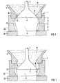
- the shut-off device 1 comprises a on a drive rod 2 arranged locking piece 4. Die Drive rod 2 is arranged inside a container 6, in which there is powdered medium M.
- the Closure piece 4 is slidably disposed in a drain channel 8.
- the drain channel 8 comprises a first, in longitudinal section round area 10 and an underlying second, conical region 12.
- the first region 10, d. H. the entry or acceleration area, and the second area 12, d. H. the exit or metering area, are arranged to each other in such a way that the drain channel 8 is approximately heart-shaped in longitudinal section.
- the closure piece 4 is rounded at its closure edge 14 and conical in the area of its back surface 16 educated.
- the back surface 16 of the closure piece 4 and the inner surface of the first region 10 of the drain channel 4 are parallel to each other in longitudinal section.
- the docking area 18 has a smaller one Cross section on as the maximum cross section of the closure piece 4.
- the drive rod 2 is designed such that they are the weight of the closure piece 4, the container 6 and the medium M located in it. On in this way, the container 6 is sealed, and a unintentional opening of the container 6 is avoided.
- the drain channel 8 comprising the areas 10 and 12 is part the shut-off element 22 of a ball valve 24.
- the ball valve 24 is fixed to a docking ring 20 one - not shown - Mounted container to be filled, so that the filled Container can be sealed tightly and securely by means of the ball valve 24 is.
- the ball valve 24 can also be firmly connected to the container 6, so that a tight Closing the container 6 is guaranteed.
- the container 6 is opened the ball valve 24 arranged on the container to be filled in such a way placed that the closure piece 4 in the drain channel 8th is slidable into it.
- the shut-off device is open 1 is the closure piece 4 in the drain channel 8 moved in ( Figure 2).
Landscapes
- Engineering & Computer Science (AREA)
- Mechanical Engineering (AREA)
- General Engineering & Computer Science (AREA)
- Physics & Mathematics (AREA)
- Fluid Mechanics (AREA)
- Feeding, Discharge, Calcimining, Fusing, And Gas-Generation Devices (AREA)
- Containers And Packaging Bodies Having A Special Means To Remove Contents (AREA)
Description
Claims (6)
- Absperreinrichtung für einen Behälter für ein pulverförmiges Medium mit einem in einem Ablaufkanal verschiebbar angeordneten Verschlußstück, wobei der Ablaufkanal (8) einen ersten, im Längsschnitt runden Bereich (10) umfaßt,
dadurch gekennzeichnet, daß der Ablaufkanal (8) einen unter dem ersten Bereich (10) liegenden zweiten, konisch ausgebildeten Bereich (12) umfaßt. - Absperreinrichtung nach Anspruch 1,
dadurch gekennzeichnet, daß das Verschlußstück (4) an seiner Verschlußkante (14) abgerundet ist. - Absperreinrichtung nach Anspruch 1 oder 2,
dadurch gekennzeichnet, daß der Ablaufkanal (8) Teil des Absperrorgans (22) eines Kugelhahns (24) ist. - Absperreinrichtung nach einem der Ansprüche 1 bis 3,
dadurch gekennzeichnet, daß das Verschlußstück (4) eine koaxial zum Ablaufkanal (8) angeordnete, innerhalb des Behälters (6) verlaufende Antriebsstange (2) aufweist. - Absperreinrichtung nach einem der Ansprüche 1 bis 4,
dadurch gekennzeichnet, daß das Verschlußstück (4) kegelförmig ausgebildet ist. - Absperreinrichtung nach einem der Ansprüche 1 bis 5,
dadurch gekennzeichnet, daß das Verschlußstück (4) eine zur Innenfläche des ersten Bereichs (10) des Ablaufkanals (8) im Längsschnitt parallel verlaufende Rückenfläche (16) aufweist.
Applications Claiming Priority (2)
| Application Number | Priority Date | Filing Date | Title |
|---|---|---|---|
| DE19522360A DE19522360C1 (de) | 1995-06-20 | 1995-06-20 | Absperreinrichtung für einen Behälter für ein pulverförmiges Medium |
| DE19522360 | 1995-06-20 |
Publications (2)
| Publication Number | Publication Date |
|---|---|
| EP0750143A1 EP0750143A1 (de) | 1996-12-27 |
| EP0750143B1 true EP0750143B1 (de) | 1999-03-24 |
Family
ID=7764783
Family Applications (1)
| Application Number | Title | Priority Date | Filing Date |
|---|---|---|---|
| EP96109433A Expired - Lifetime EP0750143B1 (de) | 1995-06-20 | 1996-06-12 | Absperreinrichtung für einen Behälter für ein pulverförmiges Medium |
Country Status (2)
| Country | Link |
|---|---|
| EP (1) | EP0750143B1 (de) |
| DE (2) | DE19522360C1 (de) |
Families Citing this family (3)
| Publication number | Priority date | Publication date | Assignee | Title |
|---|---|---|---|---|
| US9004094B2 (en) | 2006-02-23 | 2015-04-14 | Tetra Laval Holdings & Finance S.A. | Powder valve |
| DE102013100860A1 (de) * | 2013-01-29 | 2014-07-31 | Miele & Cie. Kg | Dosiereinrichtung für schüttfähiges Gut |
| CN115489893B (zh) * | 2022-09-16 | 2023-06-16 | 南华大学 | 放射性粉末物料储料罐及其拆盖装盖方法 |
Family Cites Families (4)
| Publication number | Priority date | Publication date | Assignee | Title |
|---|---|---|---|---|
| GB203876A (en) * | 1922-08-19 | 1923-09-20 | James Talbot Reeve | Improvements in appliances for delivering substances in powder form |
| DE700720C (de) * | 1939-03-14 | 1940-12-27 | Bahnbedarf Akt Ges Vorm Orenst | Fuehrung fuer die Haltestange des Bodenkegelverschlusses bei Kuebeln |
| US2267057A (en) * | 1940-11-20 | 1941-12-23 | Verner Jules | Valve |
| CH516758A (de) * | 1971-01-18 | 1971-12-15 | Rickenbach Hugo | Schnellschlussventil |
-
1995
- 1995-06-20 DE DE19522360A patent/DE19522360C1/de not_active Expired - Fee Related
-
1996
- 1996-06-12 DE DE59601481T patent/DE59601481D1/de not_active Expired - Lifetime
- 1996-06-12 EP EP96109433A patent/EP0750143B1/de not_active Expired - Lifetime
Also Published As
| Publication number | Publication date |
|---|---|
| EP0750143A1 (de) | 1996-12-27 |
| DE19522360C1 (de) | 1996-08-14 |
| DE59601481D1 (de) | 1999-04-29 |
Similar Documents
| Publication | Publication Date | Title |
|---|---|---|
| DE1752543A1 (de) | Vorrichtung zum Putzen und zur Oberflaechenbearbeitung von Metall | |
| DE3704901A1 (de) | Fuellventil | |
| DE19522360C1 (de) | Absperreinrichtung für einen Behälter für ein pulverförmiges Medium | |
| DE3717239C1 (de) | Absperrventil | |
| DE60126064T2 (de) | Verfahren und vorrichtung zum verpacken von ultrafeinem pulver in behälter | |
| CH661577A5 (de) | Sanitaerarmatur. | |
| EP0196425A2 (de) | Dosierschieber für feinkörnige Feststoffe | |
| EP0522284B1 (de) | Feuerfeste Verschlussplatte für einen Schiebeverschluss am Ausguss eines Metallschmelze enthaltenden Gefässes | |
| EP0058829B1 (de) | Tropfkammer in einem Ableitungssystem für Körpersekret, insbesondere Urin | |
| EP3137396B1 (de) | Verschlussanordnung, verfahren zum verschliessen eines verschlusses und schüttgutbehälter damit | |
| EP0655611B1 (de) | Behälter zur Aufnahme von Schüttgut mit einem Doppelkegelverschluss | |
| DE2833628A1 (de) | Rueckladegeraet fuer schuettguthalden | |
| DE3436357C2 (de) | Förderkanal für pulver- oder kornförmige Materialien | |
| DE60219154T2 (de) | Vorrichtung und verfahren zur entfernung eines schmutzstoffs aus einem diesen enthaltenden fluid | |
| EP0615083B1 (de) | Sicherheitsschliessvorrichtung für Behälteröffnungen | |
| DE102011001276A1 (de) | Entlüftungsvorrichtung | |
| EP2328700B1 (de) | Schiebeverschluss für metallurgische gefässe sowie dazugehörige ausgusshülse | |
| DE4443307C1 (de) | Partikeldosiervorrichtung | |
| DE102010037145B3 (de) | Dosiereinrichtung | |
| DE3143795A1 (de) | "ventil zur stroemungsmittelzufuhr" | |
| DE102017000741B4 (de) | Dosiervorrichtung und Dosierverfahren | |
| DE68497C (de) | Selbstthätig schliefsendes Schlauch ventil | |
| DE29922397U1 (de) | Müllcontainereinrichtung | |
| DE4038816A1 (de) | Vorrichtung zum zufuehren eines zugabemittels in fluessigkeitsbehaelter, insbesondere in spuelwassersysteme | |
| DE2425508C3 (de) | Aufgabebunker |
Legal Events
| Date | Code | Title | Description |
|---|---|---|---|
| PUAI | Public reference made under article 153(3) epc to a published international application that has entered the european phase |
Free format text: ORIGINAL CODE: 0009012 |
|
| AK | Designated contracting states |
Kind code of ref document: A1 Designated state(s): DE FR GB |
|
| 17P | Request for examination filed |
Effective date: 19970130 |
|
| R17P | Request for examination filed (corrected) |
Effective date: 19970121 |
|
| GRAG | Despatch of communication of intention to grant |
Free format text: ORIGINAL CODE: EPIDOS AGRA |
|
| GRAG | Despatch of communication of intention to grant |
Free format text: ORIGINAL CODE: EPIDOS AGRA |
|
| GRAH | Despatch of communication of intention to grant a patent |
Free format text: ORIGINAL CODE: EPIDOS IGRA |
|
| 17Q | First examination report despatched |
Effective date: 19980902 |
|
| GRAH | Despatch of communication of intention to grant a patent |
Free format text: ORIGINAL CODE: EPIDOS IGRA |
|
| GRAA | (expected) grant |
Free format text: ORIGINAL CODE: 0009210 |
|
| AK | Designated contracting states |
Kind code of ref document: B1 Designated state(s): DE FR GB |
|
| REF | Corresponds to: |
Ref document number: 59601481 Country of ref document: DE Date of ref document: 19990429 |
|
| ET | Fr: translation filed | ||
| GBT | Gb: translation of ep patent filed (gb section 77(6)(a)/1977) |
Effective date: 19990510 |
|
| PLBE | No opposition filed within time limit |
Free format text: ORIGINAL CODE: 0009261 |
|
| STAA | Information on the status of an ep patent application or granted ep patent |
Free format text: STATUS: NO OPPOSITION FILED WITHIN TIME LIMIT |
|
| 26N | No opposition filed | ||
| REG | Reference to a national code |
Ref country code: GB Ref legal event code: IF02 |
|
| REG | Reference to a national code |
Ref country code: GB Ref legal event code: 732E |
|
| REG | Reference to a national code |
Ref country code: FR Ref legal event code: TP |
|
| REG | Reference to a national code |
Ref country code: FR Ref legal event code: CD |
|
| REG | Reference to a national code |
Ref country code: FR Ref legal event code: CA |
|
| REG | Reference to a national code |
Ref country code: DE Ref legal event code: R082 Ref document number: 59601481 Country of ref document: DE Representative=s name: MOERTEL, ALFRED, DIPL.-PHYS. DR.RER.NAT., DE |
|
| REG | Reference to a national code |
Ref country code: DE Ref legal event code: R082 Ref document number: 59601481 Country of ref document: DE Representative=s name: MEISSNER BOLTE & PARTNER GBR, DE Effective date: 20131112 Ref country code: DE Ref legal event code: R082 Ref document number: 59601481 Country of ref document: DE Representative=s name: MOERTEL, ALFRED, DIPL.-PHYS. DR.RER.NAT., DE Effective date: 20131112 Ref country code: DE Ref legal event code: R081 Ref document number: 59601481 Country of ref document: DE Owner name: AREVA GMBH, DE Free format text: FORMER OWNER: AREVA NP GMBH, 91052 ERLANGEN, DE Effective date: 20131112 |
|
| REG | Reference to a national code |
Ref country code: DE Ref legal event code: R082 Ref document number: 59601481 Country of ref document: DE Representative=s name: MEISSNER BOLTE & PARTNER GBR, DE |
|
| PGFP | Annual fee paid to national office [announced via postgrant information from national office to epo] |
Ref country code: GB Payment date: 20140620 Year of fee payment: 19 |
|
| PGFP | Annual fee paid to national office [announced via postgrant information from national office to epo] |
Ref country code: DE Payment date: 20140625 Year of fee payment: 19 |
|
| PGFP | Annual fee paid to national office [announced via postgrant information from national office to epo] |
Ref country code: FR Payment date: 20140617 Year of fee payment: 19 |
|
| REG | Reference to a national code |
Ref country code: DE Ref legal event code: R119 Ref document number: 59601481 Country of ref document: DE |
|
| GBPC | Gb: european patent ceased through non-payment of renewal fee |
Effective date: 20150612 |
|
| REG | Reference to a national code |
Ref country code: FR Ref legal event code: ST Effective date: 20160229 |
|
| PG25 | Lapsed in a contracting state [announced via postgrant information from national office to epo] |
Ref country code: GB Free format text: LAPSE BECAUSE OF NON-PAYMENT OF DUE FEES Effective date: 20150612 Ref country code: DE Free format text: LAPSE BECAUSE OF NON-PAYMENT OF DUE FEES Effective date: 20160101 |
|
| PG25 | Lapsed in a contracting state [announced via postgrant information from national office to epo] |
Ref country code: FR Free format text: LAPSE BECAUSE OF NON-PAYMENT OF DUE FEES Effective date: 20150630 |